chipKIT™ Uno32™ Jumper Settings
Revision: May 23, 2011
1300 NE Henley Court, Suite 3
Pullman, WA 99163
(509) 334 6306 Voice | (509) 334 6300 Fax
The chipKIT™ Development Platforms are based off the PIC32 Microcontroller. These are
32-bit products that bring unprecedented features to the Arduino™ community. In order to
maintain compatibility with existing hardware/software while maintaining user accessibility
to these advanced features, additional jumpers and row headers are provided. This
document describes the functionality of the jumpers listed in figure 1.
Figure 1: chipKIT™ UNO32 Jumpers
Jumper
Function
JP2
POWER SELECT: Used to connect/bypass on-board 5V regulator when
using a power supply connected to J4
J4 supply is regulated (i.e. 5V will be
present on 5V pin)
J4 supply bypasses regulator (i.e.
Supply voltage will be present on 5V
pin)
Note: A 3.3V on-board regulator will always be enable regardless of JP2 settings
to protect the PIC32 MCU
Not sure what this does? Play it safe and keep JP2 on the two right-most
pins. (i.e. J4 supply is regulated)
Doc: DSD-0000302
page 1 of 2
Copyright Digilent, Inc. All rights reserved. Other product and company names mentioned may be trademarks of their respective owners.
�chipKIT™ Uno32™ Jumper Settings
JP4
PWM/DIGITAL SELECT: Configures pin 10 on J5 to be used as a PWM
output or a Digital Input/Output.
Pin 10 configured as a Digital
Input/Output
JP5/JP7
Pin 10 configured as a PWM output
SPI SELECT: Used to configure the chipKIT™ as either a Master or Slave
when using the SPI (Serial Peripheral Interface). The chipKIT™ board can
be connected to another device or even another chipKIT™ through the SPI
connector (J8).
chipKIT™ configured as a SPI Master
chipKIT™ configured as a SPI Slave
For more information on SPI, please visit Wikipedia’s SPI page at:
http://en.wikipedia.org/wiki/Serial_Peripheral_Interface_Bus#Mode_Numbers
JP6/JP8
I2C/ANALOG PIN SELECT: Used to configure A4 and A5 for functionality as
an Analog input or to be used as I2C communication pins.
A4 and A5 on J7 are configured to
be used as analog inputs
A4 and A5 are configured to be used as
I2C communication lines (A4 – SDA, A5 –
SCL )
For more information on I2C, please visit Wikipedia’s I2C page at:
http://en.wikipedia.org/wiki/I2C
www.digilentinc.com
page 2 of 2
Copyright Digilent, Inc. All rights reserved. Other product and company names mentioned may be trademarks of their respective owners.
�
很抱歉,暂时无法提供与“TDGL002”相匹配的价格&库存,您可以联系我们找货
免费人工找货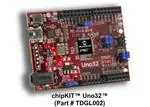


 工商网监
湘ICP备2023018690号
工商网监
湘ICP备2023018690号
