REVISIONS
LTR
A
DESCRIPTION
Add case outline L. - drw
DATE (YR-MO-DA)
APPROVED
99-09-01
Raymond Monnin
REV
SHEET
REV
SHEET
REV STATUS
OF SHEETS
PMIC N/A
STANDARD
MICROCIRCUIT
DRAWING
THIS DRAWING IS AVAILABLE
FOR USE BY ALL
DEPARTMENTS
AND AGENCIES OF THE
DEPARTMENT OF DEFENSE
AMSC N/A
REV
A
A
A
A
A
A
A
A
A
A
A
SHEET
1
2
3
4
5
6
7
8
9
10
11
PREPARED BY
Dan Wonnell
DEFENSE SUPPLY CENTER COLUMBUS
COLUMBUS, OHIO 43216
CHECKED BY
Ray Monnin
APPROVED BY
Ray Monnin
MICROCIRCUIT, DIGITAL-LINEAR, CMOS, SINGLE
SUPPLY, 600 KSPS, 12-BIT, A/D CONVERTER,
MONOLITHIC SILICON
DRAWING APPROVAL DATE
96-07-25
SIZE
REVISION LEVEL
A
SHEET
DSCC FORM 193
SEP 96
DISTRIBUTION STATEMENT A. Approved for public release; distribution is unlimited.
CAGE CODE
5962-96846
67268
1
OF
11
5962-E459-99
�1. SCOPE
1.1 Scope. This drawing documents two product assurance class levels consisting of high reliability (device classes Q and M)
and space application (device class V). A choice of case outlines and lead finishes are available and are reflected in the Part or
Identifying Number (PIN). When available, a choice of Radiation Hardness Assurance (RHA) levels are reflected in the PIN.
1.2 PIN. The PIN is as shown in the following example:
5962
-
96846
01
Q
L
A
*
*
*
*
*
*
*
*
*
*
*
*
*
*
*
*
*
*
Federal
stock class
designator
\
RHA
designator
(see 1.2.1)
Device
type
(see 1.2.2)
Device
class
designator
(see 1.2.3)
Case
outline
(see 1.2.4)
Lead
finish
(see 1.2.5)
/
\/
Drawing number
1.2.1 RHA designator. Device classes Q and V RHA marked devices meet the MIL-PRF-38535 specified RHA levels and are
marked with the appropriate RHA designator. Device class M RHA marked devices meet the MIL-PRF-38535, appendix A
specified RHA levels and are marked with the appropriate RHA designator. A dash (-) indicates a non-RHA device.
1.2.2 Device type(s). The device type(s) identify the circuit function as follows:
Device type
01
Generic number
Circuit function
7892S
Single supply 12-bit 600 KSPS ADC
1.2.3 Device class designator. The device class designator is a single letter identifying the product assurance level as follows:
Device class
M
Device requirements documentation
Vendor self-certification to the requirements for MIL-STD-883 compliant, non-JAN
class level B microcircuits in accordance with MIL-PRF-38535, appendix A
Q or V
Certification and qualification to MIL-PRF-38535
1.2.4 Case outline(s). The case outline(s) are as designated in MIL-STD-1835 and as follows:
Outline letter
J
L
Descriptive designator
GDIP1-T24 or CDIP2-T24
GDIP3-T24 or CDIP4-T24
Terminals
Package style
24
24
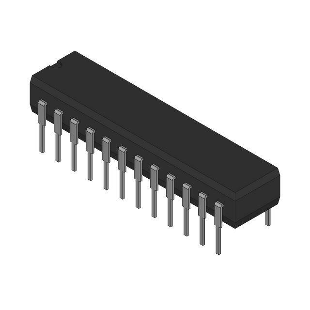
Dual-in-line
Dual-in-line
1.2.5 Lead finish. The lead finish is as specified in MIL-PRF-38535 for device classes Q and V or
MIL-PRF-38535, appendix A for device class M.
SIZE
STANDARD
MICROCIRCUIT DRAWING
DEFENSE SUPPLY CENTER COLUMBUS
COLUMBUS, OHIO 43216-5000
DESC FORM 193A
JUL 94
5962-96846
A
REVISION LEVEL
A
SHEET
2
�1.3 Absolute maximum ratings. 1/
VDD to AGND . . . . . . . . . . . . . . . . . . . . . . . . . . . . . . . . . . . . . .
VDD to DGND . . . . . . . . . . . . . . . . . . . . . . . . . . . . . . . . . . . . . .
Analog input voltage to AGND . . . . . . . . . . . . . . . . . . . . . . . .
Reference input voltage to AGND . . . . . . . . . . . . . . . . . . . . .
Digital input voltage to DGND . . . . . . . . . . . . . . . . . . . . . . . . .
Digital output voltage to DGND . . . . . . . . . . . . . . . . . . . . . . . .
Power dissipation (PD) . . . . . . . . . . . . . . . . . . . . . . . . . . . . . . .
Storage temperature range . . . . . . . . . . . . . . . . . . . . . . . . . . .
Junction temperature (TJ) . . . . . . . . . . . . . . . . . . . . . . . . . . . .
Lead temperature (soldering, 10 sec) . . . . . . . . . . . . . . . . . . .
Thermal resistance, junction-to-ambient (2JA) . . . . . . . . . . . .
-0.3 V dc to +7 V dc
-0.3 V dc to +7 V dc
±17 V dc
-0.3 V dc to VDD + 0.3 V dc
-0.3 V dc to VDD + 0.3 V dc
-0.3 V dc to VDD + 0.3 V dc
450 mW
-65EC to +150EC
+150EC
+300EC
70EC/W
1.4 Recommended operating conditions.
Ambient operating temperature range (TA) . . . . . . . . . . . . . . .
-55EC to +125EC
2. APPLICABLE DOCUMENTS
2.1 Government specification, standards, and handbooks. The following specification, standards, and handbooks form a part of
this drawing to the extent specified herein. Unless otherwise specified, the issues of these documents are those listed in the issue
of the Department of Defense Index of Specifications and Standards (DoDISS) and supplement thereto, cited in the solicitation.
SPECIFICATION
MILITARY
MIL-PRF-38535 - Integrated Circuits, Manufacturing, General Specification for.
STANDARDS
MILITARY
MIL-STD-883 MIL-STD-973 MIL-STD-1835 -
Test Methods and Procedures for Microelectronics.
Configuration Management.
Microcircuit Case Outlines.
HANDBOOKS
MILITARY
MIL-HDBK-103 MIL-HDBK-780 -
List of Standard Microcircuit Drawings (SMD's).
Standard Microcircuit Drawings.
(Unless otherwise indicated, copies of the specification, standards, and handbooks are available from the Standardization
Document Order Desk, 700 Robbins Avenue, Building 4D, Philadelphia, PA 19111-5094.)
2.2 Order of precedence. In the event of a conflict between the text of this drawing and the references cited herein, the text of
this drawing takes precedence. Nothing in this document, however, supersedes applicable laws and regulations unless a specific
exemption has been obtained.
1/
Stresses above the absolute maximum rating may cause permanent damage to the device. Extended operation at the
maximum levels may degrade performance and affect reliability.
SIZE
STANDARD
MICROCIRCUIT DRAWING
DEFENSE SUPPLY CENTER COLUMBUS
COLUMBUS, OHIO 43216-5000
DESC FORM 193A
JUL 94
5962-96846
A
REVISION LEVEL
A
SHEET
3
�3. REQUIREMENTS
3.1 Item requirements. The individual item requirements for device classes Q and V shall be in accordance with
MIL-PRF-38535 and as specified herein or as modified in the device manufacturer's Quality Management (QM) plan. The
modification in the QM plan shall not affect the form, fit, or function as described herein. The individual item requirements for device
class M shall be in accordance with MIL-PRF-38535, appendix A for non-JAN class level B devices and as specified herein.
3.2 Design, construction, and physical dimensions. The design, construction, and physical dimensions shall be as specified in
MIL-PRF-38535 and herein for device classes Q and V or MIL-PRF-38535, appendix A and herein for device class M.
3.2.1 Case outline. The case outline shall be in accordance with 1.2.4 herein.
3.2.2 Terminal connections. The terminal connections shall be as specified on figure 1.
3.3 Electrical performance characteristics and postirradiation parameter limits. Unless otherwise specified herein, the electrical
performance characteristics and postirradiation parameter limits are as specified in table I and shall apply over the full ambient
operating temperature range.
3.4 Electrical test requirements. The electrical test requirements shall be the subgroups specified in table II. The electrical tests
for each subgroup are defined in table I.
3.5 Marking. The part shall be marked with the PIN listed in 1.2 herein. In addition, the manufacturer's PIN may also be marked
as listed in MIL-HDBK-103. For packages where marking of the entire SMD PIN number is not feasible due to space limitations, the
manufacturer has the option of not marking the "5962-" on the device. For RHA product using this option, the RHA designator
shall still be marked. Marking for device classes Q and V shall be in accordance with MIL-PRF-38535. Marking for device class M
shall be in accordance with MIL-PRF-38535, appendix A.
3.5.1 Certification/compliance mark. The certification mark for device classes Q and V shall be a "QML" or "Q" as required in
MIL-PRF-38535. The compliance mark for device class M shall be a "C" as required in MIL-PRF-38535, appendix A.
3.6 Certificate of compliance. For device classes Q and V, a certificate of compliance shall be required from a QML-38535 listed
manufacturer in order to supply to the requirements of this drawing (see 6.6.1 herein). For device class M, a certificate of
compliance shall be required from a manufacturer in order to be listed as an approved source of supply in MIL-HDBK-103 (see
6.6.2 herein). The certificate of compliance submitted to DSCC-VA prior to listing as an approved source of supply for this drawing
shall affirm that the manufacturer's product meets, for device classes Q and V, the requirements of MIL-PRF-38535 and herein or
for device class M, the requirements of MIL-PRF-38535, appendix A and herein.
3.7 Certificate of conformance. A certificate of conformance as required for device classes Q and V in
MIL-PRF-38535 or for device class M in MIL-PRF-38535, appendix A shall be provided with each lot of microcircuits delivered to
this drawing.
3.8 Notification of change for device class M. For device class M, notification to DSCC-VA of change of product (see 6.2 herein)
involving devices acquired to this drawing is required for any change as defined in MIL-STD-973.
3.9 Verification and review for device class M. For device class M, DSCC, DSCC's agent, and the acquiring activity retain the
option to review the manufacturer's facility and applicable required documentation. Offshore documentation shall be made available
onshore at the option of the reviewer.
3.10 Microcircuit group assignment for device class M. Device class M devices covered by this drawing shall be in microcircuit
group number 81 (see MIL-PRF-38535, appendix A).
SIZE
STANDARD
MICROCIRCUIT DRAWING
DEFENSE SUPPLY CENTER COLUMBUS
COLUMBUS, OHIO 43216-5000
DESC FORM 193A
JUL 94
5962-96846
A
REVISION LEVEL
A
SHEET
4
�TABLE I. Electrical performance characteristics.
Test
Symbol
Conditions 1/
-55°C # TA # +125°C
unless otherwise specified
Group A
subgroups
Device
type
Limits
Min
Unit
Max
1, 2, 3
01
THD
1, 2, 3
01
-78
dB
Peak harmonic or spurious
distortion
PHD
1, 2, 3
01
-79
dB
Intermodulation distortion
IMD
1, 2, 3
01
-78
dB
Resolution
RES
1, 2, 3
01
12
Bits
Minimum resolution for
which no codes are
guaranteed
RESMIN
1, 2, 3
01
12
Bits
Relative accuracy
RA
1, 2, 3
01
±1
LSB
Differential nonlinearity
DNL
1, 2, 3
01
±1
LSB
Positive and negative fullscale error
FSE
1, 2, 3
01
±5
LSB
Bipolalr zero error
BZE
1, 2, 3
01
±3
LSB
Input voltage range
VIN
Input applied to VIN1 with
VIN2 grounded
1, 2, 3
01
±10
V
Input resistance
RIN
Input applied to VIN1 with
VIN2 grounded
1, 2, 3
01
REF IN input voltage range
VREFIN
See 4.4.1c
4
01
2.38
Input impedance
RREF
Resistor connected to
internal reference node
1, 2, 3
01
1.6
Reference input
capacitance
CRIN
See 4.4.1c
4
01
10
pF
REF OUT error
VRE
1
01
±10
mV
Signal to noise ratio +
distortion ratio
SNR
Total harmonic distortion
fIN = 100 kHz,
fSAMPLE = 500 ksps
fs = 49 kHz, fb = 50 kHz
70
dB
kS
8
2, 3
2.625
V
kS
±25
Input high voltage
VINH
VDD = 5 V ±5%
1, 2, 3
01
2.4
V
Input low voltage
VINL
VDD = 5 V ±5%
1, 2, 3
01
0.8
V
Input current
IIN
VIN = 0 V to VDD
1, 2, 3
01
±10
µA
Input capacitance
CIN
See 4.4.1c
4
01
10
pF
Output high voltage
VOH
ISOURCE = 200 µA
1, 2, 3
01
Output low voltage
VOL
ISINK = 1.6 mA
1, 2, 3
01
4
V
0.4
V
See footnotes at end of table.
SIZE
STANDARD
MICROCIRCUIT DRAWING
DEFENSE SUPPLY CENTER COLUMBUS
COLUMBUS, OHIO 43216-5000
DESC FORM 193A
JUL 94
5962-96846
A
REVISION LEVEL
A
SHEET
5
�TABLE I. Electrical performance characteristics - continued.
Test
Symbol
Conditions 1/
-55°C # TA # +125°C
unless otherwise specified
Floating state capacitance
CFS
DB11 - DB0, see 4.4.1c
Floating state leakage
current
ILKG
DB11 - DB0
Power supply current
IDD
Power dissipation
Group A
subgroups
Device
type
Limits
Min
Max
01
15
pF
1, 2, 3
01
±10
µA
normal operation
1, 2, 3
01
19
mA
PD
normal operation
1, 2, 3
01
95
mW
Conversion time
tCONV
2/, see figure 2
1, 2, 3
01
1.68
µs
Acquisition time
tACQ
2/, see figure 2, see 4.4.1c
9, 10, 11
01
320
ns
t1
2/, see figure 2, see 4.4.1c
9, 10, 11
01
45
ns
t2
2/, see figure 2, see 4.4.1c
9, 10, 11
01
60
ns
t3
2/, see figure 2, see 4.4.1c
9, 10, 11
01
0
ns
C&
&
S to &
R&
D setup time
t4
2/, see figure 2, see 4.4.1c
9, 10, 11
01
0
ns
Read pulse width
t5
2/, see figure 2, see 4.4.1c
9, 10, 11
01
45
ns
Data access time after falling
edge of &
R&
D
t6
2/, 3/, see figure 2,
see 4.4.1c
9, 10, 11
01
Bus relinquish time after
rising edge of &
R&
D
t7
2/, 4/, see figure 2,
see 4.4.1c
9, 10, 11
01
5
t8
2/, see figure 2, see 4.4.1c
9, 10, 11
01
0
ns
t9
2/, see figure 2, see 4.4.1c
9, 10, 11
01
200
ns
t10
2/, see figure 2, see 4.4.1c
9, 10, 11
01
35
ns
R&
&
F&
S low to data valid delay
t11
2/, 3/, see figure 2,
see 4.4.1c
9, 10 11
01
SCLK high pulse width
t12
2/, see figure 2, see 4.4.1c
9, 10, 11
01
25
ns
SCLK low pulse width
t13
2/, see figure 2, see 4.4.1c
9, 10, 11
01
25
ns
SCLK rising edge to data
valid hold time
t14
2/, 3/, see figure 2,
see 4.4.1c
9, 10, 11
01
5
ns
SCLK rising edge to data
valid delay time
t15
2/, 3/, see figure 2,
see 4.4.1c
9, 10, 11
01
t16
2/, see figure 2, see 4.4.1c
9, 10, 11
01
C&
&
O&
N&
V&
S&
T pulse width
E&
&
O&
C pulse width
E&
&
O&
C falling edge to &
C&
S
falling edge setup time
C&
&
S to &
R&
D hold time
R&
&
D to &
C&
O&
N&
V&
S&
T setup time
&&
R
F&
S low to SCLK falling
edge setup time
&&
R
F&
S to SCLK falling edge
hold time
4
Unit
40
ns
40
ns
30
ns
30
ns
30
ns
See footnotes at end of table.
SIZE
STANDARD
MICROCIRCUIT DRAWING
DEFENSE SUPPLY CENTER COLUMBUS
COLUMBUS, OHIO 43216-5000
DESC FORM 193A
JUL 94
5962-96846
A
REVISION LEVEL
A
SHEET
6
�TABLE I. Electrical performance characteristics - continued.
Test
Symbol
Conditions 1/
-55°C # TA # +125°C
unless otherwise specified
Group A
subgroups
Device
type
Limits
Unit
Min
Max
Bus relinquish time after
rising edge of &
R&
F&
S
t17
2/, 4/, see figure 2,
see 4.4.1c
9, 10, 11
01
0
30
ns
Bus relinquish time after
rising edge of SCLK
t17A
2/, 4/, see figure 2,
see 4.4.1c
9, 10, 11
01
0
30
ns
1/ VDD = +5 V ± 5%, AGND = DGND = 0 V, REF IN = +2.5 V.
2/ All input signals are measured with tr = tf = 1 ns (10% to 90% of +5 V) and timed from a voltage level of +1.6 V.
3/ Defined as the time required for an output to cross 0.8 V or 2.4 V.
4/ These times are derived from the measured time taken by the data outputs to change 0.5 V. The measured number is then
extrapulated back to remove the effects of charging or discharching the 50 pF capacitor. Therefore these timing characteristics are
the true bus relinquish times and as such are independent of external bus loading capacitances.
Device type
01
Case outline
J, L
Teminal number
Terminal symbol
1
2
3
4
5
6
7
8
9
10
11
12
13
14
15
16
17
18
19
20
21
22
23
24
VDD
S&
&
T&
A&
N&
D&
B&
Y
VIN2
VIN1
REF OUT/REF IN
AGND
MODE
DB11/LOW
DB10/LOW
DB9
DB8
DB7
DB6
DGND
DB5/SDATA
DB4/CSCLK
DB3/RFS
DB2
DB1
DB0(LSB)
R&
&
D
C&
&
S
E&
&
O&
C
C&
&
O&
N&
V&
S&
T
FIGURE 1. Terminal connections.
SIZE
STANDARD
MICROCIRCUIT DRAWING
DEFENSE SUPPLY CENTER COLUMBUS
COLUMBUS, OHIO 43216-5000
DESC FORM 193A
JUL 94
5962-96846
A
REVISION LEVEL
A
SHEET
7
�FIGURE 2. Timing waveforms.
SIZE
STANDARD
MICROCIRCUIT DRAWING
DEFENSE SUPPLY CENTER COLUMBUS
COLUMBUS, OHIO 43216-5000
DESC FORM 193A
JUL 94
5962-96846
A
REVISION LEVEL
A
SHEET
8
�4. QUALITY ASSURANCE PROVISIONS
4.1 Sampling and inspection. For device classes Q and V, sampling and inspection procedures shall be in accordance with MILPRF-38535 or as modified in the device manufacturer's Quality Management (QM) plan. The modification in the QM plan shall not
affect the form, fit, or function as described herein. For device class M, sampling and inspection procedures shall be in accordance
with MIL-PRF-38535, appendix A.
4.2 Screening. For device classes Q and V, screening shall be in accordance with MIL-PRF-38535, and shall be conducted on
all devices prior to qualification and technology conformance inspection. For device class M, screening shall be in accordance with
method 5004 of MIL-STD-883, and shall be conducted on all devices prior to quality conformance inspection.
4.2.1 Additional criteria for device class M.
a.
Burn-in test, method 1015 of MIL-STD-883.
(1) Test condition A, B, C, or D. The test circuit shall be maintained by the manufacturer under document revision level
control and shall be made available to the preparing or acquiring activity upon request. The test circuit shall specify
the inputs, outputs, biases, and power dissipation, as applicable, in accordance with the intent specified in test
method 1015.
(2) TA = +125EC, minimum.
b.
Interim and final electrical test parameters shall be as specified in table II herein.
4.2.2 Additional criteria for device classes Q and V.
a.
The burn-in test duration, test condition and test temperature, or approved alternatives shall be as specified in the device
manufacturer's QM plan in accordance with MIL-PRF-38535. The burn-in test circuit shall be maintained under document
revision level control of the device manufacturer's Technology Review Board (TRB) in accordance with MIL-PRF-38535
and shall be made available to the acquiring or preparing activity upon request. The test circuit shall specify the inputs,
outputs, biases, and power dissipation, as applicable, in accordance with the intent specified in test method 1015 of MILSTD-883.
b.
Interim and final electrical test parameters shall be as specified in table II herein.
c.
Additional screening for device class V beyond the requirements of device class Q shall be as specified in MIL-PRF38535, appendix B.
4.3 Qualification inspection for device classes Q and V. Qualification inspection for device classes Q and V shall be in
accordance with MIL-PRF-38535. Inspections to be performed shall be those specified in MIL-PRF-38535 and herein for groups
A, B, C, D, and E inspections (see 4.4.1 through 4.4.4).
4.4 Conformance inspection. Technology conformance inspection for classes Q and V shall be in accordance with MIL-PRF38535 including groups A, B, C, D, and E inspections and as specified herein except where option 2 of
MIL-PRF-38535 permits alternate in-line control testing. Quality conformance inspection for device class M shall be in accordance
with MIL-PRF-38535, appendix A and as specified herein. Inspections to be performed for device class M shall be those specified
in method 5005 of MIL-STD-883 and herein for groups A, B, C, D, and E inspections (see 4.4.1 through 4.4.4).
4.4.1 Group A inspection.
a.
Tests shall be as specified in table II herein.
b.
Subgroups 5, 6, 7, and 8 in table I, method 5005 of MIL-STD-883 shall be omitted.
c.
Subgroups 4, 9, 10, and 11 shall be measured only for the initial test and after process or design changes that may effect
these parameters and shall be guranteed to the limits specified in table I.
4.4.2 Group C inspection. The group C inspection end-point electrical parameters shall be as specified in table II herein.
SIZE
STANDARD
MICROCIRCUIT DRAWING
DEFENSE SUPPLY CENTER COLUMBUS
COLUMBUS, OHIO 43216-5000
DESC FORM 193A
JUL 94
5962-96846
A
REVISION LEVEL
A
SHEET
9
�TABLE II. Electrical test requirements.
Test requirements
Subgroups
(in accordance with
MIL-STD-883,
method 5005, table I)
Subgroups
(in accordance with
MIL-PRF-38535, table III)
Device
class M
Device
class Q
Device
class V
Interim electrical
parameters (see 4.2)
1, 2, 3
1, 2, 3
1, 2, 3
Final electrical
parameters (see 4.2)
1/ 1, 2, 3, 4,
9, 10, 11
1/ 1, 2, 3, 4,
9, 10, 11
1/ 1, 2, 3, 4,
1, 10, 11
1, 2, 3, 4,
9, 10, 11
1, 2, 3, 4,
9, 10, 11
1, 2, 3, 4,
9, 10, 11
Group A test
requirements (see 4.4)
Group C end-point electrical
parameters (see 4.4)
1
1
1
Group D end-point electrical
parameters (see 4.4)
1
1
1
Group E end-point electrical
parameters (see 4.4)
---
---
---
1/ PDA applies to subgroup 1.
4.4.2.1 Additional criteria for device class M. Steady-state life test conditions, method 1005 of MIL-STD-883:
a.
Test condition A, B, C or D. The test circuit shall be maintained by the manufacturer under document revision level control
and shall be made available to the preparing or acquiring activity upon request. The test circuit shall specify the inputs,
outputs, biases, and power dissipation, as applicable, in accordance with the intent specified in test method 1005 of MILSTD-883.
b.
TA = +125EC, minimum.
c.
Test duration: 1,000 hours, except as permitted by method 1005 of MIL-STD-883.
4.4.2.2 Additional criteria for device classes Q and V. The steady-state life test duration, test condition and test temperature, or
approved alternatives shall be as specified in the device manufacturer's QM plan in accordance with MIL-PRF-38535. The test
circuit shall be maintained under document revision level control by the device manufacturer's TRB in accordance with MIL-PRF38535 and shall be made available to the acquiring or preparing activity upon request. The test circuit shall specify the inputs,
outputs, biases, and power dissipation, as applicable, in accordance with the intent specified in test method 1005 of MIL-STD-883.
4.4.3 Group D inspection. The group D inspection end-point electrical parameters shall be as specified in table II herein.
4.4.4 Group E inspection. Group E inspection is required only for parts intended to be marked as radiation hardness assured
(see 3.5 herein).
a.
End-point electrical parameters shall be as specified in table II herein.
b.
For device classes Q and V, the devices or test vehicle shall be subjected to radiation hardness assured tests as specified
in MIL-PRF-38535 for the RHA level being tested. For device class M, the devices shall be subjected to radiation hardness
assured tests as specified in MIL-PRF-38535, appendix A for the RHA level being tested. All device classes must meet the
postirradiation end-point electrical parameter limits as defined in table I at TA = +25EC ±5EC, after exposure, to the
subgroups specified in table II herein.
c.
When specified in the purchase order or contract, a copy of the RHA delta limits shall be supplied.
SIZE
STANDARD
MICROCIRCUIT DRAWING
DEFENSE SUPPLY CENTER COLUMBUS
COLUMBUS, OHIO 43216-5000
DESC FORM 193A
JUL 94
5962-96846
A
REVISION LEVEL
A
SHEET
10
�5. PACKAGING
5.1 Packaging requirements. The requirements for packaging shall be in accordance with MIL-PRF-38535 for device classes Q
and V or MIL-PRF-38535, appendix A for device class M.
6. NOTES
6.1 Intended use. Microcircuits conforming to this drawing are intended for use for Government microcircuit applications (original
equipment), design applications, and logistics purposes.
6.1.1 Replaceability. Microcircuits covered by this drawing will replace the same generic device covered by a
contractor-prepared specification or drawing.
6.1.2 Substitutability. Device class Q devices will replace device class M devices.
6.2 Configuration control of SMD's. All proposed changes to existing SMD's will be coordinated with the users of record for the
individual documents. This coordination will be accomplished in accordance with MIL-STD-973 using DD Form 1692, Engineering
Change Proposal.
6.3 Record of users. Military and industrial users should inform Defense Supply Center Columbus when a system application
requires configuration control and which SMD's are applicable to that system. DSCC will maintain a record of users and this list will
be used for coordination and distribution of changes to the drawings. Users of drawings covering microelectronic devices (FSC
5962) should contact DSCC-VA, telephone (614) 692-0525.
6.4 Comments. Comments on this drawing should be directed to DSCC-VA, Columbus, Ohio 43216-5000, or telephone
(614) 692-0674.
6.5 Abbreviations, symbols, and definitions. The abbreviations, symbols, and definitions used herein are defined in MIL-PRF38535 and MIL-HDBK-1331.
6.6 Sources of supply.
6.6.1 Sources of supply for device classes Q and V. Sources of supply for device classes Q and V are listed in QML-38535.
The vendors listed in QML-38535 have submitted a certificate of compliance (see 3.6 herein) to DSCC-VA and have agreed to this
drawing.
6.6.2 Approved sources of supply for device class M. Approved sources of supply for class M are listed in MIL-HDBK-103. The
vendors listed in MIL-HDBK-103 have agreed to this drawing and a certificate of compliance (see 3.6 herein) has been submitted to
and accepted by DSCC-VA.
SIZE
STANDARD
MICROCIRCUIT DRAWING
DEFENSE SUPPLY CENTER COLUMBUS
COLUMBUS, OHIO 43216-5000
DESC FORM 193A
JUL 94
5962-96846
A
REVISION LEVEL
A
SHEET
11
�STANDARD MICROCIRCUIT DRAWING BULLETIN
DATE: 99-09-01
Approved sources of supply for SMD 5962-96846 are listed below for immediate acquisition information only and shall
be added to MIL-HDBK-103 and QML-38535 during the next revision. MIL-HDBK-103 and QML-38535 will be revised
to include the addition or deletion of sources. The vendors listed below have agreed to this drawing and a certificate of
compliance has been submitted to and accepted by DSCC-VA. This bulletin is superseded by the next dated revision of
MIL-HDBK-103 and QML-38535.
Standard
microcircuit drawing
PIN 1/
Vendor
CAGE
number
Vendor
similar
PIN 2/
5962-9684601QJA
3/
AD7892SQ-1/QML
5962-9684601QLA
24355
AD7892SQ-1/QML
1/ The lead finish shown for each PIN representing
a hermetic package is the most readily available
from the manufacturer listed for that part. If the
desired lead finish is not listed contact the vendor
to determine its availability.
2/ Caution. Do not use this number for item
acquisition. Items acquired to this number may not
satisfy the performance requirements of this drawing.
3/ Not available from an approved source.
Vendor CAGE
number
24355
Vendor name
and address
Analog Devices
804 Woburn Street
Wilmington, MA 01887-3462
The information contained herein is disseminated for convenience only and the
Government assumes no liability whatsoever for any inaccuracies in the
information bulletin.
�