High Common-Mode Voltage,
Difference Amplifier
AD629
FUNCTIONAL BLOCK DIAGRAM
Improved replacement for: INA117P and INA117KU
±270 V common-mode voltage range
Input protection to
±500 V common mode
±500 V differential mode
Wide power supply range (±2.5 V to ±18 V)
±10 V output swing on ±12 V supply
1 mA maximum power supply current
REF(–) 1
–IN 2
+IN 3
–VS
4
380kΩ
21.1kΩ
380kΩ
380kΩ
20kΩ
AD629
8
NC
7
+VS
6
OUTPUT
5
REF(+)
00783-001
FEATURES
NC = NO CONNECT
Figure 1.
GENERAL DESCRIPTION
HIGH ACCURACY DC PERFORMANCE
3 ppm maximum gain nonlinearity (AD629B)
20 μV/°C maximum offset drift (AD629A)
10 μV/°C maximum offset drift (AD629B)
10 ppm/°C maximum gain drift
The AD629 is a difference amplifier with a very high input,
common-mode voltage range. It is a precision device that allows
the user to accurately measure differential signals in the
presence of high common-mode voltages up to ±270 V.
The AD629 can replace costly isolation amplifiers in
applications that do not require galvanic isolation. The device
operates over a ±270 V common-mode voltage range and has
inputs that are protected from common-mode or differential
mode transients up to ±500 V.
EXCELLENT AC SPECIFICATIONS
77 dB minimum CMRR @ 500 Hz (AD629A)
86 dB minimum CMRR @ 500 Hz (AD629B)
500 kHz bandwidth
The AD629 has low offset, low offset drift, low gain error drift,
low common-mode rejection drift, and excellent CMRR over a
wide frequency range.
APPLICATIONS
High voltage current sensing
Battery cell voltage monitors
Power supply current monitors
Motor controls
Isolation
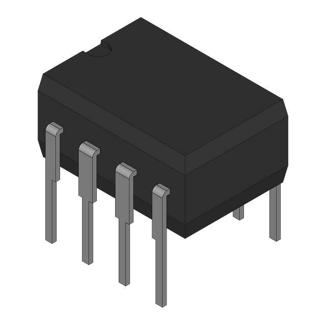
The AD629 is available in die and packaged form featuring
8-lead PDIP and 8-lead SOIC packages. For all packages
(including die) and grades, performance is guaranteed over
the industrial temperature range of −40°C to +85°C.
2mV/DIV
95
OUTPUT ERROR (2mV/DIV)
90
85
80
75
70
65
55
50
20
100
1k
FREQUENCY (Hz)
10k
20k
00783-003
60
00783-002
COMMON-MODE REJECTION RATIO (dB)
100
60V/DIV
–240
–120
0
120
COMMON-MODE VOLTAGE (V)
240
Figure 2. Common-Mode Rejection Ratio vs. Frequency
Figure 3. Error Voltage vs. Input Common-Mode Voltage
Information furnished by Analog Devices is believed to be accurate and reliable. However, no
responsibility is assumed by Analog Devices for its use, nor for any infringements of patents or other
rights of third parties that may result from its use. Specifications subject to change without notice. No
license is granted by implication or otherwise under any patent or patent rights of Analog Devices.
Trademarks and registered trademarks are the property of their respective owners.
One Technology Way, P.O. Box 9106, Norwood, MA 02062-9106, U.S.A.
Tel: 781.329.4700
www.analog.com
Fax: 781.461.3113 ©1999-2011 Analog Devices, Inc. All rights reserved.
Rev. C
�AD629
TABLE OF CONTENTS
Features .............................................................................................. 1
Basic Connections...................................................................... 11
Applications....................................................................................... 1
Single-Supply Operation ........................................................... 11
Functional Block Diagram .............................................................. 1
System-Level Decoupling and Grounding.............................. 11
General Description ......................................................................... 1
Using a Large Sense Resistor..................................................... 12
Revision History ............................................................................... 2
Output Filtering.......................................................................... 12
Specifications..................................................................................... 3
Output Current and Buffering.................................................. 13
Absolute Maximum Ratings............................................................ 4
A Gain of 19 Differential Amplifier......................................... 13
ESD Caution.................................................................................. 4
Error Budget Analysis Example 1 ............................................ 13
Pin Configuration and Function Descriptions............................. 5
Error Budget Analysis Example 2 ............................................ 14
Typical Performance Characteristics ............................................. 6
Outline Dimensions ....................................................................... 15
Theory of Operation ...................................................................... 10
Ordering Guide .......................................................................... 16
Applications..................................................................................... 11
REVISION HISTORY
4/11—Rev. B to Rev. C
Changes to General Description Section ...................................... 1
Added Endnote 1 in Table 1............................................................ 3
Added Figure 5; Renumbered Sequentially .................................. 4
Added Table 3; Renumbered Sequentially .................................... 4
Added Pin Configuration and Function Descriptions Section,
Figure 6, and Table 4 ........................................................................ 5
Changes to Ordering Guide .......................................................... 16
3/07—Rev. A to Rev. B
Updated Format and Layout .............................................Universal
Changes to Ordering Guide .......................................................... 15
3/00—Rev. 0 to Rev. A
10/99—Revision 0: Initial Version
Rev. C | Page 2 of 16
�AD629
SPECIFICATIONS
TA = 25°C, VS = ±15 V, unless otherwise noted.
Table 1.
Parameter
GAIN
Nominal Gain
Gain Error
Gain Nonlinearity
Gain vs. Temperature
OFFSET VOLTAGE
Offset Voltage
vs. Temperature
vs. Supply (PSRR)
INPUT
Common-Mode Rejection Ratio
Operating Voltage Range
Input Operating Impedance
OUTPUT
Operating Voltage Range
Output Short-Circuit Current
Capacitive Load
DYNAMIC RESPONSE
Small Signal –3 dB Bandwidth
Slew Rate
Full Power Bandwidth
Settling Time
OUTPUT NOISE VOLTAGE
0.01 Hz to 10 Hz
Spectral Density, ≥100 Hz 2
POWER SUPPLY
Operating Voltage Range
Quiescent Current
TEMPERATURE RANGE
For Specified Performance
1
2
Condition
VOUT = ±10 V, RL = 2 kΩ
Min
RL = 10 kΩ
TA = TMIN to TMAX
VS = ±5 V
TA = TMIN to TMAX
VS = ±5 V to ± 15 V
84
VCM = ±250 V dc
TA = TMIN to TMAX
VCM = 500 V p-p, dc to 500 Hz
VCM = 500 V p-p, dc to 1 kHz
Common mode
Differential
Common mode
Differential
77
73
77
RL = 10 kΩ
RL = 2 kΩ
VS = ±12 V, RL = 2 kΩ
±13
±12.5
±10
AD629A 1
Typ
Max
Min
1
0.01
4
1
3
10
1
0.01
4
1
3
0.2
1
0.1
6
100
20
0.05
10
90
88
86
82
86
88
96
±270
±13
±13
±12.5
±10
1000
500
2.1
28
15
12
5
1.7
±2.5
0.9
1.2
−40
±18
1
±2.5
+85
−40
Specifications for the AD629 A grade are also valid for the die model (listed in the Ordering Guide as AD629AC-WP).
See Figure 21.
Rev. C | Page 3 of 16
Unit
V/V
%
ppm
ppm
ppm/°C
mV
mV
μV/°C
dB
dB
dB
dB
dB
V
V
kΩ
kΩ
V
V
V
mA
pF
±25
15
550
VOUT = 0 V
TMIN to TMAX
0.5
1
10
200
800
1000
VOUT = 20 V p-p
0.01%, VOUT = 10 V step
0.1%, VOUT = 10 V step
0.01%, VCM = 10 V step, VDIFF = 0 V
0.03
10
3
10
90
200
800
1.7
TA = TMIN to TMAX
3
110
±270
±13
±25
Stable operation
AD629B
Typ
Max
500
2.1
28
15
12
5
kHz
V/μs
kHz
μs
μs
μs
15
550
μV p-p
nV/√Hz
0.9
1.2
±18
1
V
mA
mA
+85
°C
�AD629
ABSOLUTE MAXIMUM RATINGS
Table 2.
1a
1
Rating
±18 V
2
7
See Figure 4
See Figure 4
±300 V
±500 V
Indefinite
–VS − 0.3 V to +VS + 0.3 V
150°C
−55°C to +125°C
−65°C to +150°C
300°C
Y
3
4
6b
6a
5a
5b
X
Specification is for device in free air:
8-Lead PDIP, θJA = 100°C/W;
8-Lead SOIC, θJA = 155°C/W.
DIE SIZE: 1655µm (X) by 2465µm (Y)
Figure 5. Metallization Photograph
Stresses above those listed under Absolute Maximum Ratings
may cause permanent damage to the device. This is a stress
rating only; functional operation of the device at these or any
other conditions above those indicated in the operational
section of this specification is not implied. Exposure to absolute
maximum rating conditions for extended periods may affect
device reliability.
2.0
TJ = 150°C
8-LEAD PDIP
1.5
Table 3. Pin Pad Coordinates
Coordinates1
X
Y
−677
+1082
−534
+1084
Pad
1a
1b
Pin
REF(−)
2
3
4
5a
5b
−IN
+IN
−VS
REF(+)
−661
−661
+680
+396
+538
+939
−658
−800
−1084
−1084
6a
6b
OUTPUT
+681
+681
−950
−807
7
+VS
+680
+612
1.0
8-LEAD SOIC
0.5
0
–50 –40 –30 –20 –10 0 10 20 30 40 50 60
AMBIENT TEMPERATURE (°C)
00783-004
MAXIMUM POWER DISSIPATION (W)
1b
00783-041
Parameter
Supply Voltage, VS
Internal Power Dissipation1
8-Lead PDIP (N)
8-Lead SOIC (R)
Input Voltage Range, Continuous
Common-Mode and Differential, 10 sec
Output Short-Circuit Duration
Pin 1 and Pin 5
Maximum Junction Temperature
Operating Temperature Range
Storage Temperature Range
Lead Temperature (Soldering 60 sec)
70
80
90
1
Figure 4. Maximum Power Dissipation vs. Temperature for SOIC and PDIP
Description
For the die model, either
pad can be bonded because
1a and 1b are internally
shorted.
For the die model, either
pad can be bonded because
5a and 5b are internally
shorted.
For the die model, both
pads must be bonded
because 6a and 6b are not
internally shorted.
All coordinates are with respect to the center of the die.
ESD CAUTION
Rev. C | Page 4 of 16
�AD629
REF(–) 1
8
NC
–IN 2
AD629
7
+VS
+IN 3
TOP VIEW
(Not to Scale)
6
OUTPUT
5
REF(+)
–VS 4
NC = NO CONNECT
Figure 6. Pin Configuration
Table 4. Pin Function Descriptions
Pin No.
1
2
3
4
5
6
7
8
Mnemonic
REF(−)
−IN
+IN
−VS
REF(+)
OUTPUT
+VS
NC
Description
Negative Reference Voltage Input.
Inverting Input.
Noninverting Input.
Negative Supply Voltage.
Positive Reference Voltage Input.
Output.
Positive Supply Voltage.
No Connect. Do not connect to this pin.
Rev. C | Page 5 of 16
00783-040
PIN CONFIGURATION AND FUNCTION DESCRIPTIONS
�AD629
TYPICAL PERFORMANCE CHARACTERISTICS
100
400
90
360
80
320
COMMON-MODE VOLTAGE (±V)
60
50
40
30
10
0
100
1k
10k
100k
FREQUENCY (Hz)
1M
120
80
0
10M
2
4
6
8
10
12
14
16
POWER SUPPLY VOLTAGE (±V)
18
20
RL = 2kΩ
VS = ±18V
OUTPUT ERROR (2mV/DIV)
VS = ±15V
4V/DIV
VS = ±10V
–8
–4
0
4
VOUT (V)
8
12
16
VS = ±15V
VS = ±12V
00783-007
VS = ±12V
–12
0
Figure 10. Common-Mode Operating Range vs. Power Supply Voltage
VS = ±18V
OUTPUT ERROR (2mV/DIV)
160
RL = 10kΩ
2mV/DIV
–16
TA = –40°C
200
40
Figure 7. Common-Mode Rejection Ratio vs. Frequency
–20
TA = +85°C
240
00783-006
20
280
00783-009
70
TA = +25°C
VS = ±10V
–20
20
Figure 8. Typical Gain Error Normalized @ VOUT = 0 V and Output Voltage
Operating Range vs. Supply Voltage, RL = 10 kΩ (Curves Offset for Clarity)
–16
–12
–8
–4
4V/DIV
0
4
VOUT (V)
8
12
16
00783-010
COMMON-MODE REJECTION RATIO (dB)
TA = 25°C, VS = ±15 V, unless otherwise noted.
20
Figure 11. Typical Gain Error Normalized @ VOUT = 0 V and Output Voltage
Operating Range vs. Supply Voltage, RL = 2 kΩ (Curves Offset for Clarity)
RL = 1kΩ
VS = ±5V, RL = 10kΩ
OUTPUT ERROR (2mV/DIV)
VS = ±15V
VS = ±10V
–20
–16
–12
–8
–4
4V/DIV
0
4
VOUT (V)
8
12
16
VS = ±5V, RL = 1kΩ
00783-008
VS = ±12V
VS = ±5V, RL = 2kΩ
1V/DIV
VS = ±2.5V, RL = 1kΩ
–20
20
Figure 9. Typical Gain Error Normalized @ VOUT = 0 V and Output Voltage
Operating Range vs. Supply Voltage, RL = 1 kΩ (Curves Offset for Clarity)
–16
–12
–8
–4
0
4
VOUT (V)
8
12
16
00783-011
OUTPUT ERROR (2mV/DIV)
VS = ±18V
20
Figure 12. Typical Gain Error Normalized @ VOUT = 0 V and Output Voltage
Operating Range vs. Supply Voltage (Curves Offset for Clarity)
Rev. C | Page 6 of 16
�AD629
20µV/DIV
40µV/DIV
VS = ±15V
RL = 2kΩ
2.5V/DIV
–10
–5
0
VOUT (V)
5
00783-015
00783-012
ERROR (2ppm/DIV)
ERROR (0.8ppm/DIV)
VS = ±15V
RL = 10kΩ
2V/DIV
10
–10
Figure 13. Gain Nonlinearity; VS = ±15 V, RL = 10 kΩ
–8
–6
–4
–2
0
2
VOUT (V)
4
6
8
10
Figure 16. Gain Nonlinearity; VS = ±15 V, RL = 2kΩ
14.0
–40°C
VS = ±12V
RL = 10kΩ
13.0
–40°C
ERROR (1ppm/DIV)
OUTPUT VOLTAGE (V)
12.0
11.0
VS= ±15V
–10
–8
–6
–4
–2
0
2
VOUT (V)
4
6
8
9.0
–11.5
–12.0
–40°C
00783-013
–13.0
–13.5
10
+25°C
+85°C
0
2
4
6
8
10
12
14
OUTPUT CURRENT (mA)
16
11.5
VS = ±5V
RL = 1kΩ
–40°C
–40°C
OUTPUT VOLTAGE (V)
ERROR (6.67ppm/DIV)
9.5
8.5
VS= ±12V
+25°C
7.5
+85°C
6.5
–9.0
–9.5
–40°C
–1.8
–1.2
–0.6
0
0.6
VOUT (V)
1.2
1.8
2.4
Figure 15. Gain Nonlinearity; VS = ±5 V, RL = 1 kΩ
+25°C
–10.5
–11.0
3.0
00783-017
00783-014
0.6V/DIV
–2.4
20
+85°C
10.5
–10.0
–3.0
18
Figure 17. Output Voltage Operating Range vs. Output Current; VS = ±15 V
Figure 14. Gain Nonlinearity; VS = ±12 V, RL =10 kΩ
40µV/DIV
+25°C
10.0
–12.5
2V/DIV
+85°C
00783-016
20µV/DIV
+85°C
0
2
4
6
8
10
12
14
OUTPUT CURRENT (mA)
16
18
20
Figure 18. Output Voltage Operating Range vs. Output Current; VS = ±12 V
Rev. C | Page 7 of 16
�AD629
4.5
+85°C
–40°C
3.5
+85°C
1.5
0.5
VS= ±5V
+25°C
+85°C
–2.0
–2.5
–40°C
–3.0
–4.0
+85°C
+25°C
0
2
4
6
8
10
12
14
OUTPUT CURRENT (mA)
16
18
25mV/DIV
Figure 19. Output Voltage Operating Range vs. Output Current; VS = ±5 V
110
100
G = +1
RL = 2kΩ
CL = 1000pF
–VS
90
80
70
60
50
30
1.0
10
100
FREQUENCY (Hz)
1k
25mV/DIV
4µs/DIV
10k
Figure 20. Power Supply Rejection Ratio vs. Frequency
00783-022
40
0.1
Figure 23. Small Signal Pulse Response
5.0
4.5
G = +1
RL = 2kΩ
CL = 1000pF
4.0
3.5
3.0
2.5
2.0
1.5
1.0
00783-020
VOLTAGE NOISE SPECTRAL DENSITY (µV/ Hz)
Figure 22. Small Signal Pulse Response
+VS
00783-019
POWER SUPPLY REJECTION RATIO (dB)
120
4µs/DIV
20
00783-021
00783-018
+25°C
–3.5
0.5
0.01
0.1
1.0
10
100
FREQUENCY (Hz)
1k
10k
5V/DIV
5µs/DIV
100k
Figure 21. Voltage Noise Spectral Density vs. Frequency
Figure 24. Large Signal Pulse Response
Rev. C | Page 8 of 16
00783-023
OUTPUT VOLTAGE (V)
G = +1
RL = 2kΩ
CL = 1000pF
–40°C
2.5
�AD629
5V/DIV
5V/DIV
0V
+10V
VOUT
VOUT
–10V
OUTPUT
ERROR
OUTPUT
ERROR
1mV/DIV
10µs/DIV
00783-024
1mV = 0.01%
1mV/DIV
Figure 25. Settling Time to 0.01%, for 0 V to 10 V Output Step; G = −1, RL = 2 kΩ
300
200
150
100
150
100
0
150
–900
–600
–300
0
300
OFFSET VOLTAGE (µV)
600
900
Figure 29. Typical Distribution of Offset Voltage; Package Option N-8
400
400
N = 2180
n ≈ 200 PCS. FROM
10 ASSEMBLY LOTS
350
N = 2180
n ≈ 200 PCS. FROM
10 ASSEMBLY LOTS
300
250
200
150
250
200
150
100
50
50
00783-026
100
–400
–200
0
200
–1 GAIN ERROR (ppm)
400
0
–600
600
00783-029
NUMBER OF UNITS
300
0
–600
00783-028
00783-025
–100
–50
0
50
100
COMMON-MODE REJECTION RATIO (ppm)
Figure 26. Typical Distribution of Common-Mode Rejection; Package Option N-8
NUMBER OF UNITS
200
50
50
350
N = 2180
n ≈ 200 PCS. FROM
10 ASSEMBLY LOTS
250
NUMBER OF UNITS
NUMBER OF UNITS
N = 2180
n ≈ 200 PCS. FROM
10 ASSEMBLY LOTS
250
0
–150
10µs/DIV
Figure 28. Settling Time to 0.01% for 0 V to −10 V Output Step; G = −1, RL = 2kΩ
350
300
1mV = 0.01%
00783-027
0V
–400
–200
0
200
+1 GAIN ERROR (ppm)
400
600
Figure 30. Typical Distribution of +1 Gain Error; Package Option N-8
Figure 27. Typical Distribution of −1 Gain Error; Package Option N-8
Rev. C | Page 9 of 16
�AD629
THEORY OF OPERATION
To achieve high common-mode voltage range, an internal
resistor divider (Pin 3 or Pin 5) attenuates the noninverting
signal by a factor of 20. Other internal resistors (Pin 1, Pin 2,
and the feedback resistor) restore the gain to provide a differential
gain of unity. The complete transfer function equals
To reduce output drift, the op amp uses super beta transistors
in its input stage. The input offset current and its associated
temperature coefficient contribute no appreciable output
voltage offset or drift, which has the added benefit of reducing
voltage noise because the corner where 1/f noise becomes
dominant is below 5 Hz. To reduce the dependence of gain
accuracy on the op amp, the open-loop voltage gain of the op
amp exceeds 20 million, and the PSRR exceeds 140 dB.
REF(–) 1
VOUT = V (+IN) − V (−IN)
–IN 2
Laser wafer trimming provides resistor matching so that
common-mode signals are rejected while differential input
signals are amplified.
+IN 3
–VS 4
21.1kΩ
380kΩ
380kΩ
380kΩ
20kΩ
AD629
8
NC
7
+VS
6
OUTPUT
5
REF(+)
NC = NO CONNECT
Figure 31. Functional Block Diagram
Rev. C | Page 10 of 16
00783-001
The AD629 is a unity gain, differential-to-single-ended
amplifier (diff amp) that can reject extremely high commonmode signals (in excess of 270 V with 15 V supplies). It consists
of an operational amplifier (op amp) and a resistor network.
�AD629
APPLICATIONS
BASIC CONNECTIONS
REF (–)
1
+VS
REF (–)
1
–IN
RSHUNT
2
+IN
3
–VS
(SEE
TEXT)
AD629
380kΩ
380kΩ
+3V TO +18V
8
380kΩ
7
NC
+VS
6
20kΩ
4
5
0.1µF
(SEE
TEXT)
VOUT = ISHUNT × RSHUNT
REF (+)
0.1µF
NC = NO CONNECT
–VS
–3V TO –18V
00783-030
ISHUNT
21.1kΩ
–IN
ISHUNT
RSHUNT
2
+IN
3
AD629
380kΩ
380kΩ
VX
380kΩ
VY
–VS
+VS
8
7
NC
+VS
0.1µF
6
20kΩ
4
5
REF (+)
OUTPUT = VOUT – VREF
NC = NO CONNECT
VREF
00783-031
Figure 32 shows the basic connections for operating the AD629
with a dual supply. A supply voltage of between ±3 V and ±18 V
is applied between Pin 7 and Pin 4. Both supplies should be
decoupled close to the pins using 0.1 μF capacitors. Electrolytic
capacitors of 10 μF, also located close to the supply pins, may be
required if low frequency noise is present on the power supply.
While multiple amplifiers can be decoupled by a single set of
10 μF capacitors, each in amp should have its own set of 0.1 μF
capacitors so that the decoupling point can be located right at
the IC’s power pins.
21.1kΩ
Figure 33. Operation with a Single Supply
Applying a reference voltage to REF(+) and REF(–) and
operating on a single supply reduces the input common-mode
range of the AD629. The new input common-mode range
depends upon the voltage at the inverting and noninverting
inputs of the internal operational amplifier, labeled VX and VY
in Figure 33. These nodes can swing to within 1 V of either rail.
Therefore, for a (single) supply voltage of 10 V, VX and VY can
range between 1 V and 9 V. If VREF is set to 5 V, the permissible
common-mode range is +85 V to –75 V. The common-mode
voltage ranges can be calculated by
Figure 32. Basic Connections
VCM (±) = 20 VX/VY(±) − 19 VREF
The differential input signal, which typically results from a load
current flowing through a small shunt resistor, is applied to
Pin 2 and Pin 3 with the polarity shown to obtain a positive
gain. The common-mode range on the differential input signal
can range from −270 V to +270 V, and the maximum differential
range is ±13 V. When configured as shown in Figure 32, the
device operates as a simple gain-of-1, differential-to-singleended amplifier; the output voltage being the shunt resistance
times the shunt current. The output is measured with respect to
Pin 1 and Pin 5.
Pin 1 and Pin 5 (REF(–) and REF(+)) should be grounded for a
gain of unity and should be connected to the same low impedance
ground plane. Failure to do this results in degraded commonmode rejection. Pin 8 is a no connect pin and should be left open.
SINGLE-SUPPLY OPERATION
Figure 33 shows the connections for operating the AD629 with
a single supply. Because the output can swing to within only
about 2 V of either rail, it is necessary to apply an offset to the
output. This can be conveniently done by connecting REF(+)
and REF(–) to a low impedance reference voltage (some ADCs
provide this voltage as an output), which is capable of sinking
current. Therefore, for a single supply of 10 V, VREF may be set
to 5 V for a bipolar input signal. This allows the output to swing
±3 V around the central 5 V reference voltage. Alternatively, for
unipolar input signals, VREF can be set to about 2 V, allowing the
output to swing from 2 V (for a 0 V input) to within 2 V of the
positive rail.
SYSTEM-LEVEL DECOUPLING AND GROUNDING
The use of ground planes is recommended to minimize the
impedance of ground returns (and therefore the size of dc
errors). Figure 34 shows how to work with grounding in a
mixed-signal environment, that is, with digital and analog
signals present. To isolate low level analog signals from a noisy
digital environment, many data acquisition components have
separate analog and digital ground returns. All ground pins
from mixed-signal components, such as ADCs, should return
through a low impedance analog ground plane. Digital ground
lines of mixed-signal converters should also be connected to the
analog ground plane. Typically, analog and digital grounds
should be separated; however, it is also a requirement to
minimize the voltage difference between digital and analog
grounds on a converter, to keep them as small as possible
(typically