24-Bit Capacitance-to-Digital Converter
with Temperature Sensor
AD7745/AD7746
FEATURES
GENERAL DESCRIPTION
Capacitance-to-digital converter
New standard in single chip solutions
Interfaces to single or differential floating sensors
Resolution down to 4 aF (that is, up to 21 ENOB)
Accuracy: 4 fF
Linearity: 0.01%
Common-mode (not changing) capacitance up to 17 pF
Full-scale (changing) capacitance range: ±4 pF
Tolerant of parasitic capacitance to ground up to 60 pF
Update rate: 10 Hz to 90 Hz
Simultaneous 50 Hz and 60 Hz rejection at 16 Hz
Temperature sensor on-chip
Resolution: 0.1°C, accuracy: ±2°C
Voltage input channel
Internal clock oscillator
2-wire serial interface (I2C®-compatible)
Power
2.7 V to 5.25 V single-supply operation
0.7 mA current consumption
Operating temperature: –40°C to +125°C
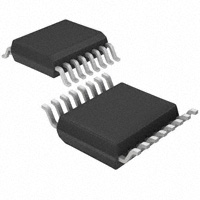
16-lead TSSOP package
The AD7745/AD7746 are a high resolution, Σ-Δ capacitance-todigital converter (CDC). The capacitance to be measured is
connected directly to the device inputs. The architecture features inherent high resolution (24-bit no missing codes, up to
21-bit effective resolution), high linearity (±0.01%), and high
accuracy (±4 fF factory calibrated). The AD7745/AD7746
capacitance input range is ±4 pF (changing), while it can accept
up to 17 pF common-mode capacitance (not changing), which
can be balanced by a programmable on-chip, digital-tocapacitance converter (CAPDAC).
The AD7745 has one capacitance input channel, while the
AD7746 has two channels. Each channel can be configured as
single-ended or differential. The AD7745/AD7746 are designed
for floating capacitive sensors. For capacitive sensors with one
plate connected to ground, the AD7747 is recommended.
The parts have an on-chip temperature sensor with a resolution
of 0.1°C and accuracy of ±2°C. The on-chip voltage reference
and the on-chip clock generator eliminate the need for any
external components in capacitive sensor applications. The
parts have a standard voltage input, which together with the
differential reference input allows easy interface to an external
temperature sensor, such as an RTD, thermistor, or diode.
APPLICATIONS
Automotive, industrial, and medical systems for
Pressure measurement
Position sensing
Level sensing
Flowmeters
Humidity sensing
Impurity detection
The AD7745/AD7746 have a 2-wire, I2C-compatible serial
interface. Both parts can operate with a single power supply
from 2.7 V to 5.25 V. They are specified over the automotive
temperature range of –40°C to +125°C and are housed in a
16-lead TSSOP package.
FUNCTIONAL BLOCK DIAGRAMS
VDD
TEMP
SENSOR
CLOCK
GENERATOR
VDD
VIN(+)
VIN(–)
MUX
CIN1(+)
CIN1(–)
24-BIT Σ-∆
MODULATOR
TEMP
SENSOR
AD7745
DIGITAL
FILTER
I2C
SERIAL
INTERFACE
SDA
SCL
CLOCK
GENERATOR
AD7746
VIN(+)
VIN(–)
MUX
CIN1(+)
CIN1(–)
24-BIT Σ-∆
MODULATOR
DIGITAL
FILTER
I2C
SERIAL
INTERFACE
SDA
SCL
CIN2(+)
CIN2(–)
CONTROL LOGIC
CALIBRATION
CAP DAC
RDY
RDY
CAP DAC
VOLTAGE
REFERENCE
EXCB
REFIN(+) REFIN(–)
GND
Figure 1.
EXC1
05468-001
EXCITATION
VOLTAGE
REFERENCE
EXCITATION
EXC2
REFIN(+) REFIN(–)
GND
Figure 2.
Rev. 0
Information furnished by Analog Devices is believed to be accurate and reliable.
However, no responsibility is assumed by Analog Devices for its use, nor for any
infringements of patents or other rights of third parties that may result from its use.
Specifications subject to change without notice. No license is granted by implication
or otherwise under any patent or patent rights of Analog Devices. Trademarks and
registered trademarks are the property of their respective owners.
One Technology Way, P.O. Box 9106, Norwood, MA 02062-9106, U.S.A.
Tel: 781.329.4700
www.analog.com
Fax: 781.461.3113
© 2005 Analog Devices, Inc. All rights reserved.
05468-002
CAP DAC
EXCA
CONTROL LOGIC
CALIBRATION
CAP DAC
�AD7745/AD7746
TABLE OF CONTENTS
Specifications..................................................................................... 3
Cap Gain Calibration Register.................................................. 19
Timing Specifications....................................................................... 5
Volt Gain Calibration Register ................................................. 19
Absolute Maximum Ratings............................................................ 6
Circuit Description......................................................................... 20
Pin Configurations and Function Descriptions ........................... 7
Overview ..................................................................................... 20
Typical Performance Characteristics ............................................. 8
Capacitance-to-Digital Converter ........................................... 20
Output Noise and Resolution Specifications .............................. 11
Excitation Source........................................................................ 20
Serial Interface ................................................................................ 12
CAPDAC ..................................................................................... 21
Read Operation........................................................................... 12
Single-Ended Capacitive Input................................................. 21
Write Operation.......................................................................... 12
Differential Capacitive Input .................................................... 21
AD7745/AD7746 Reset ............................................................. 13
Parasitic Capacitance to Ground.............................................. 22
General Call................................................................................. 13
Parasitic Resistance to Ground................................................. 22
Register Descriptions ..................................................................... 14
Parasitic Parallel Resistance ...................................................... 22
Status Register ............................................................................. 15
Parasitic Serial Resistance ......................................................... 23
Cap Data Register....................................................................... 15
Capacitive Gain Calibration ..................................................... 23
VT Data Register ........................................................................ 15
Capacitive System Offset Calibration ...................................... 23
Cap Set-Up Register ................................................................... 16
Internal Temperature Sensor .................................................... 23
VT Set-Up Register .................................................................... 16
External Temperature Sensor ................................................... 24
EXC Set-Up Register .................................................................. 17
Voltage Input............................................................................... 24
Configuration Register .............................................................. 18
VDD Monitor ................................................................................ 24
Cap DAC A Register................................................................... 19
Typical Application Diagram.................................................... 24
Cap DAC B Register................................................................... 19
Outline Dimensions ....................................................................... 25
Cap Offset Calibration Register................................................ 19
Ordering Guide .......................................................................... 25
REVISION HISTORY
4/05—Revision 0: Initial Version
Rev. 0 | Page 2 of 28
�AD7745/AD7746
SPECIFICATIONS
VDD = 2.7 V to 3.6 V or 4.75 V to 5.25 V; GND = 0 V; EXC = 32 kHz; EXC = ±VDD/2; –40°C to +125°C, unless otherwise noted.
Table 1.
Parameter
CAPACITIVE INPUT
Conversion Input Range
Integral Nonlinearity (INL)2
No Missing Codes2
Resolution, p-p
Resolution Effective
Output Noise, rms
Absolute Error3
Offset Error2, 4
System Offset Calibration Range2
Offset Drift vs. Temperature
Gain Error5
Gain Drift vs. Temperature2
Allowed Capacitance to GND2
Power Supply Rejection
Normal Mode Rejection
Channel-to-Channel Isolation
CAPDAC
Full Range
Resolution6
Drift vs. Temperature2
EXCITATION
Frequency
Voltage Across Capacitance
Min
Max
±4.096
±0.01
24
16.5
19
2
±4
32
±1
–28
–1
0.02
–26
0.08
–24
60
1
0.3
65
55
70
17
24
21
164
26
0.1
±0.5
±2
Unit
Test Conditions/Comments
pF1
% of FSR
Bit
Bit
Bit
aF/√Hz
fF1
aF1
Factory calibrated
pF
aF/°C
% of FS
ppm of FS/°C
pF
fF/V
dB
dB
dB
28
pF
fF
ppm of FS/°C
50 MΩ)
PARASITIC CAPACITANCE TO GROUND
CGND1
CIN
CDC
VDD ≥ 2.7 V: IGND < 30 nA (that is, RGND > 100 MΩ)
A higher leakage current to ground results in a gain error, an
offset error, and a nonlinearity error. See the typical
performance characteristics shown in Figure 12 and Figure 13.
DATA
PARASITIC PARALLEL RESISTANCE
CX
CIN
Figure 36. Parasitic Capacitance to Ground
CX
The CDC architecture used in the AD7745/AD7746 measures
the capacitance CX connected between the EXC pin and the
CIN pin. In theory, any capacitance CP to ground should not
affect the CDC result (see Figure 36).
The practical implementation of the circuitry in the chip
implies certain limits and the result is gradually affected by
capacitance to ground. See the allowed capacitance to GND in
the specification table for CIN and excitation. Also see the
typical performance characteristics shown in Figure 9, Figure
10, and Figure 11.
CDC
DATA
RP
EXC
05468-022
EXC
05468-012
CGND2
Figure 38. Parasitic Parallel Resistance
The AD7745/AD7746 CDC measures the charge transfer
between EXC pin and CIN pin. Any resistance connected in
parallel to the measured capacitance CX (see Figure 38), such as
the parasitic resistance of the sensor, also transfers charge.
Therefore, the parallel resistor is seen as an additional
capacitance in the output data. The equivalent parallel
capacitance (or error caused by the parallel resistance) can be
approximately calculated as
CP =
1
RP × FEXC × 4
Where RP is the parallel resistance and CEXC is the excitation
frequency. See the typical performance characteristics shown in
Figure 14.
Rev. 0 | Page 22 of 28
�AD7745/AD7746
The offset calibration register is reloaded by the default value at
power-on or after reset. Therefore, if the offset calibration is not
repeated after each system power-up, the calibration coefficient
value should be stored by the host controller and reloaded as
part of the AD7745/AD7746 setup.
RS1
CIN
CDC
DATA
RS2
05468-023
CX
EXC
Figure 39. Parasitic Serial Resistance
The AD7745/AD7746 CDC result is affected by a resistance in
series with the measured capacitance. The total serial resistance,
which refers to RS1 + RS2 on Figure 39, should be less than 1 kΩ
for the specified performance. See typical performance characteristics shown in Figure 15.
On the AD7746, the register is shared by the two capacitive
channels. If the capacitive channels need to be offset calibrated
individually, the host controller software should read the
AD7746 capacitive offset calibration register values after
performing the offset calibration on individual channels and
then reload the values back to the AD7746 before executing a
conversion on a different channel.
INTERNAL TEMPERATURE SENSOR
INTERNAL TEMPERATURE SENSOR
CLOCK
GENERATOR
CAPACITIVE GAIN CALIBRATION
The AD7745/AD7746 gain is factory calibrated for the full scale
of ±4.096 pF in the production for each part individually. The
factory gain coefficient is stored in a one-time programmable
(OTP) memory and is copied to the capacitive gain register at
power-up or after reset.
The gain can be changed by executing a capacitance gain
calibration mode, for which an external full-scale capacitance
needs to be connected to the capacitance input, or by writing a
user value to the capacitive gain register. This change would be
only temporary and the factory gain coefficient would be
reloaded back after power-up or reset. The part is tested and
specified only for use with the default factory calibration
coefficient.
VDD
N×I
I
∆VBE
24-BIT Σ-∆
MODULATOR
DIGITAL DATA
FILTER
AND
SCALING
VOLTAGE
REFERENCE
05468-040
PARASITIC SERIAL RESISTANCE
Figure 40. Internal Temperature Sensor
The temperature sensing method used in the AD7745/AD7746
is to measure a difference in ∆VBE voltage of a transistor
operated at two different currents (see Figure 40). The ∆VBE
change with temperature is linear and can be expressed as
∆VBE = (n f )
KT
× ln(N )
q
where:
CAPACITIVE SYSTEM OFFSET CALIBRATION
The capacitive offset is dominated by the parasitic offset in the
application, such as the initial capacitance of the sensor, any
parasitic capacitance of tracks on the board, and the capacitance
of any other connections between the sensor and the CDC.
Therefore, the AD7745/AD7746 are not factory calibrated for
capacitive offset. It is the user’s responsibility to calibrate the
system capacitance offset in the application.
Any offset in the capacitance input larger than ±1 pF should
first be removed using the on-chip CAPDACs. The small offset
within ±1 pF can then be removed by using the capacitance
offset calibration register.
One method of adjusting the offset is to connect a zero-scale
capacitance to the input and execute the capacitance offset
calibration mode. The calibration sets the midpoint of the
±4.096 pF range (that is, Output Code 0x800000) to that
zero-scale input.
K is Boltzmann’s constant (1.38 × 10⁻²³).
T is the absolute temperature in Kelvin.
q is the charge on the electron (1.6 × 10⁻¹⁹ coulombs).
N is the ratio of the two currents.
nf is the ideality factor of the thermal diode.
The AD7745/AD7746 uses an on-chip transistor to measure the
temperature of the silicon chip inside the package. The Σ-Δ
ADC converts the ∆VBE to digital, the data are scaled using
factory calibration coefficients, thus the output code is
proportional to temperature:
Temperatur e(°C ) =
Code
− 4096
2048
The AD7745/AD7746 has a low power consumption resulting
in only a small effect due to the part self-heating (less than
0.5°C at VDD = 5 V).
Another method would be to calculate and write the offset calibration register value, the LSB is value 31.25 aF (4.096 pF/217).
Rev. 0| Page 23 of 28
�AD7745/AD7746
If the capacitive sensor can be considered to be at the same
temperature as the AD7745/AD7746 chip, the internal
temperature sensor can be used as a system temperature sensor.
That means the complete system temperature drift
compensation can be based on the AD7745/AD7746 internal
temperature sensor without need for any additional external
components. See the typical performance characteristics in
Figure 18.
VOLTAGE INPUT
VDD
ANALOG TO DIGITAL CONVERTER
(ADC)
CLOCK
GENERATOR
VIN(+)
EXTERNAL TEMPERATURE SENSOR
RTD
DATA
24-BIT Σ-∆
MODULATOR
VIN(–)
DIGITAL
FILTER
VDD
I ... N × I
REFIN(+)
CLOCK
GENERATOR
VOLTAGE
REFERENCE
RREF
REFIN(–)
2N3906
∆VBE
RS1 VIN (+)
RS2 VIN (–)
24-BIT Σ-∆
MODULATOR
DIGITAL DATA
FILTER
AND
SCALING
Figure 42. Resistive Temperature Sensor Connected to the Voltage Input
The AD7745/AD7746 Σ-Δ core can work as a high resolution
(up to 21 ENOB) classic ADC with a fully differential voltage
input. The ADC can be used either with the on-chip high
precision, low drift, 1.17 V voltage reference, or an external
reference connected to the fully differential reference input pins.
05468-041
VOLTAGE
REFERENCE
GND
Figure 41. Transistor as an External Temperature Sensor
The AD7745/AD7746 provide the option of using an external
transistor as a temperature sensor in the system. The ∆VBE
method, which is similar to the internal temperature sensor
method, is used. However, it is modified to compensate for the
serial resistance of connections to the sensor. Total serial
resistance (RS1 + RS2 in Figure 41) up to 100 Ω is compensated.
The VIN(–) pin must be grounded for proper external
temperature sensor operation.
The voltage and reference inputs are continuously sampled by a
Σ-Δ modulator during the conversion. Therefore, the input
source impedance should be kept low. See the application
example in Figure 42.
VDD MONITOR
Along with converting external voltages, the AD7745/AD7746
Σ-Δ ADC can be used for monitoring the VDD voltage. The
voltage from the VDD pin is internally attenuated by 6.
The AD7745/AD7746 are factory calibrated for
Transistor 2N3906 with the ideality factor nf = 1.008.
See the typical performance characteristics shown
in Figure 19.
TYPICAL APPLICATION DIAGRAM
0.1µF
+
3V/5V
POWER SUPPLY
10µF
10kΩ
VDD
TEMP
SENSOR
CLOCK
GENERATOR
10kΩ
HOST
SYSTEM
AD7745
VIN(+)
SDA
VIN(–)
MUX
CIN1(+)
24-BIT Σ-∆
MODULATOR
DIGITAL
FILTER
I2C
SERIAL
INTERFACE
SCL
CIN1(–)
CONTROL LOGIC
CALIBRATION
CAP DAC
RDY
CAP DAC
EXCA
05468-042
EXTERNAL
TEMPERATURE
SENSOR
RT
VOLTAGE
REFERENCE
EXCITATION
REFIN(+) REFIN(–)
GND
Figure 43. Basic Application Diagram for a Differential Capacitive Sensor
Rev. 0 | Page 24 of 28
05468-008
EXCB
�AD7745/AD7746
OUTLINE DIMENSIONS
5.10
5.00
4.90
16
9
4.50
4.40
4.30
6.40
BSC
1
8
PIN 1
1.20
MAX
0.15
0.05
0.20
0.09
0.65
BSC
0.30
0.19
COPLANARITY
0.10
8°
0°
SEATING
PLANE
0.75
0.60
0.45
COMPLIANT TO JEDEC STANDARDS MO-153-AB
Figure 44. 16-Lead Thin Shrink Small Outline Package [TSSOP]
(RU-16)
Dimensions shown in millimeters
ORDERING GUIDE
Model
AD7745ARUZ1
AD7745ARUZ-REEL1
AD7745ARUZ-REEL71
AD7746ARUZ1
AD7746ARUZ-REEL1
AD7746ARUZ-REEL71
EVAL-AD7746EB
1
Temperature Range
–40°C to +125°C
–40°C to +125°C
–40°C to +125°C
–40°C to +125°C
–40°C to +125°C
–40°C to +125°C
Package Description
16-Lead TSSOP
16-Lead TSSOP
16-Lead TSSOP
16-Lead TSSOP
16-Lead TSSOP
16-Lead TSSOP
Evaluation Board
Z = Pb-free part.
Rev. 0 | Page 25 of 28
Package Option
RU-16
RU-16
RU-16
RU-16
RU-16
RU-16
�AD7745/AD7746
NOTES
Rev. 0 | Page 26 of 28
�AD7745/AD7746
NOTES
Rev. 0 | Page 27 of 28
�AD7745/AD7746
NOTES
Purchase of licensed I2C components of Analog Devices or one of its sublicensed Associated Companies conveys a license for the purchaser under the Philips I2C
Patent Rights to use these components in an I2C system, provided that the system conforms to the I2C Standard Specification as defined by Philips.
© 2005 Analog Devices, Inc. All rights reserved. Trademarks and
registered trademarks are the property of their respective owners.
C05468-0-4/05(0)
Rev. 0 | Page 28 of 28
�