One Technology Way · P.O. Box 9106 · Norwood, MA 02062-9106 · Tel: 781.329.4700 · Fax: 781.461.3113 · www.analog.com
EVALUATING THE AD9683/AD6677
ANALOG-TO-DIGITAL CONVERTERS
Preface
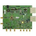
This user guide describes the AD9683 and AD6677 evaluation boards; AD9683-170EBZ,
AD9683-250EBZ, and AD6677EBZ; which provide all of the support circuitry required to operate these
parts in their various modes and configurations. The application software used to interface with the
devices is also described.
The AD9683 and AD6677 data sheets provide additional information and should be consulted when
using the evaluation board. All documents and software tools are available at
www.analog.com/hsadcevalboard. For additional information or questions, send an email to
highspeed.converters@analog.com.
Typical Measurement Setup
Rev 05 Jun 2013 16:37 | Page 1
�Figure 1. Evaluation Board Connection—AD9683-170EBZ, AD9683-250EBZ, or AD6677EBZ (on Left)
and HSC-ADC-EVALDZ (on Right)
Features
●
●
●
●
●
●
Full featured evaluation board for the AD9683/AD6677
SPI interface for setup and control
External, on-board oscillator, or AD9525 clocking option
Balun/transformer or amplifier input drive option
On-board LDO regulator needing a single external 6 V, 2 A dc supply
VisualAnalog® and SPI controller software interfaces
Helpful Documents
●
●
●
●
●
●
AD9683 or AD6677 data sheet
High speed ADC FIFO evaluation kit (HSC-ADC-EVALCZ)
AN-905 Application Note, VisualAnalogTM Converter Evaluation Tool Version 1.0 User Manual
AN-878 Application Note, High Speed ADC SPI Control Software
AN-877 Application Note, Interfacing to High Speed ADCs via SPI
AN-835 Application Note, Understanding High Speed ADC Testing and Evaluation
Equipment Needed
●
●
●
●
●
●
●
●
Analog signal source and antialiasing filter
Sample clock source (if not using the on-board oscillator)
(1) 6.0 V, 2.5 A switching power supply, CUI EPS060250UH-PHP-SZ provided
(1) 12.0V, 3.3 A switching power supply, V-Infinity ETSA120330UDC-PFP-SZ provided
PC running Windows®
USB 2.0 port
AD9683-170EBZ, AD9683-250EBZ, or AD6677EBZ board
HSC-ADC-EVALDZ FPGA-based data capture kit
Getting Started
This section provides quick start procedures for using the AD9683-170EBZ, AD9683-250EBZ, or
AD6677EBZ board. Both the default and optional settings are described.
Rev 05 Jun 2013 16:37 | Page 2
�Configuring the Board
Before using the software for testing, configure the evaluation board as follows:
1. Connect the evaluation board to the data capture board, as shown in Figure 1.
2. Connect one 6 V, 2.5 A switching power supply (such as the CUI, Inc., EPS060250UH-PHP-SZ that is
supplied) to the AD9683-170EBZ, AD9683-250EBZ, or AD6677.
3. Connect one 12 V, 3.3 A switching power supply (such as the supplied V-Infinity
ETSA120330UDC-PFP-SZ) to the HSC-ADC-EVALCZ board.
4. Connect the HSC-ADC-EVALDZ board (P702) to the PC using a USB cable.
5. On the ADC evaluation board, confirm that the jumpers are installed at P202, P209, P204, P205,
P206, and P210 as shown in Figure 2 and Table 1.
6. On the ADC evaluation board, use a clean signal generator with low phase noise to provide an
input signal to the AD9683 analog input. Use a 1 m, shielded, RG-58, 50 Ω coaxial cable to connect
the signal generator. For best results, use a narrow-band, band-pass filter with 50 Ω terminations
and an appropriate center frequency. (Analog Devices, Inc., uses TTE, Allen Avionics, and K&L
band-pass filters.)
Evaluation Board Hardware
The evaluation board provides the support circuitry required to operate the AD9683 and AD6677 in
their various modes and configurations. Figure 1 shows the typical bench characterization setup used
to evaluate AC performance. It is critical that the signal sources used for the analog input and clock
have very low phase noise (
很抱歉,暂时无法提供与“AD9683-250EBZ”相匹配的价格&库存,您可以联系我们找货
免费人工找货