AD9707/AD9706/AD9705/AD9704 EVB
Quick Start Guide
One Technology Way • P.O. Box 9106 • Norwood, MA 02062‐9106, U.S.A. • Tel: 781.329.4700 • Fax: 781.461.3113 • www.analog.com
Getting Started with the AD9707/AD9706/AD9705/AD9704 Evaluation Board and
Software
WHAT’S IN THE BOX
EXAMPLE EQUIPMENT LIST
AD9707/AD9706/AD9705/AD9704‐EBZ Evaluation Board
Mini‐USB Cable
AD9707 Evaluation Board CD
DAC Clock Source: R&S SML 02
Spectrum Analyzer: Agilent E4400
PC: Windows PC with USB 2.0 ports
DPG2: Data Pattern Generator series 2
QUICK START PROCEDURE
INITIAL SETUP
1.
2.
3.
4.
5.
Install AD970x software and support files on your PC.
Make the connections described in the Basic Hardware Setup below. The Evaluation Board will be powered up when the
USB cable is plugged into connector XP2.
If operating the AD970x in PIN mode install JP11. If operating the AD970x in SPI mode register read/write press, and
then release the AD9707 RESET button on the EVB. One of these two steps must be taken for the AD970x to be
guaranteed to be in its default state.
Turn on the 175Mhz clock signal source.
Start the AD970x evaluation software control panel GUI and press the green GO button. The GUI display should look like
Figure 6.
Getting the DAC to Output a 20Mhz sine wave
6.
7.
Start the DPG control software. The DPG software will display the DAC part number in the Evaluation Board window
In the port configuration tab select LVCMOS 3.3V DCO . A green bar will appear in the configuration progress window.
Once configuration is complete a clock frequency close to the clock generator frequency will appear in the Data Clock
Frequency window.
8. Next select single tone generation from the Add Generated Waveforms pull down menu.
9. Set the sample rate to 175Mhz, Set the desired frequency to 20Mhz, Set DAC resolution to the DAC’s number of bits 14
for AD9707 for example . Check the Unsigned Data box.
10. Select the tone in the Data Vector pull down menu.
11. Press the download arrow then the green arrow when it appears to start waveform generation.
12. You should see the spectrum shown in Figure 2.
Information furnished by Analog Devices is believed to be accurate and reliable. However, no
responsibility is assumed by Analog Devices for its use, nor for any infringements of patents or other
rights of third parties that may result from its use. Specifications subject to change without notice. No
license is granted by implication or otherwise under any patent or patent rights of Analog Devices.
Trademarks and registered trademarks are the property of their respective owners.
One Technology Way, P.O. Box 9106, Norwood, MA 02062‐9106, U.S.A.
Tel: 781.329.4700
www.analog.com
Fax: 781.461.3113
©2010 Analog Devices, Inc. All rights reserved.
�Quick Start Guide
AD9707/AD9706/AD9705/AD9704‐EBZ
Basic Hardware Set‐Up
Equipment
Connections to AD9707/AD9706/AD9705/AD9704 Eval Board
DPG2
Install the EVB in the DPG2 system Figure 5
Signal Source Clk
J10 CLK IN , Set source to 175MHz, 3dBm output
PC USB Cable
XP2, USB port powers the EVB and provides the data interface from the PC to
the PIC processor
Spectrum Analyzer
S4 IOUT_A
Rev. A | Page 2 of 8
�Quick Start Guide
AD9707/AD9706/AD9705/AD9704‐EBZ
EVALUATION SYSTEM
AD9707 EVALUATION BOARD
The AD9707, AD9706, AD9705 and AD9704 are single, high performance CMOS TxDACs. Their evaluation board includes a PIC
18F4550 processor programmed to function as an interface between the PC USB and the SPI port of the device. And an AD9512
clock chip that takes in an up to 175Mhz signal from the clock source and provides the CLK /CLK‐ input to the AD970x. The EVB
is powered by the USB supply rail provided by the PC USB interface.
Figure 1: AD9707/AD9706/AD9705/AD9704 evaluation board
Figure 2: Spectrum analyzer Display of Output
Rev. A | Page 3 of 8
�Quick Start Guide
AD9707/AD9706/AD9705/AD9704‐EBZ
AD9707/AD9706/AD9705/AD9704 EVALUATION SOFTWARE GUI
The AD9707/AD9706/AD9705/AD9704 Evaluation Board companion software will display the control panel GUI shown in
Figure 3. The content of on‐chip registers is shown in the “AD970x readback array” section of the GUI. Figure 3 displays the state
of the registers at power up before the SPI software is run. The GUI includes control panels for:
‐
‐
‐
‐
‐
Power Down that allows manual operation of
o Power Down and Sleep Features
o Clock Off Control
o External Reference Selection
SPI Interface Setup
DAC Data Interface and Clocking
The built‐in Self Calibration Feature
The AD9512 Clock Chip included in the EVB
Figure 3: AD9707/AD9706/AD9705/AD9704 evaluation software Control Panel GUI
Data Pattern Generator Hardware and Software
Figure 5 is block diagram and photograph of the bench setup for this product. The AD9707/AD9706/AD9705/AD9704
Evaluation Board plugs into the Data Pattern Generator DPG as shown in the photograph. The DPG provides real time data
patterns to the product being evaluated at the DAC sampling frequency.
DPG software presents a GUI environment Figure 4 that enables users to generate a wide selection of built in digital signals as
well as user generated waveforms. DPG signals include:
‐
‐
‐
‐
DC waveform, Noise waveforms: Gaussian, Uniform, White
Sine Waves
Cable waveforms: US/Europe Multi‐channel 64 or 256 QAM
Wireless waveforms: GSM: GMSK,EDGE/8PSK, WCDMA, LTE, WiMax
©2010 Analog Devices, Inc. All rights reserved. Trademarks and
registered trademarks are the property of their respective owners.
D00000‐0‐1/0
�Quick Start Guide
AD9707/AD9706/AD9705/AD9704‐EBZ
Figure 4: DPG GUI
HARDWARE SETUP
‐
‐
‐
‐
The 5V PC USB supply rail powers the evaluation board.
The SPI register access interface connects to the evaluation board through the PC USB as well.
A 175MHz sinusoidal clock with an amplitude of 3dBm is used.
DAC current outputs are converted from differential to single ended using an RF transformer on
the EVB. The output at S4 is capable of driving 50 ohms.
©2010 Analog Devices, Inc. All rights reserved. Trademarks and
registered trademarks are the property of their respective owners.
D00000‐0‐1/0
�Quick Start Guide
AD9707/AD9706/AD9705/AD9704‐EBZ
Figure 5: Bench set up
Figure 6: AD970x SPI evaluation software
©2010 Analog Devices, Inc. All rights reserved. Trademarks and
registered trademarks are the property of their respective owners.
D00000‐0‐1/0
�Quick Start Guide
AD9707/AD9706/AD9705/AD9704‐EBZ
©2010 Analog Devices, Inc. All rights reserved. Trademarks and
registered trademarks are the property of their respective owners.
D00000‐0‐1/0
�Quick Start Guide
AD9707/AD9706/AD9705/AD9704‐EBZ
©2010 Analog Devices, Inc. All rights reserved. Trademarks and
registered trademarks are the property of their respective owners.
D00000‐0‐1/0
�
很抱歉,暂时无法提供与“AD9706-DPG2-EBZ”相匹配的价格&库存,您可以联系我们找货
免费人工找货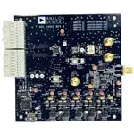


 工商网监
湘ICP备2023018690号
工商网监
湘ICP备2023018690号
