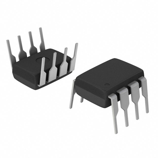
ADM709RAN

ADM709RAN

  • 厂商:

    AD(亚德诺)

  • 封装:

    DIP8

  • 描述:

    IC SUPERVISOR 1 CHANNEL 8DIP

  • 详情介绍
  • 数据手册
  • 价格&库存
ADM709RAN 数据手册
a FEATURES Precision Supply Voltage Monitor +5 V, +3.3 V, +3 V Power Supply Monitor 35 A Quiescent Current 140 ms (min) Power-On Reset Pulse Low Cost 8-Pin DIP/SO Packages Upgrade for MAX709 APPLICATIONS Microprocessor Systems Computers Controllers Intelligent Instruments Critical P Monitoring Automotive Systems Critical P Power Monitoring GENERAL DESCRIPTION VCC VTH Power Supply Monitor with Reset ADM709 FUNCTIONAL BLOCK DIAGRAM ADM709 RESET GENERATOR RESET GND VCC VCC ADM709 RESET GND RESET µP GND The ADM709 contains a power supply monitor which generates a system reset during power-up, power-down and brownout conditions. When VCC falls below the reset threshold, RESET goes low and holds the µP in reset. On power-up the RESET output is held low for 140 ms after VCC rises above the threshold. The RESET output remains operational with VCC as low as 1 V. Three supply-voltage threshold levels are available suitable for +5 V, +3.3 V and for +3 V supply monitoring. The actual reset voltage threshold is given below. The ADM709 is available in 8-pin DIP and SOIC packages. Table I. Reset Threshold Typical Operating Circuit ORDERING GUIDE Model ADM709LAN ADM709LAR ADM709MAN ADM709MAR ADM709TAN ADM709TAR ADM709SAN ADM709SAR ADM709RAN ADM709RAR Reset Threshold 4.65 V 4.65 V 4.40 V 4.40 V 3.08 V 3.08 V 2.93 V 2.93 V 2.63 V 2.63 V Temperature Range –40°C to +85°C –40°C to +85°C –40°C to +85°C –40°C to +85°C –40°C to +85°C –40°C to +85°C –40°C to +85°C –40°C to +85°C –40°C to +85°C –40°C to +85°C Package Option* N-8 SO-8 N-8 SO-8 N-8 SO-8 N-8 SO-8 N-8 SO-8 Suffix L M T S R Voltage (V) 4.65 4.40 3.08 2.93 2.63 *N = Plastic DIP; SO = SOIC. REV. 0 Information furnished by Analog Devices is believed to be accurate and reliable. However, no responsibility is assumed by Analog Devices for its use, nor for any infringements of patents or other rights of third parties which may result from its use. No license is granted by implication or otherwise under any patent or patent rights of Analog Devices. © Analog Devices, Inc., 1995 One Technology Way, P.O. Box 9106, Norwood. MA 02062-9106, U.S.A. Tel: 617/329-4700 Fax: 617/326-8703 ADM709–SPECIFICATIONS (V Parameter VCC Operating Voltage Range Supply Current Min 1.0 1.2 35 35 65 65 4.5 4.25 3.00 2.85 2.55 4.65 4.40 3.08 2.93 2.63 20 140 280 Typ CC = Full Operating Range, TA = TMIN to TMAX unless otherwise noted) Max 5.5 5.5 85 110 150 200 4.75 4.50 3.15 3.00 2.70 Units V V µA µA µA µA V V V V V µs 380 0.3 0.4 0.3 0.4 ms V V V V V V Test Conditions/Comments TA = 0°C to +70°C TA = –40°C to +85°C VCC < 3.6 V, TA = 0°C to +70°C VCC < 3.6 V, TA = –40°C to +85°C VCC < 5.5 V, TA = 0°C to +70°C VCC < 5.5 V, TA = –40°C to +85°C ADM709L ADM709M ADM709T ADM709S ADM709R VCC = Reset Threshold max–min VCC = Reset Threshold max, VCC Rising ADM709R/S/T, ISINK = 1.2 mA. VCC = Reset Threshold min ADM709L/M, ISINK = 3.2 mA. VCC = Reset Threshold min ISINK = 50 µA. VCC ≥ 1.0 V ISINK = 100 µA. VCC ≥ 1.2 V ADM709R/S/T, ISOURCE = 500 µA, VCC ≥ Reset Threshold max ADM709L/M, ISOURCE = 800 µA, VCC ≥ Reset Threshold max Reset Threshold VCC to RESET Delay RESET Active Time-Out Period RESET Output Voltage 0.8 × VCC VCC–1.5 V Specifications subject to change without notice. ABSOLUTE MAXIMUM RATINGS* (TA = +25°C unless otherwise noted) PIN FUNCTION DESCRIPTION VCC . . . . . . . . . . . . . . . . . . . . . . . . . . . . . . . . . –0.3 V to +6 V RESET Output . . . . . . . . . . . . . . . . . . . –0.3 V to VCC + 0.3 V VCC Input Current . . . . . . . . . . . . . . . . . . . . . . . . . . . . 20 mA RESET Output Current . . . . . . . . . . . . . . . . . . . . . . . . 20 mA Power Dissipation, N-8 DIP . . . . . . . . . . . . . . . . . . . . 727 mW θJA Thermal Impedance . . . . . . . . . . . . . . . . . . . . . 135°C/W Power Dissipation, SO-8 SOIC . . . . . . . . . . . . . . . . . . 470 mW θJA Thermal Impedance . . . . . . . . . . . . . . . . . . . . . 110°C/W Operating Temperature Range Industrial ( A Version) . . . . . . . . . . . . . . . . . –40°C to +85°C Lead Temperature (Soldering, 10 secs) . . . . . . . . . . . . +300°C Vapor Phase (60 secs) . . . . . . . . . . . . . . . . . . . . . . . . . +215°C Infrared (15 secs) . . . . . . . . . . . . . . . . . . . . . . . . . . . . . +220°C Storage Temperature Range . . . . . . . . . . . . . –65°C to +150°C ESD Rating . . . . . . . . . . . . . . . . . . . . . . . . . . . . . . . . . . . >5 kV * Mnemonic Pin No. NC VCC RESET 1, 4, 5, 6, 8 2 7 Function No Connect Pins. +5 V, +3.3 V, +3 V Power Supply Input. Logic Output. It remains low while VCC is below the reset threshold voltage and for 280 ms (typ) after VCC rises above the threshold. Ground, 0 V. GND 3 PIN CONFIGURATION Stresses above those listed under “Absolute Maximum Ratings” may cause permanent damage to the device. This is a stress rating only and functional operation of the device at these or any other conditions above those listed in the operational sections of this specification is not implied. Exposure to absolute maximum ratings for extended periods of time may affect device reliability. NC 1 VCC 2 GND 3 NC 4 8 NC RESET NC NC ADM709 TOP VIEW (Not to Scale) 7 6 5 NC = NO CONNECT –2– REV. 0 ADM709 ADM709 VCC VTH RESET GENERATOR RESET RESET at Voltages < 1 V GND The ADM709 RESET output is guaranteed to operate with supply voltages as low as 1 V. If it is desired that the RESET output remains low below 1 V, then a pull-down resistor should be connected between the RESET output and GND. A resistor of 100 kΩ is suitable. This is illustrated in Figure 5. Figure 1. Functional Block Diagram ADM709 RESET VCC VCC R1 GND ADM709 RESET GND RESET µP GND Figure 5. RESET Valid @ VCC < 1 V Glitch Immunity Figure 2. Typical Operating Circuit CIRCUIT INFORMATION RESET Output The ADM709 is immune to short transients which may occur on the VCC line. This is important so that spurious resets are not generated as a result of minor glitches on the power supply. Additional glitch immunity may be obtained by connecting a capacitor (0.1 µF or greater) as close as possible to the VCC pin on the device. Microprocessors with Bidirectional I-O RESET is an active low output which provides a reset signal to the microprocessor whenever the VCC supply voltage is below the reset threshold. An internal timer holds RESET low for 140 ms after the voltage on VCC rises above the threshold. This is intended as a power-on reset signal for the processor. It allows time for the power supply and microprocessor to stabilize after power up. Similarly a power supply brownout will initiate a processor reset. On power-down, the RESET output remains low with VCC as low as 1 V. This ensures that the microprocessor is held in a stable shutdown condition as the power supply drops. VRT VRT Some microprocessors or microcontrollers such as the MC68HC11 have bidirectional reset lines. In order to avoid signal contention, a resistor of 4.7 kΩ should be connected between the ADM709 RESET output and the microcontroller RESET line. This arrangement is shown in Figure 6. +5V BUFFERED RESET VCC VCC ADM709 tRS RESET µP RESET RESET GND GND Figure 3. Power Off/On RESET Timing Figure 6. Interfacing to Microprocessors with Bidirectional RESET VCC RESET 400ms/DIV Figure 4. RESET Output vs. VCC REV. 0 –3– ADM709 OUTLINE DIMENSIONS Dimensions shown in inches and (mm). 8-Lead Plastic DIP (N-8) C2022–18–4/95 0.195 (4.95) 0.115 (2.93) 8 PIN 1 1 5 0.280 (7.11) 0.240 (6.10) 4 0.430 (10.92) 0.348 (8.84) 0.210 (5.33) MAX 0.160 (4.06) 0.115 (2.93) 0.060 (1.52) 0.015 (0.38) 0.325 (8.25) 0.300 (7.62) 0.130 (3.30) MIN SEATING PLANE 0.015 (0.381) 0.008 (0.204) 0.022 (0.558) 0.014 (0.356) 0.100 (2.54) BSC 0.070 (1.77) 0.045 (1.15) 8-Lead SOIC (SO-8) 8 5 0.1574 (4.00) 0.1497 (3.80) PIN 1 1 4 0.2440 (6.20) 0.2284 (5.80) 0.1968 (5.00) 0.1890 (4.80) 0.0098 (0.25) 0.0040 (0.10) 0.0500 (1.27) BSC 0.0688 (1.75) 0.0532 (1.35) 0.0192 (0.49) 0.0138 (0.35) 8° 0° 0.0196 (0.50) x 45 ° 0.0099 (0.25) 0.0098 (0.25) 0.0075 (0.19) 0.0500 (1.27) 0.0160 (0.41) –4– REV. 0 PRINTED IN U.S.A.
ADM709RAN
1. 物料型号: - ADM709LAN - ADM709LAR - ADM709MAN - ADM709MAR - ADM709TAN - ADM709TAR - ADM709SAN - ADM709SAR - ADM709RAN - ADM709RAR

2. 器件简介: ADM709是一款电源监控器,能够在上电、掉电和电压过低情况下生成系统复位信号。当供电电压低于复位阈值时,RESET引脚输出低电平,使微处理器保持在复位状态。上电时,RESET输出在供电电压超过阈值后保持低电平140ms。

3. 引脚分配: - 1, 4, 5, 6, 8:No Connect(无连接) - 2:Vcc(供电) - 3:GND(地) - 7:RESET(逻辑输出)

4. 参数特性: - 供电电压范围:1.0V至5.5V - 供电电流:1.2μA至110mA - 复位阈值电压:根据不同型号,范围从2.63V至4.65V - Vcc至RESET延迟:20ns至Ts(阈值最大值减最小值) - RESET活跃超时周期:140ms至380ms - RESET输出电压:0.3V至0.8xVcc

5. 功能详解: RESET为低电平有效输出,当供电电压低于复位阈值时,向微处理器提供复位信号。内部计时器在供电电压超过阈值后保持RESET低电平140ms,作为微处理器的上电复位信号。

6. 应用信息: 适用于微处理器系统、计算机、控制器、智能仪器、关键电源监控和汽车系统等关键电源监控。

7. 封装信息: ADM709提供8引脚DIP和SOIC封装。

ADM709RAN 价格&库存

很抱歉,暂时无法提供与“ADM709RAN”相匹配的价格&库存,您可以联系我们找货

免费人工找货