EVAL-ADP2311 User Guide
UG-653
One Technology Way • P.O. Box 9106 • Norwood, MA 02062-9106, U.S.A. • Tel: 781.329.4700 • Fax: 781.461.3113 • www.analog.com
Evaluation Board for the ADP2311, Dual, 1 A, 18 V Synchronous Step-Down
Regulator with Fail-Safe Voltage Monitoring
FEATURES
GENERAL DESCRIPTION
Input voltage: 4.5 V to 18 V
±1.0% output accuracy
Integrated MOSFET: 110 mΩ/60 mΩ typical
Continuous output current: 1 A/1 A
Power fail comparator generates warning
Power-on reset with programmable delay timer
Adjustable voltage monitor for power-down
Watchdog refresh input
Dual phase with 180° out of phase operation
Fixed switching frequency: 300 kHz
Internal compensation and soft start
Stable with low effective series resistance (ESR) output
ceramic capacitors
Precision enable input
Power feedback during power off
Undervoltage lockout (UVLO), overcurrent protection (OCP),
overvoltage protection (OVP), and thermal shutdown (TSD)
The ADP2311 evaluation board is a complete, dual, 1 A step-down
regulator solution that allows users to evaluate the performance of
the ADP2311 with a near ideal printed circuit board (PCB) layout.
The outputs of the ADP2311 evaluation board are preset to 1.2 V
and 3.3 V for Channel 1 and Channel 2, respectively. The VIN
threshold of the power fail input is set at 8.99 V. Different
output and power fail input voltages can be achieved by
changing the appropriate passive components.
Full details on the ADP2311 dual regulator are provided in the
ADP2311 data sheet, available from Analog Devices, Inc., which
should be consulted in conjunction with this user guide.
11995-001
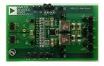
ADP2311 EVALUATION BOARD
Figure 1.
PLEASE SEE THE LAST PAGE FOR AN IMPORTANT
WARNING AND LEGAL TERMS AND CONDITIONS.
Rev. 0 | Page 1 of 8
�UG-653
EVAL-ADP2311 User Guide
TABLE OF CONTENTS
Features .............................................................................................. 1
Evaluation Board Schematic and Artwork.....................................5
General Description ......................................................................... 1
ADP2311 Evaluation Board Schematic ......................................5
ADP2311 Evaluation Board ............................................................ 1
PCB Layout ....................................................................................6
Revision History ............................................................................... 2
Ordering Information .......................................................................8
Using the Evaluation Board............................................................. 3
Bill of Materials ..............................................................................8
Powering Up the Evaluation Board ............................................ 3
Measuring Evaluation Board Performance .................................. 3
Modifying the Evaluation Board ................................................ 4
REVISION HISTORY
3/14—Revision 0: Initial Version
Rev. 0 | Page 2 of 8
�EVAL-ADP2311 User Guide
UG-653
USING THE EVALUATION BOARD
POWERING UP THE EVALUATION BOARD
Turning On the Evaluation Board
The ADP2311 evaluation board is supplied fully assembled and
tested. Before applying power to the evaluation board, follow the
procedures in this section.
When the power source and load are connected to the evaluation
board, it can be powered for operation.
Jumper J20 Setting (Enable)
1.
2.
3.
Jumper J20 is used to control the ADP2311. Use one of the
following methods to enable or to disable the device:
•
•
To enable the ADP2311, short the middle pin of J20 (EN)
to high.
To disable the ADP2311, short the middle pin of J20 (EN)
to low.
Input Power Source
If the input power source includes a current meter, use that meter
to monitor the input current. Connect the positive terminal of
the power source to J4 (VIN) of the evaluation board, and
connect the negative terminal of the power source to J6 (GND) of
the evaluation board.
If the power source does not include a current meter, connect a
current meter in series with the input source voltage. Connect the
positive lead (+) of the power source to the positive (+) ammeter
terminal, the negative lead (−) of the power source to J6 (GND),
and the negative lead (−) of the ammeter to J4 (VIN).
Output Load
To turn on the evaluation board, perform the following steps:
Ensure that the power source voltage is >4.5 V and
很抱歉,暂时无法提供与“ADP2311-1-EVALZ”相匹配的价格&库存,您可以联系我们找货
免费人工找货