Evaluation Board User Guide
UG-504
One Technology Way • P.O. Box 9106 • Norwood, MA 02062-9106, U.S.A. • Tel: 781.329.4700 • Fax: 781.461.3113 • www.analog.com
Evaluation Board for the ADP2380 and ADP2381, 20 V, 4 A/6 A Synchronous
Step-Down Regulators with Low-Side Driver
FEATURES
GENERAL DESCRIPTION
Input voltage: 4.5 V to 20 V
±1% output voltage accuracy
Integrated 44 mΩ high-side MOSFET
Continuous output current
4 A for the ADP2380
6 A for the ADP2381
Programmable switching frequency: 250 kHz to 1.4 MHz
Synchronizes to external clock: 250 kHz to 1.4 MHz
180° out-of-phase synchronization
Programmable UVLO
Power-good output
External compensation
Internal soft start with external adjustable option
Startup into a precharged output
The ADP2380/ADP2381 evaluation board is a complete, 4 A/6 A,
20 V, step-down regulator solution that allows users to evaluate
the performance of the ADP2380 and the ADP2381 with a nearly
ideal printed circuit board (PCB) layout.
The switching frequency can be programmed between 250 kHz
and 1.4 MHz, or it can be synchronized to an external clock with
a 180° phase shift, which provides the possibility for a stackable,
multiphase power solution.
The output of the ADP2380/ADP2381 evaluation board is preset
to 3.3 V, and the switching frequency is set to 500 kHz. Different
output voltage settings can be achieved by changing the appropriate
passive components. The ambient temperature operating range is
−40°C to +85°C.
Full details about the ADP2380 and ADP2381 regulators are
provided in the ADP2380 and ADP2381 data sheets, which are
available from Analog Devices, Inc. The data sheets should be
consulted in conjunction with this user guide.
11203-001
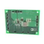
DEMO BOARD
Figure 1.
PLEASE SEE THE LAST PAGE FOR AN IMPORTANT
WARNING AND LEGAL TERMS AND CONDITIONS.
Rev. 0 | Page 1 of 12
�UG-504
Evaluation Board User Guide
TABLE OF CONTENTS
Features .............................................................................................. 1
Evaluation Board Schematics and Artwork ...................................5
General Description ......................................................................... 1
ADP2380 Schematic ......................................................................5
Demo Board ...................................................................................... 1
ADP2381 Schematic ......................................................................6
Revision History ............................................................................... 2
PCB Layout ....................................................................................7
Using the Evaluation Board............................................................. 3
Ordering Information .......................................................................8
Powering Up .................................................................................. 3
Bill of Materials ..............................................................................8
Measuring Evaluation Board Performance .................................. 3
Modifying the Board .................................................................... 4
REVISION HISTORY
12/12—Revision 0: Initial Version
Rev. 0 | Page 2 of 12
�Evaluation Board User Guide
UG-504
USING THE EVALUATION BOARD
POWERING UP
MEASURING EVALUATION BOARD PERFORMANCE
The ADP2380/ADP2381 evaluation board is supplied fully
assembled and tested. Before applying power to the evaluation
board, follow the procedures in this section.
Measuring the Switching Waveform
To observe the switching waveform with an oscilloscope, place the
oscilloscope probe tip at Test Point J4 (SW) with the probe ground
at J16 (GND). Set the scope to dc with the appropriate voltage and
time divisions. The switching waveform limits should alternate
approximately between 0 V and the input voltage.
Jumper J12 (EN/SS)
Use one of the following methods to enable or disable the
regulator:
•
•
Measuring Load Regulation
To enable the regulator, leave Jumper J12 open.
To disable the regulator, short Jumper J12.
Load regulation can be tested by observing the change in the
output voltage with increasing output load current. To minimize
the voltage drop, use short, low resistance wires.
Input Power Source
If the input power source includes a current meter, use that meter
to monitor the input current. Connect the positive terminal of
the power source to J5 (VIN) of the evaluation board, and the
negative terminal of the power source to J14 (GND) of the
evaluation board.
Measuring Line Regulation
If the power source does not include a current meter, connect a
current meter in series with the input source voltage. Connect the
positive lead (+) of the power source to the positive (+) ammeter
terminal, the negative lead (−) of the power source to J14
(GND), and the negative lead (−) of the ammeter to J5 (VIN).
Generate a step input voltage change and observe the behavior
of the output voltage using an oscilloscope.
Output Load
Before connecting the load, ensure that the board is turned off.
Connect an electronic load or resistor to set the load current.
Connect the positive terminal of the load to J6 (VOUT) of the
evaluation board and connect the negative terminal of the load to
J13 (GND).
Vary the input voltage and examine the change in the output
voltage with a fixed output current.
Line Transient Response
Load Transient Response
Generate a load current transient at the output and observe the
output voltage response using an oscilloscope. Attach the current
probe to the wire between the output and the load to capture
the current transient waveform.
Measuring Efficiency
The efficiency, η, is measured by comparing the input power with
the output power.
η=
Input and Output Voltmeter
Measure the input and output voltages using voltmeters. Ensure
that the voltmeters are connected to the appropriate terminals of
the evaluation board and not to the load or power source. If the
voltmeters are not connected directly to the evaluation board, the
measured voltages are incorrect, due to the voltage drop across the
leads and/or connections between the evaluation board, the
power source, and/or the load.
To measure the input voltage, connect the positive terminal of the
voltmeter to J7 (VIN_SENSE) and the negative terminal to J11
(GND_SENSE). Likewise, to measure the output voltage, connect
the positive terminal of the voltmeter to J8 (VOUT_SENSE) and
the negative terminal to J10 (GND_SENSE).
Turning On the Evaluation Board
Measure the input and output voltages as close as possible to the
input and output capacitors to reduce the effect of voltage drop.
Measuring Inductor Current
The inductor current can be measured by removing one end of
the inductor from its pad and connecting a current loop in series.
A current probe can be connected onto this wire.
Measuring Output Voltage Ripple
To observe the output voltage ripple, place the oscilloscope probe
across the output capacitor with the probe ground lead connected
to the negative (−) capacitor terminal and the probe tip placed at
the positive (+) capacitor terminal. Set the oscilloscope to ac,
10 mV/division, 2 µs/division time base, and 20 MHz bandwidth.
When the power source and load are connected to the evaluation
board, it can be powered for operation.
Perform the following steps to turn on the board:
1.
2.
3.
VOUT × I OUT
V IN × I IN
Ensure that the power source voltage is >4.5 V and
很抱歉,暂时无法提供与“ADP2380-EVALZ”相匹配的价格&库存,您可以联系我们找货
免费人工找货