ADP2441-EVALZ User Guide
UG-407
One Technology Way • P.O. Box 9106 • Norwood, MA 02062-9106, U.S.A. • Tel: 781.329.4700 • Fax: 781.461.3113 • www.analog.com
ADP2441 Evaluation Board
FEATURES
GENERAL DESCRIPTION
Full-featured evaluation board for the ADP2441
Configurable synchronous step down dc-dc switching
regulator
Operating voltage range of board: VIN = 6 V to 36 V
Output voltage is set to 5 V or can be adjusted
Maximum load 1 A
Switching frequency set to 500 kHz or adjustable switching
frequency of 300 kHz to 1 MHz
Power saving mode at light load
Precision enable input pin
Current limit protection
Power good output
External soft start set to 6 ms or external tracking available
Board size: 53 mm × 53 mm
The ADP2441 evaluation board is a complete, dc-to-dc switching regulator design based on the ADP2441, a configurable, 1 A,
synchronous step-down, dc-to-dc regulator.
The ADP2441 is a synchronous, step-down dc-to-dc switching
regulator that uses a current mode pulse-width modulation
(PWM) control scheme at medium-to-heavy load currents for
high efficiency and smoothly transitions to a pulse skip mode
at light loads to conserve power. The power switch and
synchronous rectifier are integrated for minimal external part
count and high efficiency. The ADP2441 is optimized for
operation with small ferrite core inductors and ceramic
capacitors to deliver the maximum output power per square
millimeter of the PCB board area.
The ADP2441-EVALZ is available with 5 V at 1 A output,
switching frequency set to 500 kHz. If needed, the ADP2441
evaluation board configuration can be modified by changing
the values of the appropriate passive components.
DOCUMENTS NEEDED
ADP2441 data sheet
UG-407
Complete specifications for the ADP2441 device can be found
in the ADP2441 data sheet, which is available from Analog
Devices, Inc., and should be consulted in conjunction with this
user guide when using the evaluation board.
10694-101
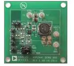
ADP2441-EVALZ
Figure 1.
PLEASE SEE THE LAST PAGE FOR AN IMPORTANT
WARNING AND LEGAL TERMS AND CONDITIONS.
Rev. 0 | Page 1 of 12
�UG-407
ADP2441-EVALZ User Guide
TABLE OF CONTENTS
Features .............................................................................................. 1
Modifying the Evaluation Board .....................................................5
Documents Needed .......................................................................... 1
Changing the Output Voltage ......................................................5
General Description ......................................................................... 1
Changing the Switching Frequency ............................................5
ADP2441-EVALZ ............................................................................. 1
Changing the Soft Start Time ......................................................5
Revision History ............................................................................... 2
Typical Performance Characteristics ..............................................6
Using the Evaluation Board............................................................. 3
Evaluation Board Schematics and Artwork ...................................8
Powering Up the Evaluation Board ............................................ 3
Ordering Information .................................................................... 10
Measuring Evaluation Board Performance ............................... 4
Bill of Materials ........................................................................... 10
REVISION HISTORY
6/12—Initial Version: Revision 0
Rev. 0 | Page 2 of 12
�ADP2441-EVALZ User Guide
UG-407
USING THE EVALUATION BOARD
PGOOD Signals
POWERING UP THE EVALUATION BOARD
When the output is enabled and the output voltage, VOUT, is in
regulation, the logic signal at the PGOOD test point is high. In
a typical application, a pull-up resistor from the PGOOD pin to
the external supply is used to generate this logic signal.
Input Power Source
The power source voltage must not exceed 36 V, the maximum
operation input voltage of the ADP2441.
Make sure the power source is switched off before connecting it
to the ADP2441 evaluation board. Connect the positive
terminal of the power source to the evaluation board VIN
terminal (T1), and the negative terminal of the power source to
the evaluation board GND terminal (T2). If the power source
includes an ammeter, connect the ammeter in series with the
input source voltage. Connect the positive lead (+) of the power
source to the ammeter positive (+) connection, the negative
lead (−) of the ammeter to the evaluation board VIN terminal
(T1), and the negative lead (−) of the power source to the
evaluation board GND terminal (T2).
Output Load
Make sure the evaluation board is switched off before connecting the load. Connect the load directly to the evaluation board,
with the positive (+) load connection to the VOUT terminal
(T3) and the negative (−) load connection to the GND terminal
(T4). If an ammeter is used, connect it in series with the load:
connect the positive (+) ammeter terminal to the evaluation
board VOUT terminal (T3), the negative (−) ammeter terminal
to the positive (+) load terminal, and the negative (−) load
terminal to the evaluation board GND terminal (T4).
On the evaluation board, the pull-up resistor (R7) is available to
connect to the external supply through the jumper (JP1). Test
Point TP2 is available to connect the external supply of 5 V.
PGOOD
R7
50kΩ
JP1
10694-001
The ADP2441 evaluation board is provided fully assembled
and tested. Before applying power to the evaluation board,
follow the procedures in this section.
TP2: EXTERNAL
SUPPLY: 5V
Figure 2 PGOOD Signal
External SS/Track Signal
The SS/TRK pin is multipurpose. It can be used either for
tracking the external supply or for soft start.
A header, TRK, is available on the board for connecting an
external signal to be tracked by the regulator output voltage.
Before applying a signal to the TRK header, make sure the
voltage divider resistor values (R10, R11) connected on the
evaluation board are the correct values (see the ADP2441
data sheet).
Alternatively, to program soft start time, a capacitor can be
connected to SS/TRK pin. On the evaluation board, a 10 nF
capacitor, C11, is connected for a soft start time of 6 ms.
Once the load is connected, make sure it is set to the proper
current before powering the ADP2441 evaluation board. Before
connecting a load to the output of the evaluation board, make
sure that the output voltage does not exceed the maximum
operating voltage range of the load.
SS
SS/TRK
C11
10nF
TRK
Enabling and Disabling the DC-to-DC Switching
Regulator
R11
OPEN
In the evaluation board, a voltage divider is used to generate
an enable signal for the IC. As soon as voltage is applied to
VIN (24 V), IC is enabled.
10694-002
R10
OPEN
Figure 3. Soft Start Signal
Alternatively, header TP1 (EN) is available to enable and disable
the evaluation board. To enable the output, connect the header
TP1 to the VIN supply or to an external voltage source. To disable
the output connect the header TP1 to the GND.
Rev. 0 | Page 3 of 12
�UG-407
ADP2441-EVALZ User Guide
Measuring Line Regulation
MEASURING EVALUATION BOARD
PERFORMANCE
Output Voltage Ripple
To observe the output voltage ripple, place an oscilloscope
probe tip at Terminal T3 and connect the probe ground lead at
the negative (−) Terminal T4. Set the oscilloscope to an accoupled, 100 mV/division and 2 μs/division time base.
Switching Waveform
To observe the switching waveform with an oscilloscope, place
the oscilloscope probe tip at the end of the inductor that is
connected to the SW pin with the probe ground at Terminal T4,
GND. Set the scope to dc, 5 V/division, and 2 µs/division time
base. The switching waveform should alternate between 0 V
and approximately the input voltage.
Vary the input voltage and examine the change in the output
voltage. In PWM mode, the output voltage ripple should be
small (