HMC424ALH5
v00.0416
ATTENUATORS - DIGITAL - SMT
0.5dB LSB GaAs MMIC 6-BIT DIGITAL
ATTENUATOR, DC - 13 GHz
Typical Applications
Features
The HMC424ALH5 is ideal for:
0.5 dB LSB Steps to 31.5 dB
• Telecom Infrastructure
Single Control Line Per Bit
• Military Radio, Radar & ECM
± 0.3 dB Typical Bit Error
• Space Systems
Hermetic SMT Package, 25mm2
Screening to MIL-PRF-38535 (Class B or S) Available
• Test Instrumentation
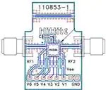
Functional Diagram
General Description
The HMC424ALH5 is a broadband 6-bit GaAs MMIC
digital attenuator housed in a hermetic SMT leadless
package. Covering DC to 13 GHz, the insertion loss is
less than 3.5 dB typical. The attenuator bit values are
0.5 (LSB), 1, 2, 4, 8, and 16 dB for a total attenuation
of 31.5 dB. Attenuation accuracy is excellent at ±0.5
dB typical step error with an IIP3 of +34 dBm. Six
control voltage inputs, toggled between 0 and -5V,
are used to select each attenuation state. A single
Vee bias of -5V allows operation at frequencies down
to DC. The HMC424ALH5 is compatible with standard and lead free surface mount manufacturing
techniques and is suitable for high reliability military,
industrial and space applications.
Electrical Specifications, TA = +25° C, With Vee = -5V & VCTL= 0/-5V
Parameter
Frequency (GHz)
Typ.
Max.
Units
DC - 4 GHz
4.0 - 8.0 GHz
8.0 - 12.0 GHz
12.0GHz - 13.0 GHz
2.7
3.3
4.2
4.7
3.2
3.8
4.7
5.2
dB
dB
dB
Attenuation Range
DC - 13.0 GHz
31.5
dB
Return Loss (RF1 & RF2, All Atten. States)
DC - 13.0 GHz
12
dB
DC - 13.0 GHz
DC - 13.0 GHz
± 0.4 + 4% of Atten. Setting Max
± 0.5 + 5% of Atten. Setting Max
dB
dB
1.0 - 13.0 GHz
27
dBm
1.0 - 13.0 GHz
40
34
dBm
dBm
30
55
ns
ns
Insertion Loss
Min.
Attenuation Accuracy: (Referenced to Insertion Loss)
0.5 - 16.5 dB States
17 - 31.5 dB States
Input Power for 0.1 dB Compression
Input Third Order Intercept Point
(Two-Tone Input Power= 0 dBm Each Tone)
REF State
All Other States
Switching Characteristics
tRISE, tFALL (10/90% RF)
tON/tOFF (50% CTL to 10/90% RF)
1
Information furnished by Analog Devices is believed to be accurate and reliable. However, no
responsibility is assumed by Analog Devices for its use, nor for any infringements of patents or other
rights of third parties that may result from its use. Specifications subject to change without notice. No
license is granted by implication or otherwise under any patent or patent rights of Analog Devices.
Trademarks and registered trademarks are the property of their respective owners.
DC - 13.0 GHz
For price, delivery, and to place orders: Analog Devices, Inc.,
One Technology Way, P.O. Box 9106, Norwood, MA 02062-9106
Phone: 781-329-4700 • Order online at www.analog.com
Application Support: Phone: 1-800-ANALOG-D
�HMC424ALH5
v00.0416
0.5dB LSB GaAs MMIC 6-BIT DIGITAL
ATTENUATOR, DC - 13 GHz
Return Loss RF1, RF2
Insertion Loss
(Only Major States are Shown)
0
-5
RETURN LOSS (dB)
INSERTION LOSS (dB)
-2
-4
-6
-10
-15
-20
-8
-25
-10
0
0
3
6
9
12
3
6
15
9
12
15
FREQUENCY (GHz)
FREQUENCY (GHz)
+25 C
+85 C
I.L.
0.5 dB
1 dB
-40 C
Normalized Attenuation
2
0
-5
1
BIT ERROR (dB)
-10
-15
-20
-25
0
-1
-30
-2
-35
0
1
2
3
4
5
6
7
8
9
0
10 11 12 13 14 15
4
8
IL
0.5 dB
1 dB
12
16
20
24
28
32
ATTENUATION STATE (dB)
FREQUENCY (GHz)
2 dB
4 dB
8 dB
0.1 GHz
4 GHz
16 dB
31.5 dB
Bit Error vs. Frequency
8 GHz
13 GHz
Relative Phase vs. Frequency
(Only Major States are Shown)
(Only Major States are Shown)
80
RELATIVE PHASE (deg)
2
1
BIT ERROR (dB)
16 dB
31.5 dB
Bit Error vs. Attenuation State
(Only Major States are Shown)
NORMALIZED ATTENUATION (dB)
2 dB
4 dB
8 dB
ATTENUATORS - DIGITAL - SMT
0
0
-1
60
40
20
0
-20
0
3
-2
0
3
6
9
12
0.5 dB
1 dB
2 dB
FREQUENCY (GHz)
0.5 dB
1 dB
2 dB
4 dB
8 dB
16 dB
6
9
12
15
FREQUENCY (GHz)
15
4 dB
8 dB
16 dB
31.5 dB
31.5 dB
For price, delivery, and to place orders: Analog Devices, Inc., One Technology Way, P.O. Box 9106, Norwood, MA 02062-9106
Phone: 781-329-4700 • Order online at www.analog.com
Application Support: Phone: 1-800-ANALOG-D
2
�HMC424ALH5
v00.0416
0.5dB LSB GaAs MMIC 6-BIT DIGITAL
ATTENUATOR, DC - 13 GHz
Step Error vs. Frequency (Major States)
Bias Voltage & Current
Vee Range= -5 Vdc ± 10%
1.5
STEP ERROR (dB)
ATTENUATORS - DIGITAL - SMT
2
1
0.5
Vee
(VDC)
Iee (Typ.)
(mA)
Iee (Max.)
(mA)
-3.0
2.2
5
-5.0
2.3
5
0
-0.5
-1
-1.5
-2
0
1
2
3
4
5
6
7
8
9
10 11 12 13 14 15
FREQUENCY (GHz)
IL
0.5 dB
1 dB
2 dB
4 dB
8 dB
16 dB
31.5 dB
Truth Table
Control Voltage Input
Control Voltage
State
Bias Condition
Low
0 to -3V @ 35 µA Typ.
High
Vee to Vee +0.8V @
很抱歉,暂时无法提供与“EV1HMC424ALH5”相匹配的价格&库存,您可以联系我们找货
免费人工找货