Engineer-to-Engineer Note
EE-419
Technical notes on using Analog Devices A2B® products and development tools
Visit
our
Web
resources
http://www.analog.com/ee-notes
and
http://www.analog.com/a2b.
EVAL-AD2428WB1BZ A²B Evaluation Board User Guide
Contributed by A2B Applications Team
Rev 1 – October 8, 2019
Features
Bus-Powered
(AD2428W)
A2B®
Slave
Stereo
Audio
(ADAU1761)
Analog Line-Level Audio
example, a Smartphone)
EVAL-AD2428WD1BZ A2B Master Node
Evaluation Board
Additional A2B Slave Nodes (Optional)
Transceiver
Codec/SigmaDSP®
Two Stereo MEMS Microphones
EVAL-AD2428WG1BZ
EEPROM
EVAL-AD2428WC1BZ
LED and Push-Button on GPIO/IRQ
Test Points for Digital Signals and Analog
Inputs
Included Equipment
1.8 m Twisted-Pair Cable (CAT5e-Rated,
with DuraClikTM Connectors)
Rubber Feet
Equipment Needed
Headphone with Cable and 3.5 mm TRS Plug
Source
(for
Documents Needed
Transceiver Data Sheet[1]
Transceiver Technical Reference[2]
EVAL-AD2428WB1BZ Hardware Design
Files[3]
Software Needed
SigmaStudio® Rev. 4.4 or later
Software Distribution for A2B Rev 19.3.0 or
later, DLLs
Copyright 2019, Analog Devices, Inc. All rights reserved. Analog Devices assumes no responsibility for customer product design or the use or application of customers’
products or for any infringements of patents or rights of others which may result from Analog Devices assistance. All trademarks and logos are property of their
respective holders. Information furnished by Analog Devices applications and development tools engineers is believed to be accurate and reliable, however no
responsibility is assumed by Analog Devices regarding technical accuracy and topicality of the content provided in Analog Devices Engineer-to-Engineer Notes.
�General Description
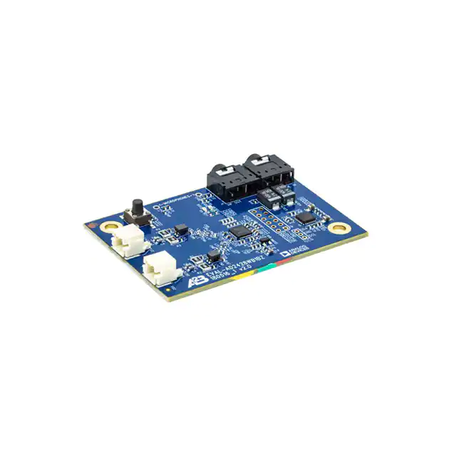
This evaluation board provides A2B bus-powered slave node functionality for an A2B network, including
support for both PDM microphone input and serial audio via an I2S/TDM interface. Bus-powered slave
nodes derive power from the bias voltage on the A2B wires.
An audio codec/SigmaDSP (ADAU1761) with stereo analog ADC input and two digital MEMS
microphones with PDM output can feed the upstream or downstream slots on the A2B bus while the DAC
outputs of the codec/SigmaDSP may use or consume upstream or downstream slots on the A2B bus. The
SigmaDSP block allows optional digital pre- or post-processing.
A pushbutton and LED are available for interactive control and response communication over the A2B bus.
The standard 0.1 inch (2.54mm) pin distance, dual-row header (unpopulated) provides direct connectivity
to I2S/TDM and ground signals for testing or interfacing to other devices after discovery. All power supplies
are easily accessible at surface-mount test points located on the bottom of the board. For the board
schematics, assembly/layout files, and bill of materials (BOM), see the EVAL-AD2428WB1BZ Hardware
Design Files ZIP archive associated with this EE-note[3].
Evaluation Board Hardware
Figure 1 identifies the important components and connection points on the EVAL-AD2428WB1BZ
evaluation board.
Figure 1. Board Overview
EVAL-AD2428WB1BZ A²B Evaluation Board User Guide (EE-419)
Page 2 of 10
�A2B Bus Connections (J7 and J8)
The 2-pin Molex DuraClik connector (J7) allows a single twisted-pair A2B cable to attach to the A-side of
the AD2428W transceiver. The opposite end of the A2B cable can attach to the B-side of either the master
transceiver or the next slave node transceiver closer to the master node.
The 2-pin Molex DuraClik connector (J8) allows a single twisted-pair A2B cable to attach to the B-side of
the AD2428W transceiver. The opposite end of the A2B cable can attach to the A-side of the next slave
node transceiver, including the last-in-line slave.
I2C Header (J3)
The unpopulated I2C header (J3) footprint provides access to the I2C interface of the A2B transceiver (SDA,
SCL, and GND signals).
Analog Audio Input (J2) and Output (J1) Signals
The EVAL-AD2428WB1BZ evaluation board provides two 3.5mm TRS connectors for stereo, single-ended
signals that conform to audio line-levels.
An MP3 player (for example, an iPOD®) or smartphone audio output can directly feed the AC-coupled input
(J2) to the ADC of the ADAU1761 SigmaDSP. Non-audio signals with a peak-to-peak swing of less than
2.8V are also supported.
The DAC outputs from the ADAU1761 SigmaDSP can be used to send an analog signal to an external
device (J1), with the primary function being driving headphones.
When nothing is plugged into the J1 and J2 jacks, the analog audio output routes to the analog audio input
of the ADAU1761 SigmaDSP through switched contacts inside the connectors. This design facilitates
analog loop back testing.
Because of the bus bias voltage functionality, the ground of a bus-powered node
is not at the same potential as the ground of a locally-powered node. This
difference can cause discovery errors if the signal source or destination ground
that is connected to the bus-powered node is at the same potential as a locallypowered node in the system. For this reason, only floating signals (such as
battery-powered MP3 players and headphones) should be connected to the
EVAL-AD2428WB1BZ board.
Microphones
There are two digital MEMS microphones connected directly to the transceiver through PDM.
I2S/TDM Header (J4)
The unpopulated dual-row J4 footprint provides access to the I2S/TDM interface of the A2B transceiver
(BCLK, SYNC, DTX0, DTX1, DRX0, and DRX1 signals). It allows connection to other PCBs (either
directly or through wires) and permits monitoring of the signals using either a logic analyzer or a digital
audio analyzer. One side of the header is connected to ground for improved signal integrity when using
shielded or twisted-wire connections.
EVAL-AD2428WB1BZ A²B Evaluation Board User Guide (EE-419)
Page 3 of 10
�LEDs (D8 and D9)
D8 and D9 reflect the status of the AD2428W IRQ/IO0 and DTX1/IO4 pins, respectively, when used as
GPIO.
Test Points (TP7 – TP12)
The test points are well-marked on the silkscreen of the PCB, providing access to signals and power
supplies, as summarized in Table 1. Refer to the schematics to locate the probe points.
Test Point
Provides Access To (A2B Transceiver Pin, If Applicable)
TP7
AD2428W VOUT1 Output Voltage (PLLVDD/DVDD)
TP8
AD2428W VOUT2 Output Voltage (ATRXVDD/BTRXVDD)
TP9
VBUS Low - Negative Bus Bias Recovered on this Node
TP10
VBUS High - Positive Bus Bias Recovered on this Node
TP11
AD2428W Next Slave Power Sense (SENSE)
TP12
AD2428W Return Current for Next Slave (VSSN)
Table 1. EVAL-AD2428WB1BZ Evaluation Board LED Summary
ADAU1761 SigmaDSP
The non-automotive-qualified ADAU1761 SigmaDSP is functionally equivalent to the obsolete
automotive-qualified ADAU1461. This device is also pin-compatible with the automotive-qualified
ADAU1361 and ADAU1961 products, which do not include a SigmaDSP processor core for digital audio
pre- and post- processing.
Pushbutton (S1)
The AD2428W IRQ/IO0 pin is pulled high to IOVDD such that depressing the pushbutton (S1) can generate
an active-low interrupt to the AD2428W transceiver. Configure the IRQ/IO0 pin as an active low GPIO
with interrupt capabilities to use this feature.
EEPROM
The default EEPROM content for this board is described in Table 2:
Address
Data
Content
0x0000
0xAB
Configuration Memory Indicator
0x0001
0xAD
Module Vendor ID
0x0002
0x28
Module Product ID
0x0003
0xD2
Module Version ID
0x0004
0x12
RESERVED (Ignore)
0x0005
0x00
Number of Configuration Blocks
Table 2. EEPROM Settings for AD2428W Transceiver
EVAL-AD2428WB1BZ A²B Evaluation Board User Guide (EE-419)
Page 4 of 10
�I2C Device Addresses in 7-bit Format
The I2C device address in 7-bit format does not include the read-write (R/W) bit. The schematics tab in the
SigmaStudio A2B window uses the 7-bit address representation for configuration, as summarized in Table 3.
Both devices are 16-bit addressable and utilize 8-bit data.
Device
7-Bit I2C Device Address
ADAU1761 SigmaDSP with Codec
0x39
24FC256 EEPROM
0x50
Table 3. 7-Bit I2C Device Addresses
Evaluation Board Software Quick Start Procedure
The EVAL-AD2428WB1BZ evaluation board is intended to be connected within an existing A2B system,
where at least a master node exists for the on-board AD2428W transceiver to be a slave to on the A2B bus.
A host processor on the master node interfaces directly with the A2B master transceiver through which it
programs and reads the register spaces of all discovered slave transceivers. This configuration allows a full
system initialization at start-up and status monitoring during operation.
The examples furnished with the complementary EVAL-AD2428WD1BZ A2B master evaluation board
assume a connection to specific slave boards, as noted in the following sections.
Connection to EVAL-AD2428WD1BZ Master Board
For master board setup instructions, refer to the EVAL-AD2428WD1BZ A2B Evaluation Board Manual[4].
Ensure that the master board jumpers are installed in their default positions.
Hardware Setup for a 3-Node A2B System
1. Assemble the example A2B system by connecting the indicated A2B evaluation boards as follows:
Master (EVAL-AD2428WD1BZ) – Connect the B-side (P2) to the A-side on the slave0 board (J7).
Slave0 (EVAL-AD2428WC1BZ) – Connect the B-side (J8) to the A-side on the slave1 board (J7).
Slave1 (EVAL-AD2428WB1BZ)
2. Connect the PC over a USB cable and using the EVAL-ADUSB2EBZ USBi I2C programmer to the
SigmaStudio header (P1) on the master board.
3. Connect an audio source to the stereo line input of the slave1 board (J2).
4. Connect headphones to the audio output of the master board (J4).
5. Plug the wall-mount 12V power supply (1.5 A) into an outlet and connect it to the power jack on the
master board (P4).
Software Setup and Operation
1. Install the SigmaStudio (Rev. 4.4 or later) and A2B Software for Windows/Baremetal (Rev 19.3.0)
software from the EVAL-AD2428WB1BZ product page.
2. Copy the A2B.dll and A2Bstack.dll driver files from the installation directory (default C:\Analog
Devices\ADI_A2B_Software-Rel19.3.0\GUI\x86_x64) into the SigmaStudio installation (default
EVAL-AD2428WB1BZ A²B Evaluation Board User Guide (EE-419)
Page 5 of 10
�C:\Program Files\Analog Devices\SigmaStudio 4.4). Start SigmaStudio
A2B.dll file is selected under ToolsAddInsBrowser. Save before exiting.
and verify that the
3. Open the adi_a2b_3NodeSampleDemo.dspproj example project, which is located in the (default)
C:\Analog Devices\ADI_A2B_Software-Rel19.3.0\Schematics\BF\A2BSchematics directory.
Click the Link-Compile-Download icon, as shown in Figure 2.
Figure 2. Software Schematic for adi_a2b_3NodeSampleDemoConfig.dspproj A2B Example Project
4. Before running the demo, follow the Hardware Setup for a 3-Node A2B System guidance. The sample
demo configuration appears as shown in Figure 2. The audio source connected to the slave1 EVALAD2428WB1BZ board plays out of the headphones connected to the master EVAL-AD2428WD1BZ
board. The microphone audio from the slave0 EVAL-AD2428WC1BZ board plays out of the slave1
EVAL-AD2428WB1BZ board.
5. Use the configuration settings shown in Figure 3 to properly interface the codec with the A2B
transceiver.
EVAL-AD2428WB1BZ A²B Evaluation Board User Guide (EE-419)
Page 6 of 10
�Figure 3. EVAL-AD2428WB1BZ Evaluation Board Example Audio Configuration
Figure 4 shows an example of a downstream data configuration where two slots are consumed from the
A2B bus and sent to the local DAC while two additional slots are contributed by the transceiver taking
data from the local ADC.
EVAL-AD2428WB1BZ A²B Evaluation Board User Guide (EE-419)
Page 7 of 10
�Figure 4. EVAL-AD2428WB1BZ Evaluation Board Example Slot Assignments
6. The ADAU1452 SigmaDSP on the master EVAL-AD2428WD1BZ board supplies the clock (SYNC)
to the AD2428W transceiver. For development of customized ADAU1452 audio flows, disable the
automatic programming of the ADAU1452 during discovery. Right-click the ADAU1452 block and
select Peripheral Properties in the A2B software schematics.
7. To test the PDM microphones on the slave1 EVAL-AD2428WB1BZ board, make the connections
shown in Figure 2. Click on RX1 in the A2B cell to change the input to PDM, as shown in Figure 5.
Figure 5. Changing AD2428W Pin Function from DRX1 to PDM1
The headphones connected to the master EVAL-AD2428WD1BZ board can be used to listen to the
microphone data coming from the slave1 EVAL-AD2428WB1BZ board.
8. Use the Stream Config tab (right-click on Target Processor Device Properties Stream Config) to
define audio streams across the nodes (Figure 6). The stream assignments configure the upstream and
downstream slot settings across the nodes.
EVAL-AD2428WB1BZ A²B Evaluation Board User Guide (EE-419)
Page 8 of 10
�Figure 6: Stream Configuration
Refer to the Quick Start Guide[5] from the A2B software distribution for guidance regarding the modification
of the software.
EVAL-AD2428WB1BZ A²B Evaluation Board User Guide (EE-419)
Page 9 of 10
�References
[1] AD2820(W)/AD2426(W)/AD2427(W)/AD2428(W)/AD2429(W) Automotive Audio Bus A2B Transceiver Data Sheet. Rev
A, October 2019. Analog Devices, Inc.
[2] AD2420(W)/6(W)/7(W)/8(W)/9(W) Automotive Audio Bus A2B Transceiver Technical Reference. Rev 1.1, October 2019.
Analog Devices, Inc.
[3] Associated ZIP File (EE419v01.zip) for EVAL-AD2428WB1BZ A2B Evaluation Board User Guide (EE-419). October
2019. Analog Devices, Inc.
[4] EVAL-AD2428WD1BZ A2B Evaluation Board Manual. Rev 1.1, October 2019. Analog Devices, Inc.
[5] A2B Quick Start Guide. Revision 25.0, October 2019. Analog Devices, Inc.
Document History
Revision
Description
Rev 1 – October 17, 2019
by A2B Applications Team
Initial Release
EVAL-AD2428WB1BZ A²B Evaluation Board User Guide (EE-419)
Page 10 of 10
�