EVAL-ADM1075MEBZ User Guide
UG-548
One Technology Way • P.O. Box 9106 • Norwood, MA 02062-9106, U.S.A. • Tel: 781.329.4700 • Fax: 781.461.3113 • www.analog.com
ADM1075 Mini Evaluation Kit User Guide
FEATURES
GENERAL DESCRIPTION
Mini evaluation kit for the ADM1075
Supports LFCSP device package
Input voltage range of −30 V to −75 V
PMBus™ communication supported
Isolated PMBus interface for −48 V operation
Special N-MOSFET footprint to accommodate different
FET packages
Supports up to 2 sense resistors in parallel
Supports up to 2 field effect transistors (FETs) in parallel
Toggle and push-button switches for easy input control
LED indicated status outputs
Smaller board compared with EVAL-ADM1075EBZ
The ADM1075 mini evaluation board (EVAL-ADM1075MEBZ) is
a compact, reduced feature version of the ADM1075 evaluation
board (EVAL-ADM1075EBZ) for the ADM1075-1ACPZ and
ADM1075-2ACPZ devices.
The mini evaluation board is designed to power up with a 15 A
current limit, a 300 μF load capacitance, and a minimum of 24 Ω
load resistance.
Two sense resistor footprints and two FET footprints provide
users with flexibility and allow them to simulate a wide range of
application setups.
Multiple test points allow easy access to all critical points and
pins. There is one LED to provide users with a direct visual
indication of IC power good output.
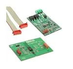
EVALUATION KIT CONTENTS
EVAL-ADM1075MEBZ mini evaluation board
EVAL-ADM1075-ISOZ isolation board
8-way, 150 mm Micro-MaTch ribbon cable
The EVAL-ADM1075MEBZ board is fully compatible with the
EVAL-ADM1075EBZ evaluation software tool, which can be
downloaded from www.analog.com/hotswaptools.
ADDITIONAL EQUIPMENT NEEDED
Users need a USB-SDP-CABLEZ USB-to-I2C dongle to use the
evaluation software tools. The Micro-MaTch ribbon cable is
required if connecting the mini evaluation board to the isolation
board (EVAL-ADM1075-ISOZ).
USB-to-serial I/O interface USB-SDP-CABLEZ
REQUIRED SOFTWARE
Analog Devices hot swap and power monitoring evaluation
software (download from www.analog.com/hotswaptools)
Complete specifications for the ADM1075 can be found in the
ADM1075 data sheet, available at http://www.analog.com/, and
should be consulted in conjunction with this user guide when
using the evaluation board.
BOARD SETUP
RTNIN
EVAL-ADM1075MEBZ
–48VIN
–48VOUT
EVAL-ADM1075-ISOZ
Figure 1.
PLEASE SEE THE LAST PAGE FOR AN IMPORTANT
WARNING AND LEGAL TERMS AND CONDITIONS.
Rev. A | Page 1 of 16
11414-001
TO PC
�UG-548
EVAL-ADM1075MEBZ User Guide
TABLE OF CONTENTS
Features .............................................................................................. 1
EVAL-ADM1075-ISOZ ................................................................6
Evaluation Kit Contents ................................................................... 1
Evaluation Board Hardware .............................................................7
Additional Equipment Needed ....................................................... 1
Switch, Jumper, and LED Functions ...........................................7
Required Software ............................................................................ 1
Test Plots .............................................................................................9
General Description ......................................................................... 1
Evaluation Board Schematics and Layout ................................... 10
Board Setup ....................................................................................... 1
EVAL-ADM1075MEBZ ............................................................ 10
Revision History ............................................................................... 2
EVAL-ADM1075-ISOZ ............................................................. 12
Quick Start Guide ............................................................................. 3
Bill of Materials ............................................................................... 15
Evaluation Board Description......................................................... 4
EVAL-ADM1075MEBZ ............................................................ 15
EVAL-ADM1075MEBZ .............................................................. 5
EVAL-ADM1075-ISOZ ............................................................. 16
REVISION HISTORY
4/14—Rev. 0 to Rev. A
Changes to Evaluation Kit Contents .............................................. 1
Changes to Figure 11 ...................................................................... 10
Changes to Table 11 ........................................................................ 15
4/13—Revision 0: Initial Version
Rev. A | Page 2 of 16
�EVAL-ADM1075MEBZ User Guide
UG-548
QUICK START GUIDE
1.
2.
3.
4.
5.
6.
Download the hot swap and power monitor software from
www.analog.com/hotswaptools (see the UG-353 user guide
for more information).
Connect the mini evaluation board (EVAL-ADM1075MEBZ)
to the isolation board (EVAL-ADM1075-ISOZ) using the
8-way connector and a Micro-MaTch ribbon cable.
Connect the isolation board (EVAL-ADM1075-ISOZ) to a PC
through the 10-way connector and the USB-SDP-CABLEZ
dongle. The blue LED, labeled ISO, on the isolation board
illuminates.
Connect the power supply to the mini evaluation board
(EVAL-ADM1075MEBZ) using thick wires.
To confirm that the boards are configured correctly, set the
output of the power supply to 48 V with less than a 1 A
current limit and with no load capacitance. If the boards
are configured correctly, the green LEDs, labeled
D_PWRGD on the EVAL-ADM1075MEBZ and PWRGD
on the EVAL-ADM1075-ISOZ, illuminate.
Press the RESTART push-button on the mini evaluation
board (EVAL-ADM1075MEBZ). The green LEDs, labeled
D_PWRGD and PWRGD, both turn off, and then turn
back on after 10 sec.
7.
You can use the SHDN2 switch and SHDN push-button on
the isolation board (EVAL-ADM1075-ISOZ) to turn off
the hot swap.
8. If a latch event occurs (for example, a short circuit during
operation), the red LED, labeled LATCH, illuminates on
the isolation board (EVAL-ADM1075-ISOZ). The latch
event can be cleared with a CLEAR FAULT PMBus command
or by pressing the DELATCH push-button.
9. Disable the hot swap using the Hot Swap Control section
of the Basic Operation tab of the GUI. Disabling the hot
swap should turn off the green LEDs (D_PWRGD and
PWRGD) on both the mini evaluation board and the
isolation board.
10. Manually program the sense resistor value and the ADC
input resistor divider values (for example, RSENSE = 1.5 mΩ,
ADC top = 200 kΩ, ADC bottom = 2.8 kΩ). There is no
EEPROM available on the mini evaluation board (EVALADM1075MEBZ); therefore, these values must be
programmed each time the software GUI is opened.
11. Check that the voltage and current measurements are as
expected in the Power Monitor tab of the software GUI.
Rev. A | Page 3 of 16
�UG-548
EVAL-ADM1075MEBZ User Guide
EVALUATION BOARD DESCRIPTION
The mini evaluation board (EVAL-ADM1075MEBZ) is connected
to the isolation board (EVAL-ADM1075-ISOZ) using a MicroMaTch cable and is connected to a PC using a USB-SDP-CABLEZ
dongle for isolated I2C communication.
The EVAL-ADM1075MEBZ is designed to demonstrate several
features of the ADM1075. It is used in conjunction with the
isolation board to provide a fully isolated solution. A simplified
drawing of the mini evaluation board and isolation board
combination is shown in Figure 2.
RTNIN
–48VIN
RV
PWRGD
CLOAD
–48VOUT
VIN
ADM1075
R1
D1
RESTART
UVL
GATE
R2
N-FET
SENSEN SENSEP
I2C
RSENS
DIGITAL
ADM1075-MEBZ
SHDN2
PWRGD
DELATCH SHDN SPARE
5V
5V_ ISO
LATCH_ISO
LATCH
GPO2
ADuM5404
PWRGD
PWRGD_ISO
UL_SPLYGD
SPLYGD_ISO
SDA
SCL
5V
ISO
SDA_ISO
ADuM1250
–48V
ADM1075-ISOZ
LATCH
GPO2_ISO
SCL_ISO
5V_ ISO
GND_ ISO
ISOLATION
BARRIER
Figure 2. Basic Block Diagram
Rev. A | Page 4 of 16
11414-002
RLOAD
�EVAL-ADM1075MEBZ User Guide
UG-548
EVAL-ADM1075MEBZ
The ADM1075 mini evaluation board (EVAL-ADM1075MEBZ)
is shown in Figure 3.
Thick wires should be used between the power supply and the
EVAL-ADM1075MEBZ board connector to minimize inductance.
The D_PWRGD LED illuminates green after the board is powered
and the ADM1075 GATE pin is high (FET fully enhanced).
Pressing the RESTART push-button triggers a shutdown that
lasts for 10 sec.
The EVAL-ADM1075MEBZ uses a 470 nF timer capacitor to
maintain a 10 ms FET safe operating area. The undervoltage
and overvoltage thresholds were set using resistor dividers to
achieve the values shown in Table 1. A resistor divider was also
used on the ISET pin to set the current limit to approximately
15 A. The constant power level was set to the maximum allowable
level for the FET safe operating area to allow power-up in one
attempt. These values can all be fine-tuned further if necessary.
Isolation is required in most −48 V applications because there is
a large ground potential difference between the −48 V section
of the board and a PC or microcontroller.
11414-003
The board is intended to be plugged into a system where load
capacitance already exists. Two through-hole vias are provided
to allow the placement of a load capacitor on the board when
testing the board outside of a real system. All testing performed
on the board was done with a 330 μF load capacitor.
Figure 3. EVAL-ADM1075MEBZ Board
Specifications
Table 1.
Parameter
Undervoltage Rising Threshold, VUVH
Undervoltage Falling Threshold, VUVL
Overvoltage Rising Threshold, VOVR
Overvoltage Falling Threshold, VOVF
Trip Current
Regulation Current
Constant Power Level
Min
−34.0
−30.6
−70.3
−68.9
12.1
12.9
127
Rev. A | Page 5 of 16
Typ
−35.0
−31.5
−72.4
−71.4
12.75
13.3
135
Max
−36.0
−32.4
−74.6
−74.0
13.4
13.8
142
Unit
V
V
V
V
A
A
W
�UG-548
EVAL-ADM1075MEBZ User Guide
EVAL-ADM1075-ISOZ
The ADM1075 isolation board (EVAL-ADM1075-ISOZ) includes
the following isolators:
The ADuM1250 is used to demonstrate the I2C isolation
and the digital signal.
The ADuM5404 provides quad-channel digital isolation
with isoPower®. When the isolated section is powered,
the isoPower device powers the 5 V components on the
primary side of the board.
11414-004
The push-buttons and switch on the isolation board (EVALADM1075-ISOZ) allow the user to control the mini evaluation
board (EVAL-ADM1075MEBZ). The three on-board LEDs
provide users with a direct visual indication of IC power good,
latch event occurrence, and 5 V power supply from USB-SDPCABLEZ. The 8-way connector is used to connect the mini
evaluation board (EVAL-ADM1075MEBZ) to the isolation board
(EVAL-ADM1075-ISOZ), and the 10-way connector is used
with the USB-SDP-CABLEZ dongle to connect the isolation
board (EVAL-ADM1075-ISOZ) to a PC.
Figure 4. EVAL-ADM1075-ISOZ Board
Rev. A | Page 6 of 16
�EVAL-ADM1075MEBZ User Guide
UG-548
EVALUATION BOARD HARDWARE
SWITCH, JUMPER, AND LED FUNCTIONS
EVAL-ADM1075MEBZ
Table 2. Connector Functions
Connector
RTNIN, −48VIN
−48VOUT
J3
Description
Hot swap line voltage inputs that also power the board components. The input voltage ranges from −30 V to −75 V.
Hot swap line voltage output.
8-way connector; use a Micro-MaTch ribbon cable to connect to an EVAL-ADM1075-ISOZ isolation board.
Table 3. Switch Functions
Switch
RESTART
Description
Push-button switch to trigger a shutdown that lasts for 10 sec.
Table 4. LED Functions
LED
D_PWRGD
Description
PWRGD, active low; green.
Table 5. On-Board ICs
IC
U1
Description
ADM1075 main IC.
Table 6. Retry Configuration
Retry Scheme
No Retries (Latch Off)
Seven Retries, Then Latch Off (Default)
One Retry Every 10 sec
Seven Retries Every 10 sec
R-7RTY
Not populated
0Ω
Not populated
Not populated
Rev. A | Page 7 of 16
Bill of Materials Component
R-1-10S
R-7-10S
Not populated
Not populated
Not populated
Not populated
0Ω
Not populated
Not populated
0Ω
�UG-548
EVAL-ADM1075MEBZ User Guide
EVAL-ADM1075-ISOZ
Table 7. Connector Functions
Connector
J1
J2
Description
8-way connector; use a Micro-MaTch ribbon cable to connect to an EVAL-ADM1075MEBZ board.
10-way connector; use a USB-SDP-CABLEZ dongle to connect to a PC.
Table 8. Switch Functions
Switch
SHDN2
SHDN
DELATCH
SPARE
Description
Toggle switch to shut down hot swap. Right = hot swap enabled; left = hot swap disabled.
Push-button switch to generate a shutdown. This push-button can be used to clear faults. Note that SHDN has a retry
counter capable of counting up to seven shutdown events. After seven shutdown events, GPO2 goes active low, and
then a restart or clear via a PMBus is required to enable the hot swap again.
Push-button switch to clear a latch event after seven shutdown events.
Push-button switch connected to GPO1_TP.
Table 9. LED Functions
LED
PWRGD
LATCH
ISO
Description
PWRGD, active low; green.
LATCH, active low; red.
5 V power supply from USB-SDP-CABLEZ, active high; blue.
Table 10. On-Board ICs
IC
U1
U2
Description
ADuM5404, quad-channel isolator with integrated dc-to-dc converter.
ADuM1250 dual I2C isolator.
Rev. A | Page 8 of 16
�EVAL-ADM1075MEBZ User Guide
UG-548
Figure 5. Power Up; Test Points Are as Follows: Channel 1 = VIN (Yellow),
Channel 2 = GATE (Pink), Channel 3 = VDS (Blue), Channel 4 =
System Current (Green), M1 = FET Power (CH2 × CH4) (Orange)
11414-008
11414-005
TEST PLOTS
11414-006
11414-009
Figure 8. Timer Cycle at Power-Up; Test Points Are as Follows: Channel 1 = VIN,
Channel 2 = TIMER, Channel 3 = VDS, Channel 4 = System Current
Figure 9. Short-Circuit Event; Test Points Are as Follows: Channel 1 = VIN,
Channel 2 = GATE, Channel 3 = VDS, Channel 4 = System Current,
Math Channel = FET Power
Figure 7. Power Up into a Fault Condition; Test Points Are as Follows:
Channel = VIN, Channel 2 = TIMER, Channel 3 = VDS, Channel 4 = System Current,
Math Channel = FET Power
11414-010
11414-007
Figure 6. Power Up into 24 Ω Resistive Load; Test Points Are as Follows:
Channel 1 = VIN, Channel 2 = GATE, Channel 3 = VDS, Channel 4 = System Current
Figure 10. Short Circuit (Zoom); Test Points Are as Follows: Channel 1 = VIN,
Channel 2 = GATE, Channel 3 = VDS, Channel 4 = System Current
Rev. A | Page 9 of 16
�TP4
TP3
TP2
TP1
J1-2
-48V IN
J2-3
85V
/LATCH
/SPLYGD
/PWRGD
/RESTART
/SHDN
-48V
-48V
VEE
SDA
SCL
GPO2
J2-2
4k7
R35
VCAP
DNI
C2
DNI
R34
VEE
D5
R13
R16
D6
DNI
VEE
VEE
VEE
G
R15
S
D
14
13
12
11
10
9
8
D1+
D1-
R24
0R
VCAP
PADDLE
VEE
29
ADM1075-LFCSP
U1
Q4
IRLML2060TRPBF
100k
100k
SDAO
GPO2
GPO1
/RESTART
/SHDN
ADR
/LATCH
470nF
CTIMER
DNI
10nF
R23
CSS
R14
GATE
SDA
GPO2
GPO1
/RESTART
/SHDN
0R
DNI
/LATCH
VEE
Short/narrow trace between gnd planes
-48V
Testpoint width ~1.5mm, pitch ~15mm
DNI testpoints or silkscreen
GPO1
J2-1
DNI testpoints
Place testpoint at right edge of board
2.54mm pitch between testpoints in rows
Cload max = 1000uF
Current Regulation Typ = 13.3A
Circuit breaker typ = 12.75A
OV falling = 72.1V
OV rising = 72.4V
UV falling = 31.5V
UV rising = 35V
Thick track to -48V IN
D1
TP6
TP5
SMCJ85A
TP7
CVCAP
1uF
VEE
R25
VEE
200K
10r
R3
22
23
24
25
26
27
28
SENSE1 SENSE2
RSENSE2
SENSE1 SENSE2
RSENSE1
D4
BAT54A
0R
DNI
1.5m
R30
10r
R4
10r
R6
2M
2K94
100nF
GATE
UVL
CUV
R29
R28
-48V
SENS+
GATE
-48V
D3 BAT54S
VEE
100nF
COV
R27
100K
Custom Kelvin Sense Footprint
10r
R5
SENS-
SENSEP
GATE
VEE_G
DRAIN
VIN
UVH
UVL
2k8
R26
DNI
R33
VEE
Q1
10r
R1
C1
CVIN
1uF
SOURCE
DNI testpoint
DNI
VIN
VEE
VIN
15k
15k
RVIN1
Screw terminal - DNI
3-Pin screw terminal on left side of board
RESTART
MMSZ10T1G
7
TIMER
6
16
SDAI
15
SS
5
ISET
/PWRGD
17
/PWRGD
SCL
SCL
4
ADC_V
3
VCAP
/SPLYGD
19
/SPLYGD
15k
RVIN3
RVIN2
Make testpoint pitch wide enough for 30kW TVS
20
ADC_AUX
18
ADC_AUX
PLIM
2
PLIM
VEE
1
OV
SENSEN
21
15k
15k
S
R32
Q2
10r
R2
DNI
CLOAD
DNI
R17
VEE
1k
R18
PLIM
UVL
GPO2
/SHDN
GPO1
/LATCH
GPO2
DNI
0R
0R
0R
DNI
R12
R10
R9
R8
R7
7
8
6
5
4
3
2
1
TP12
VEE
S
Q3
D
TP11
/PWRGD
SCL
VEE
R31
20k
/RESTART
/SHDN
D_PWRGD
Socket at right side of board outside testpoints
0R
DNI
SDA
DNI
DNI
R-1-10S
VEE
G
R-7-10S
R-7RTY
R11
DNI testpoint
DRAIN
J1-3
G
RTNIN
3. Use custom sense resistor footprint (Rsense1/Rsense2)
VIN
/PWRGD
/LATCH
-48V OUT
/SPLYGD
100k
LOAD
20k
Notes:
1. Separate ground planes for VEE and -48V
(connected with short narrow trace)
2. Place caps close to DUT pins
R22
D2
RVIN4
D
100k
BZT52C4V7
J1-1
LED
Place testpoint holes each side of diode pads
G
D
S
RVIN5
G
IPB072N15N3
DNI testpoints or silkscreen
Place testpoint holes each side of cap pads
CC+
S
K
A
8WAY-SOCKET-MICROMATCH
RTN IN
11414-011
Rev. A | Page 10 of 16
IPB072N15N3
Figure 11. EVAL-ADM1075MEBZ Schematic
J3
UG-548
EVAL-ADM1075MEBZ User Guide
EVALUATION BOARD SCHEMATICS AND LAYOUT
EVAL-ADM1075MEBZ
D
�UG-548
11414-020
EVAL-ADM1075MEBZ User Guide
11414-021
Figure 12. Top Layer
11414-022
Figure 13. Inner Layer 2
Figure 14. Assembly Top
Rev. A | Page 11 of 16
�8WAY-SOCKET-SMD-MICROMATCH
/SHDN_GPO2
GPO1_TP
/SHDN_GPO2
UVL_/SPLYGD
/SHDN_GPO2
8
2
GPO1_TP
7
1
SW-SPDT--SMD-CSS1210B
SHDN2
SPARE
SHDN
3
/LATCH_TP
6
DELATCH
UVL_/SPLYGD
5
-48V
-48V
-48V
-48V
/SHDN_GPO2
GPO1_TP
R2
DNI
R1
0R
5V
/PWRGD
-48V
SCL
SDA
5V
C1
10uF
5V
-48V
-48V
/LATCH_TP
UVL_/SPLYGD
-48V
-48V
/PWRGD
UVL_/SPLYGD
4
/LATCH_TP
SCL
5V
3
/SHDN_GPO2
-48V
-48V
4
3
2
1
C2
100nF
16
15
14
13
12
11
10
9
GND1
SCL1
SDA1
VDD1
1
2
3
4
5
6
7
8
U2
GND2
SCL2
SDA2
VDD2
SDA_ISO
GND_ISO
C5
10uF
GND_ISO
/SHDN/GPO
/PWRGD_ISO
SCL_ISO
6
GND_ISO
SDA_ISO
7
5
5V_ISO
8
5V_ISO
5V_ISO
R3
GND_ISO
SCL_ISO
/LATCH
UVL/SPLGD
/PWRGD
GND_ISO
GND_ISO
C4
100nF
U1
VDD1
GND1
VOA
VOB
VOC
VOD
RCOUT
GND1
ADUM1250
VISO
GNDISO
VIA
VIB
VIC
VID
VSEL
GNDISO
ADUM5404
/PWRGD_ISO
R4
/LATCH_TP_ISO
5V_ISO
/SHDN_GPO_TP_ISO
/LATCH_TP_ISO
5V_ISO
SDA_ISO
UVL_/SPLYGD_ISO
R11
SDA
3k3
2
SDA
DNI
PWRGD
1
C6
100nF
SCL_ISO
5V_ISO
GND_ISO
3k3
5V_ISO
LATCH
Isolation
Barrier
10
9
8
7
6
5
4
3
2
1
J2
10WAY-SOCKET-SMD-MICROMATCH
ISO
1k
GND_ISO
R13
J1
R5
DNI
R6
100k
R7
100k
GPO1_TP
C3
100nF
R8
100k
R9
3k3
R10
3k3
Rev. A | Page 12 of 16
SCL
Figure 15. EVAL-ADM1075-ISOZ Schematic
11414-012
UG-548
EVAL-ADM1075MEBZ User Guide
EVAL-ADM1075-ISOZ
R12
DNI
�UG-548
11414-013
EVAL-ADM1075MEBZ User Guide
11414-014
Figure 16. Top Layer
11414-015
Figure 17. Inner Layer 2
Figure 18. Inner Layer 3
Rev. A | Page 13 of 16
�EVAL-ADM1075MEBZ User Guide
11414-016
UG-548
11414-017
Figure 19. Bottom Layer
Figure 20. Assembly Top
Rev. A | Page 14 of 16
�EVAL-ADM1075MEBZ User Guide
UG-548
BILL OF MATERIALS
EVAL-ADM1075MEBZ
Table 11. EVAL-ADM1075MEBZ Bill of Materials
Designator
C1, C2
CLOAD
COV CUV
CSS
CTIMER
CVCAP
CVIN
D1
D2
D3
D4
D6
D5
D_PWRGD
GL1
J1
J2
J3
LOAD, R31
Q1, Q2
Q3
Q4
R-1-10S, R-7-10S, R-7RTY
R1 to R6
R7, R12, R16, R23
R8 to R11, R13, R24, R28
R14, R15
R17
R18
R22
R25
R26
R27
R29
R30
R32 to R34
R35
RESTART
RSENSE1
RSENSE2
RVIN1 to RVIN5
U1
Description
Capacitor
Capacitor
Capacitor, 100 nF
Capacitor, 10 nF
Capacitor, 470 nF
Capacitor, 1 μF
Capacitor, 1 μF
Diode, SMCJ85A, 85 V
Diode, Zener, 4.7 V
Diode, Schottky, BAT54S
Diode, Schottky, BAT54A
Diode
Diode, Zener
LED
Ground link
Connector/Power 3
3-pin header
8-way socket Micro-MaTch
Resistor, 20 kΩ
MOSFET, N-channel, 150 V, 100 A, PG-TO263-3
MOSFET, N-channel, 3-SC-70
MOSFET, N-channel, 60 V, 1.2 A, SOT-23
Resistor
Resistor, 10 Ω
Resistor
Resistor, 0 Ω
Resistor, 100 kΩ
Resistor, 100 kΩ
Resistor, 1 kΩ
Resistor, 100 kΩ
Resistor, 200 kΩ
Resistor, 2.8 kΩ
Resistor, 100 kΩ
Resistor, 2.94 kΩ
Resistor, 2 MΩ
Resistor
Resistor, 4.7 kΩ
Switch, 2.8 mm × 3.8 mm, vertical push
Sense resistor, 2512, 1.5 mΩ
Sense resistor, 2512
Resistor, 15 kΩ
Hot swap controller
Rev. A | Page 15 of 16
Part/Order Code
Do not insert
Do not insert
Farnell 1692286
Farnell 1639964
Farnell 1828894
Farnell 1288256
Farnell 1650836
Digi-Key SMCJ85ABCT-ND
Farnell 1902435
Farnell 1467519
Farnell 1228222
Do not insert
Farnell 1431256
Farnell 1219743
N/A
Farnell 151790
Do not insert
Digi-Key A99475CT-ND
Farnell 1894202
Farnell 1775544
Farnell 1470156
Farnell 1791578
Do not insert
Farnell 1738878
Do not insert
Farnell 9331662
Farnell 9330402
Farnell 1750700
Farnell 9330380
Farnell 9331719
Farnell 1894148
Farnell 1170832
Farnell 1750700
Farnell 1170835
Farnell 1469773
Do not insert
FEC 9331247
Farnell 1605470
Farnell 1292507
Do not insert
Farnell 1739028
Analog Devices ADM1075-1ACPZ or ADM1075-2ACPZ
�UG-548
EVAL-ADM1075MEBZ User Guide
EVAL-ADM1075-ISOZ
Table 12. EVAL-ADM1075-ISOZ Bill of Materials
Designator
C1, C5
C2 to C4, C6
DELATCH, SHDN, SPARE
ISO
J1
J2
LATCH
PWRGD
R1
R2 to R5
R6 to R8
R9 to R12
R13
SHDN2
U1
U2
Description
Capacitor, 10 μF
Capacitor, 100 nF
Switch, 2.8 mm × 3.8 mm, vertical push
LED
8-way socket SMD Micro-MaTch
10-way socket SMD Micro-MaTch
LED
LED
Resistor, 0 Ω
Resistor
Resistor, 100 kΩ
Resistor, 3.3 kΩ
Resistor, 1 kΩ
SPDT switch SMD
Quad-channel isolator
Hot swappable dual I2C isolator
Part/Order Code
Farnell 1288204
Farnell 1692286
Farnell 1605470
Farnell 8529876
Digi-Key A99475CT-ND
Digi-Key A99476CT-ND
Farnell 1328348
Farnell 1226376
Farnell 9331662
Do not insert
Farnell 2008342
Farnell 9332022
Farnell 2008335
Digi-Key 563-1091-2-ND
Analog Devices ADuM5404ARWZ
Analog Devices ADuM1250ARZ
ESD Caution
ESD (electrostatic discharge) sensitive device. Charged devices and circuit boards can discharge without detection. Although this product features patented or proprietary protection
circuitry, damage may occur on devices subjected to high energy ESD. Therefore, proper ESD precautions should be taken to avoid performance degradation or loss of functionality.
Legal Terms and Conditions
By using the evaluation board discussed herein (together with any tools, components documentation or support materials, the “Evaluation Board”), you are agreeing to be bound by the terms and conditions
set forth below (“Agreement”) unless you have purchased the Evaluation Board, in which case the Analog Devices Standard Terms and Conditions of Sale shall govern. Do not use the Evaluation Board until you
have read and agreed to the Agreement. Your use of the Evaluation Board shall signify your acceptance of the Agreement. This Agreement is made by and between you (“Customer”) and Analog Devices, Inc.
(“ADI”), with its principal place of business at One Technology Way, Norwood, MA 02062, USA. Subject to the terms and conditions of the Agreement, ADI hereby grants to Customer a free, limited, personal,
temporary, non-exclusive, non-sublicensable, non-transferable license to use the Evaluation Board FOR EVALUATION PURPOSES ONLY. Customer understands and agrees that the Evaluation Board is provided
for the sole and exclusive purpose referenced above, and agrees not to use the Evaluation Board for any other purpose. Furthermore, the license granted is expressly made subject to the following additional
limitations: Customer shall not (i) rent, lease, display, sell, transfer, assign, sublicense, or distribute the Evaluation Board; and (ii) permit any Third Party to access the Evaluation Board. As used herein, the term
“Third Party” includes any entity other than ADI, Customer, their employees, affiliates and in-house consultants. The Evaluation Board is NOT sold to Customer; all rights not expressly granted herein, including
ownership of the Evaluation Board, are reserved by ADI. CONFIDENTIALITY. This Agreement and the Evaluation Board shall all be considered the confidential and proprietary information of ADI. Customer may
not disclose or transfer any portion of the Evaluation Board to any other party for any reason. Upon discontinuation of use of the Evaluation Board or termination of this Agreement, Customer agrees to
promptly return the Evaluation Board to ADI. ADDITIONAL RESTRICTIONS. Customer may not disassemble, decompile or reverse engineer chips on the Evaluation Board. Customer shall inform ADI of any
occurred damages or any modifications or alterations it makes to the Evaluation Board, including but not limited to soldering or any other activity that affects the material content of the Evaluation Board.
Modifications to the Evaluation Board must comply with applicable law, including but not limited to the RoHS Directive. TERMINATION. ADI may terminate this Agreement at any time upon giving written notice
to Customer. Customer agrees to return to ADI the Evaluation Board at that time. LIMITATION OF LIABILITY. THE EVALUATION BOARD PROVIDED HEREUNDER IS PROVIDED “AS IS” AND ADI MAKES NO
WARRANTIES OR REPRESENTATIONS OF ANY KIND WITH RESPECT TO IT. ADI SPECIFICALLY DISCLAIMS ANY REPRESENTATIONS, ENDORSEMENTS, GUARANTEES, OR WARRANTIES, EXPRESS OR IMPLIED, RELATED
TO THE EVALUATION BOARD INCLUDING, BUT NOT LIMITED TO, THE IMPLIED WARRANTY OF MERCHANTABILITY, TITLE, FITNESS FOR A PARTICULAR PURPOSE OR NONINFRINGEMENT OF INTELLECTUAL
PROPERTY RIGHTS. IN NO EVENT WILL ADI AND ITS LICENSORS BE LIABLE FOR ANY INCIDENTAL, SPECIAL, INDIRECT, OR CONSEQUENTIAL DAMAGES RESULTING FROM CUSTOMER’S POSSESSION OR USE OF
THE EVALUATION BOARD, INCLUDING BUT NOT LIMITED TO LOST PROFITS, DELAY COSTS, LABOR COSTS OR LOSS OF GOODWILL. ADI’S TOTAL LIABILITY FROM ANY AND ALL CAUSES SHALL BE LIMITED TO THE
AMOUNT OF ONE HUNDRED US DOLLARS ($100.00). EXPORT. Customer agrees that it will not directly or indirectly export the Evaluation Board to another country, and that it will comply with all applicable
United States federal laws and regulations relating to exports. GOVERNING LAW. This Agreement shall be governed by and construed in accordance with the substantive laws of the Commonwealth of
Massachusetts (excluding conflict of law rules). Any legal action regarding this Agreement will be heard in the state or federal courts having jurisdiction in Suffolk County, Massachusetts, and Customer hereby
submits to the personal jurisdiction and venue of such courts. The United Nations Convention on Contracts for the International Sale of Goods shall not apply to this Agreement and is expressly disclaimed.
©2013–2014 Analog Devices, Inc. All rights reserved. Trademarks and
registered trademarks are the property of their respective owners.
UG11414-0-4/14(A)
Rev. A | Page 16 of 16
�