Evaluation Board User Guide
UG-120
One Technology Way • P.O. Box 9106 • Norwood, MA 02062-9106, U.S.A. • Tel: 781.329.4700 • Fax: 781.461.3113 • www.analog.com
Evaluating the ADM3251E
FEATURES
GENERAL DESCRIPTION
2.5 kV fully isolated (power and data) RS-232 transceiver
Convenient connections for power and signal through screw
terminal blocks
5 V operation
Easily configurable through jumper connections
Test points for measuring all signals
All external components required for correct operation
Patchwork area supports through hole devices
The simple, 2-layer ADM3251E evaluation board can be used
for easy evaluation of the ADM3251E RS-232 transceiver with
isolated power and signal. Screw terminal blocks provide convenient connections for the power and signal connections. Test
points are included on the power and signal lines on both sides
of the isolation barrier.
EVALUATION KIT CONTENTS
ADM3251E evaluation board (Rev. 0)
2 ADM3251E samples
08961-001
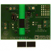
DIGITAL PICTURE OF THE EVALUATION BOARD
Figure 1. ADM3251E Evaluation Board
Please see the last page for an important warning and disclaimers.
Rev. 0 | Page 1 of 8
�UG-120
Evaluation Board User Guide
TABLE OF CONTENTS
Features .............................................................................................. 1
Printed Circuit Board Layout ..........................................................4
Evaluation Kit Contents ................................................................... 1
Evaluation Board Hardware .............................................................5
General Description ......................................................................... 1
Connector, Test Point, and Jumper Functions ..........................5
Digital Picture of the Evaluation Board ......................................... 1
Ordering Information .......................................................................6
Revision History ............................................................................... 2
Bill of Materials ..............................................................................6
Evaluation Board Schematic ........................................................... 3
ESD Caution...................................................................................8
REVISION HISTORY
3/10—Revision 0: Initial Version
Rev. 0 | Page 2 of 8
�Evaluation Board User Guide
UG-120
08961-002
EVALUATION BOARD SCHEMATIC
Figure 2. Schematic of the ADM3251E Evaluation Board
Rev. 0 | Page 3 of 8
�UG-120
Evaluation Board User Guide
08961-003
PRINTED CIRCUIT BOARD LAYOUT
Figure 3. EVAL-ADM3251EEBZ Silkscreen
Rev. 0 | Page 4 of 8
�Evaluation Board User Guide
UG-120
EVALUATION BOARD HARDWARE
CONNECTOR, TEST POINT, AND JUMPER FUNCTIONS
Table 1. Connector Functions
Connector
J1
Name
Power connector
J2
Terminal block
J3
Power connector
J4
Terminal block
Function
J1-1: Connects positive output of bench supply to the VCC pin of the ADM3251E.
J1-2: Connects ground terminal of bench supply to the GND pins of the ADM3251E.
J2-1: Connects to ROUT pin of the ADM3251E.
J2-2: Connects to TIN pin of the ADM3251E.
J3-1: Connects positive supply of isolated bench supply to Jumper J7-A, which,
when inserted, connects to the VISO pin of the ADM3251E.
J3-2: Connects ground terminal of bench supply to the GNDISO pin of the ADM3251E.
J4-1: Connects to TOUT pin of the ADM3251E.
J4-2: Connects to RIN pin of the ADM3251E.
Table 2. Test Point Functions
Test Point
GND, GND1
ISOGND
ISOVCC
ISOVCCPATCHWORK
PIN1
RIN
ROUT
TIN
TOUT
VCC
Function
Connected to GND pin of the ADM3251E.
Connected to GNDISO pin of the ADM3251E.
Connected to VISO pin of the ADM3251E.
Connected to Jumper J7-B.
Connected to Pin 1 of the ADM3251E.
Connected to RIN pin of the ADM3251E.
Connected to ROUT pin of the ADM3251E.
Connected to TIN pin of the ADM3251E.
Connected to TOUT pin of the ADM3251E.
Connected to VCC pin of the ADM3251E.
Table 3. Jumper Functions1
Jumper
J5
J6
J7
1
Function
Connects Pin 2 (VCC) to J1-1.
Connects Pin 3 (VCC) to J1-1.
J7-B: Connects Pin 20 (VISO) to ISOVCCPATCHWORK.
J7-A: Connects Pin 20 (VISO) to J3-1.
By default, Jumper 5, Jumper 6, and Jumper 7 are inserted.
Rev. 0 | Page 5 of 8
�UG-120
Evaluation Board User Guide
ORDERING INFORMATION
BILL OF MATERIALS
Table 4.
Qty
6
3
3
4
2
1
1
Reference Designator
C1 to C6
GND, GND1, ISOGND
VCC, ISOVCC, ISOVCCPATCHWORK
J1 to J4
J5, J6
J7
U1
Description
Capacitor, 0.1 μF
Black test point
Red test point
Terminal block
Jumper
Jumper
RS-232 transceiver
Rev. 0 | Page 6 of 8
Part Decal
0603
Testpoint
Testpoint
CON\POWER
SIP-2P
Jumper_2
SO20WB
Part No.
FEC 1414610
FEC 8731128
FEC 8731144
FEC 1177875
FEC 1022247 and 150411
FEC 1022244 and 150410
ADM3251EARWZ
�Evaluation Board User Guide
UG-120
NOTES
Rev. 0 | Page 7 of 8
�UG-120
Evaluation Board User Guide
NOTES
ESD CAUTION
Evaluation boards are only intended for device evaluation and not for production purposes. Evaluation boards are supplied “as is” and without warranties of any kind, express,
implied, or statutory including, but not limited to, any implied warranty of merchantability or fitness for a particular purpose. No license is granted by implication or otherwise under
any patents or other intellectual property by application or use of evaluation boards. Information furnished by Analog Devices is believed to be accurate and reliable. However, no
responsibility is assumed by Analog Devices for its use, nor for any infringements of patents or other rights of third parties that may result from its use. Analog Devices reserves the
right to change devices or specifications at any time without notice. Trademarks and registered trademarks are the property of their respective owners. Evaluation boards are not
authorized to be used in life support devices or systems.
©2010 Analog Devices, Inc. All rights reserved. Trademarks and
registered trademarks are the property of their respective owners.
UG08961-0-3/10(0)
Rev. 0 | Page 8 of 8
�
很抱歉,暂时无法提供与“EVAL-ADM3251EEBZ”相匹配的价格&库存,您可以联系我们找货
免费人工找货