Circuit Note
CN-0270
Circuits from the Lab® reference designs are engineered and
tested for quick and easy system integration to help solve today’s
analog, mixed-signal, and RF design challenges. For more
information and/or support, visit www.analog.com/CN0270.
Devices Connected/Referenced
AD5700,
Low Power HART® Modem
AD5700-1
AD5420
16-Bit 4 mA to 20 mA DAC
Complete 4 mA to 20 mA HART Solution
EVALUATION AND DESIGN SUPPORT
CIRCUIT FUNCTION AND BENEFITS
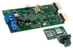
Circuit Evaluation Boards
CN-0270 Evaluation Board (EVAL-CN0270-EB1Z) includes
USB-SWD/UART-EMUZ
Design and Integration Files
Schematics, Layout Files, Bill of Materials
The circuit shown in Figure 1 uses the AD5700, the industry’s
lowest power and smallest footprint HART1-compliant IC modem
and the AD5420, a 16-bit current-output DAC, to form a complete
HART-compatible 4 mA to 20 mA solution, typical of line-powered
transmitter applications
For additional space savings, the AD5700-1 offers a 0.5% precision
internal oscillator.
10µF
*NC
10µF
2.7V TO 5.5V
10kΩ
DVCC CAP2
10.8V TO 36V
C1
4.7nF
*C2
0.1µF
0.1µF
AVDD
CAP1
FAULT
REFIN
CLEAR
DIGITAL
INTERFACE
REFOUT
0.1µF
LATCH
SCLK
SDIN
AD5420
18Ω
IOUT
SDO
UART
INTERFACE
4mA TO 20mA
CURRENT LOOP
RL
RSET
GND
0.1µF
15kΩ
VCC
TXD
HART_OUT
RH
27kΩ
CH
8.2nF
CL
4.7nF
RXD
RTS
REF
1µF
AD5700
1.2MΩ
300pF
ADC_IP
AGND
DGND
1.2MΩ
150kΩ
150pF
10564-001
CD
Figure 1. AD5420 HART-Enabled Circuit Simplified Schematic
1
HART® is a registered trademark of the HART Communication Foundation.
Rev. B
Circuits from the Lab reference designs from Analog Devices have been designed and built by Analog
Devices engineers. Standard engineering practices have been employed in the design and
construction of each circuit, and their function and performance have been tested and verified in a lab
environment at room temperature. However, you are solely responsible for testing the circuit and
determining its suitability and applicability for your use and application. Accordingly, in no event shall
Analog Devices be liable for direct, indirect, special, incidental, consequential or punitive damages due
toanycausewhatsoeverconnectedtotheuseofanyCircuitsfromtheLabcircuits. (Continuedonlastpage)
One Technology Way, P.O. Box 9106, Norwood, MA 02062-9106, U.S.A.
Tel: 781.329.4700
www.analog.com
Fax: 781.461.3113 ©2012–2014 Analog Devices, Inc. All rights reserved.
�CN-0270
Circuit Note
This circuit adheres to the HART physical layer specifications as
defined by the HART Communication Foundation, for example,
the analog rate of change and noise during silence specifications.
For many years, 4 mA to 20 mA communication has been used
in process control instrumentation. This communication method is
reliable and robust, and offers high immunity to environmental
interference over long communication distances. A limitation,
however, is that only 1-way communication of one process
variable at a time is possible.
Determining the Values of the External Components
C1 and C2 can be used in conjunction with the digital slew rate
control functionality of the part to control the slew rate of the
IOUT signal of the AD5420. In determining the absolute values of
the capacitors, ensure that the FSK output from the modem is
passed undistorted. Thus, the bandwidth presented to the modem
output signal must pass the 1200 Hz and 2200 Hz frequencies.
Figure 3 shows a circuit that achieves this requirement. In this
case, C2 is left open-circuit.
The development of the highway addressable remote transducer
(HART) standard provided highly capable 2-way digital
communication, simultaneously with the 4 mA to 20 mA analog
signaling used by traditional instrumentation equipment. This
allows for features such as remote calibration, fault interrogation,
and transmission of additional process variables. Put simply,
HART is a digital two-way communication in which a 1 mA
peak-to-peak frequency-shift-keyed (FSK) signal is modulated
on top of the 4 mA to 20 mA analog current signal.
C1
C2
CAP1
CAP2
AVDD
40Ω
BOOST
4kΩ
12.5kΩ
DAC
IOUT
"1" = MARK
1.2kHz
RSET
CH
RH
CL
VHART
Figure 3. AD5420/AD5410 and AD5700 HART Modem Connection
The low-pass and high-pass filter circuitry is formed through
the interaction of RH, CL, CH, and C1, along with some internal
circuitry in the AD5420. In calculating the values of these
components, the low-pass and high-pass frequency cutoff point
targets were >10 kHz and
很抱歉,暂时无法提供与“EVAL-CN0270-EB1Z”相匹配的价格&库存,您可以联系我们找货
免费人工找货