HMC-C018
v03.0310
0.5dB LSB GaAs MMIC 6-BIT DIGITAL
SERIAL CONTROL ATTENUATOR MODULE, DC - 13 GHz
Features
Attenuators
2
0.5 dB LSB Steps to 31.5 dB
CMOS Compatible Serial Data Interface
Typical Bit Error: ±0.3 dB
Hermetically Sealed Module
Field Replaceable SMA Connectors
Typical Applications
-55 °C to +85 °C Operating Temperature
The HMC-C018 is ideal for:
• Telecom Infrastructure
• Military Radio, Radar & ECM
• Space Systems
General Description
• Test Instrumentation
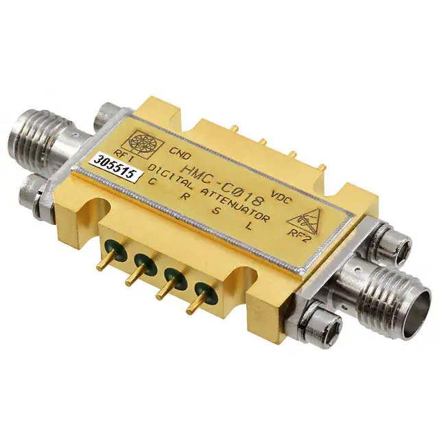
The HMC-C018 is a DC to 13 GHz 6-bit GaAs IC
Digital Serial Control Attenuator housed in a miniature
hermetic module. This wideband attenuator features
3.6 dB typical insertion loss, +38 dBm input IP3,
and bit values of 0.5 (LSB), 1, 2, 4, 8, and 16 dB for
a total attenuation of 31.5 dB. Attenuation accuracy
is excellent with ±0.3 dB typical step error. A six
bit CMOS compatible serial control word is used to
select each attenuation state and a single Vdc bias
of -5V allows operation at frequencies down to DC.
Removable SMA connectors can be detached to
allow direct connection of the module’s I/O pins to a
microstrip or coplanar circuit.
Functional Diagram
Electrical Specifications, TA = +25 °C, with Vdc = -5V and 0/+5V CMOS Control
Parameter
Frequency (GHz)
Typ.
Max.
Units
Insertion Loss
DC - 4.0 GHz
4.0 - 8.0 GHz
8.0 - 13 .0 GHz
3.2
3.6
5.0
3.7
4.1
6.0
dB
dB
dB
Attenuation Range
DC - 13.0 GHz
31.5
dB
Return Loss (RF1 & RF2, All Atten. States)
DC - 8.0 GHz
8.0 - 13.0 GHz
15
10
dB
dB
DC - 3.0 GHz
3.0 - 10.0 GHz
3.0 - 10.0 GHz
10.0 - 13.0 GHz
± (0.2 + 3% of Atten. Setting) Max
± (0.4 + 3% of Atten. Setting) Max
± (0.5 + 6% of Atten. Setting) Max
± (0.6 + 6% of Atten. Setting) Max
dB
dB
dB
dB
Attenuation Accuracy: (Referenced to Insertion Loss)
All States
0.5 - 27.5 dB
28.0 - 31.5 dB
All States
Input Power for 0.1 dB Compression
Input Third Order Intercept Point
(Two-Tone Input Power= 0 dBm Each Tone)
REF State
All Other States
Switching Characteristics
tRISE, tFALL (10/90% RF)
tON/tOFF (50% CTL to 10/90% RF)
2-1
Min.
1.0 - 13.0 GHz
22
dBm
1.0 - 13.0 GHz
46
32
dBm
dBm
600
700
ns
ns
DC - 13.0 GHz
For price,
delivery,
and to placeCorporation:
orders: Analog Devices, Inc.,
For price, delivery, and to place orders, please contact
Hittite
Microwave
One Technology Way, P.O. Box 9106, Norwood, MA 02062-9106
20 Alpha Road Chelmsford, MA 01824 Phone: Phone:
978-250-3343
978-250-3373
781-329-4700Fax:
• Order
online at www.analog.com
Application Support: Phone: 1-800-ANALOG-D
Order Online at www.hittite.com
Information furnished by Analog Devices is believed to be accurate and reliable. However, no
responsibility is assumed by Analog Devices for its use, nor for any infringements of patents or other
rights of third parties that may result from its use. Specifications subject to change without notice. No
license is granted by implication or otherwise under any patent or patent rights of Analog Devices.
Trademarks and registered trademarks are the property of their respective owners.
�HMC-C018
v03.0310
0.5dB LSB GaAs MMIC 6-BIT DIGITAL
SERIAL CONTROL ATTENUATOR MODULE, DC - 13 GHz
Return Loss RF1, RF2
(Only Major States are Shown)
-5
-4
-6
+25 C
+85 C
-55 C
-8
-10
31.5 dB
-10
2 dB
I.L 0.5 dB
8 dB
16 dB
-15
-20
-30
0
3
6
9
12
15
18
21
0
3
6
FREQUENCY (GHz)
9
12
15
FREQUENCY (GHz)
Normalized Attenuation
Bit Error vs. Attenuation State
(Only Major States are Shown)
0
2
-5
1.5
1
-10
BIT ERROR (dB)
NORMALIZED ATTENUATION (dB)
4 dB 1 dB
-25
-12
-15
-20
-25
0.5
0
-0.5
-1
-30
0.1 GHz
4 GHz
8 GHz
13 GHz
-1.5
-35
-2
0
3
6
9
12
15
0
4
8
12
16
20
24
28
32
ATTENUATION STATE (dB)
FREQUENCY (GHz)
Bit Error vs. Frequency
Relative Phase vs. Frequency
(Only Major States are Shown)
(Only Major States are Shown)
80
3
2
31.5 dB
0.5-16 dB
1
RELATIVE PHASE (deg)
BIT ERROR (dB)
2
0
RETURN LOSS (dB)
INSERTION LOSS (dB)
-2
Attenuators
Insertion Loss
0
-1
-2
-3
60
40
8 dB
0
0.5 - 4 dB
-20
0
3
6
9
12
15
FREQUENCY (GHz)
16 dB
31.5 dB
20
0
3
6
9
12
15
FREQUENCY (GHz)
For price,
delivery,
and to placeCorporation:
orders: Analog Devices, Inc.,
For price, delivery, and to place orders, please contact
Hittite
Microwave
One Technology Way, P.O. Box 9106, Norwood, MA 02062-9106
20 Alpha Road Chelmsford, MA 01824 Phone: 978-250-3343
Fax:
978-250-3373
Phone: 781-329-4700
• Order
online at www.analog.com
Application Support: Phone: 1-800-ANALOG-D
Order Online at www.hittite.com
Information furnished by Analog Devices is believed to be accurate and reliable. However, no
responsibility is assumed by Analog Devices for its use, nor for any infringements of patents or other
rights of third parties that may result from its use. Specifications subject to change without notice. No
license is granted by implication or otherwise under any patent or patent rights of Analog Devices.
Trademarks and registered trademarks are the property of their respective owners.
2-2
�HMC-C018
v03.0310
0.5dB LSB GaAs MMIC 6-BIT DIGITAL
SERIAL CONTROL ATTENUATOR MODULE, DC - 13 GHz
2
Worst Case Step Error
Between Successive Attenuation States
Absolute Maximum Ratings
1
STEP ERROR (dB)
Attenuators
0.5
0
Digital Inputs (Reset, Shift Clock,
Latch Enable & Serial Input)
-0.5V to +5.5V
Bias Voltage (VDC)
-7.0 Vdc
Storage Temperature
-65 to + 150 °C
Operating Temperature
-55 to +85 °C
RF Input Power (0.5 - 13.0 GHz)
+25 dBm
-0.5
ELECTROSTATIC SENSITIVE DEVICE
OBSERVE HANDLING PRECAUTIONS
-1
0
3
6
9
12
15
FREQUENCY (GHz)
CMOS Control Voltages
Bias Voltage & Current
VDC Range= -5.0 Vdc ± 10%
VDC
State
Idc (Typ.)
(mA)
Idc (Max.)
(mA)
5
9
-5.0
Serial Input Truth Table
Shift
Clock
Reset
Function
X
X
L
Shift register cleared
X
á
H
Shift register clocked
X
H
0 to +1.3V
High
+3.5 to +5.0V
Truth Table
Latch
Enable
á
Bias Condition
Low
Contents of shift register
transferred to Digital
Attenuator
Serial Control Input
C0.5
C1
C2
C4
C8
C16
Attenuation
Settings
RF1 - RF2
H
H
H
H
H
H
Reference I.L.
L
H
H
H
H
H
0.5 dB
H
L
H
H
H
H
1 dB
H
H
L
H
H
H
2 dB
H
H
H
L
H
H
4 dB
H
H
H
H
L
H
8 dB
H
H
H
H
H
L
16 dB
L
L
L
L
L
L
31.5 dB
Any combination of the above states will provide an attenuation
approximately equal to the sum of the bits selected.
2-3
For price,
delivery,
and to placeCorporation:
orders: Analog Devices, Inc.,
For price, delivery, and to place orders, please contact
Hittite
Microwave
One Technology Way, P.O. Box 9106, Norwood, MA 02062-9106
20 Alpha Road Chelmsford, MA 01824 Phone: Phone:
978-250-3343
978-250-3373
781-329-4700Fax:
• Order
online at www.analog.com
Application Support: Phone: 1-800-ANALOG-D
Order Online at www.hittite.com
Information furnished by Analog Devices is believed to be accurate and reliable. However, no
responsibility is assumed by Analog Devices for its use, nor for any infringements of patents or other
rights of third parties that may result from its use. Specifications subject to change without notice. No
license is granted by implication or otherwise under any patent or patent rights of Analog Devices.
Trademarks and registered trademarks are the property of their respective owners.
�HMC-C018
v03.0310
0.5dB LSB GaAs MMIC 6-BIT DIGITAL
SERIAL CONTROL ATTENUATOR MODULE, DC - 13 GHz
Parameter
Symbol
Min.
Max.
Units
Serial Input Setup
Time
ts
20
-
ns
Hold time from Serial
Input to Shift Clock
th
0
-
ns
Setup time from Shift
Clock to Latch Enable
tlsup
40
-
ns
Propagation delay,
Latch Enable to C0.5
through C8
tpd
-
30
ns
-
20
-
ns
fclk
-
30
MHz
Setup time from Reset
to Shift Clock
Clock Frequency
(1/tclk)
2
Attenuators
Timing
Timing Diagram
For price,
delivery,
and to placeCorporation:
orders: Analog Devices, Inc.,
For price, delivery, and to place orders, please contact
Hittite
Microwave
One Technology Way, P.O. Box 9106, Norwood, MA 02062-9106
20 Alpha Road Chelmsford, MA 01824 Phone: 978-250-3343
Fax:
978-250-3373
Phone: 781-329-4700
• Order
online at www.analog.com
Application Support: Phone: 1-800-ANALOG-D
Order Online at www.hittite.com
Information furnished by Analog Devices is believed to be accurate and reliable. However, no
responsibility is assumed by Analog Devices for its use, nor for any infringements of patents or other
rights of third parties that may result from its use. Specifications subject to change without notice. No
license is granted by implication or otherwise under any patent or patent rights of Analog Devices.
Trademarks and registered trademarks are the property of their respective owners.
2-4
�HMC-C018
v03.0310
0.5dB LSB GaAs MMIC 6-BIT DIGITAL
SERIAL CONTROL ATTENUATOR MODULE, DC - 13 GHz
Attenuators
2
Logic / Functional Diagram
2-5
For price,
delivery,
and to placeCorporation:
orders: Analog Devices, Inc.,
For price, delivery, and to place orders, please contact
Hittite
Microwave
One Technology Way, P.O. Box 9106, Norwood, MA 02062-9106
20 Alpha Road Chelmsford, MA 01824 Phone: Phone:
978-250-3343
978-250-3373
781-329-4700Fax:
• Order
online at www.analog.com
Application Support: Phone: 1-800-ANALOG-D
Order Online at www.hittite.com
Information furnished by Analog Devices is believed to be accurate and reliable. However, no
responsibility is assumed by Analog Devices for its use, nor for any infringements of patents or other
rights of third parties that may result from its use. Specifications subject to change without notice. No
license is granted by implication or otherwise under any patent or patent rights of Analog Devices.
Trademarks and registered trademarks are the property of their respective owners.
�HMC-C018
v03.0310
0.5dB LSB GaAs MMIC 6-BIT DIGITAL
SERIAL CONTROL ATTENUATOR MODULE, DC - 13 GHz
2
Attenuators
Programming Example to Select 0.5 dB Attenuation State
For price,
delivery,
and to placeCorporation:
orders: Analog Devices, Inc.,
For price, delivery, and to place orders, please contact
Hittite
Microwave
One Technology Way, P.O. Box 9106, Norwood, MA 02062-9106
20 Alpha Road Chelmsford, MA 01824 Phone: 978-250-3343
Fax:
978-250-3373
Phone: 781-329-4700
• Order
online at www.analog.com
Application Support: Phone: 1-800-ANALOG-D
Order Online at www.hittite.com
Information furnished by Analog Devices is believed to be accurate and reliable. However, no
responsibility is assumed by Analog Devices for its use, nor for any infringements of patents or other
rights of third parties that may result from its use. Specifications subject to change without notice. No
license is granted by implication or otherwise under any patent or patent rights of Analog Devices.
Trademarks and registered trademarks are the property of their respective owners.
2-6
�HMC-C018
v03.0310
0.5dB LSB GaAs MMIC 6-BIT DIGITAL
SERIAL CONTROL ATTENUATOR MODULE, DC - 13 GHz
Attenuators
2
2-7
Pin Description
Pin Number
Function
Description
1
RF1
This pin is DC coupled and matched to 50 Ohms.
Blocking capacitors are required if RF line potential
is not equal to 0 Vdc.
2
C
Shift Clock
3
R
Reset
4
S
Serial Input
5
L
Latch Enable
6
RF2
This pin is DC coupled and matched to 50 Ohms.
Blocking capacitors are required if RF line potential
is not equal to 0 Vdc.
7
Vdc
Supply voltage: -5 Vdc ±10%.
(Internal diode for reverse bias protection)
8
GND
Power Supply Ground
Interface Schematic
For price,
delivery,
and to placeCorporation:
orders: Analog Devices, Inc.,
For price, delivery, and to place orders, please contact
Hittite
Microwave
One Technology Way, P.O. Box 9106, Norwood, MA 02062-9106
20 Alpha Road Chelmsford, MA 01824 Phone: Phone:
978-250-3343
978-250-3373
781-329-4700Fax:
• Order
online at www.analog.com
Application Support: Phone: 1-800-ANALOG-D
Order Online at www.hittite.com
Information furnished by Analog Devices is believed to be accurate and reliable. However, no
responsibility is assumed by Analog Devices for its use, nor for any infringements of patents or other
rights of third parties that may result from its use. Specifications subject to change without notice. No
license is granted by implication or otherwise under any patent or patent rights of Analog Devices.
Trademarks and registered trademarks are the property of their respective owners.
�HMC-C018
v03.0310
0.5dB LSB GaAs MMIC 6-BIT DIGITAL
SERIAL CONTROL ATTENUATOR MODULE, DC - 13 GHz
Outline Drawing
Attenuators
2
Package Information
Package Type
C-6
Package Weight [1]
17.4 gms [2]
Spacer Weight
3 gms [2]
[1] Includes the connectors
[2] ±1 gms Tolerance
NOTES:
1. PACKAGE, LEADS, COVER MATERIAL: KOVAR™
2. PLATING: ELECTROLYTIC GOLD 50 MICROINCHES MIN., OVER
ELECTROLYTIC NICKEL 75 MICROINCHES MIN
3. MOUNTING SPACER: NICKEL PLATED ALUMINUM
4. ALL DIMENSIONS ARE IN INCHES [MILLIMETERS]
5. TOLERANCES ±0.010 [0.25] UNLESS OTHERWISE SPECIFIED
6. FIELD REPLACEABLE SMA CONNECTORS
TENSOLITE 5602 - 5CCSF OR EQUIVALENT
7. TO MOUNT MODULE TO SYSTEM PLATFORM REPLACE 0 -80
HARDWARE WITH DESIRED MOUNTING SCREWS
For price,
delivery,
and to placeCorporation:
orders: Analog Devices, Inc.,
For price, delivery, and to place orders, please contact
Hittite
Microwave
One Technology Way, P.O. Box 9106, Norwood, MA 02062-9106
20 Alpha Road Chelmsford, MA 01824 Phone: 978-250-3343
Fax:
978-250-3373
Phone: 781-329-4700
• Order
online at www.analog.com
Application Support: Phone: 1-800-ANALOG-D
Order Online at www.hittite.com
Information furnished by Analog Devices is believed to be accurate and reliable. However, no
responsibility is assumed by Analog Devices for its use, nor for any infringements of patents or other
rights of third parties that may result from its use. Specifications subject to change without notice. No
license is granted by implication or otherwise under any patent or patent rights of Analog Devices.
Trademarks and registered trademarks are the property of their respective owners.
2-8
�