HMC143 / HMC144
v05.1007
GaAs MMIC DOUBLE-BALANCED
MIXER, 5 - 20 GHz
Typical Applications
Features
The HMC143 & HMC144 is ideal for:
Input IP3: +25 dBm
• Microwave Point-to-Point Radios
LO / RF Isolation: 30 dB
• VSAT
IF Bandwidth: DC to 3 GHz
Small Size: 2.10 x 1.45 x 0.1 mm
B
SO
LE
The HMC143 chip is a minature double-balanced
mixer which can be used as an upconverter or downconverter. The chip utilizes a standard 1μm GaAs
MESFET process. The HMC144 is identical to the
HMC143 except that the layout is a mirror image
designed to ease integration into image-reject
mixer modules. Broadband operation and excellent
isolations are provided by on-chip baluns, which
require no external components and no DC bias. The
design is similar to the HMC141/142 mixers but with an
IF combiner in a double-balanced design, providing
improved RF/IF isolation. These devices are much
smaller and more reliable replacements to hybrid
diode mixers.
Electrical Specifi cations, TA = +25° C, LO Drive = +20 dBm
Parameter
Min.
Typ.
Max.
Min.
Typ.
Max.
Min.
Typ.
Max.
Units
Frequency Range, RF & LO
5 - 10.5
10.5 - 15.5
15.5 - 20
GHz
Frequency Range, IF
DC - 3
DC - 3
DC - 3
GHz
Conversion Loss
10
12
10
12
10
12
dB
Noise Figure (SSB)
10
12
10
12
10
12
dB
LO to RF Isolation
26
30
24
28
26
30
dB
LO to IF Isolation
15
18
12
15
14
17
dB
IP3 (Input)
21
25
23
dBm
IP2 (Input)
50
50
50
dBm
15
dBm
1 dB Gain Compression (Input)
4 - 28
General Description
TE
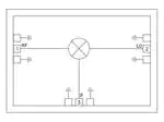
Functional Diagram
O
MIXERS - DOUBLE-BALANCED - CHIP
4
10
15
10
15
10
For price, delivery, and to place orders, please contact Hittite Microwave Corporation:
20 Alpha Road, Chelmsford, MA 01824 Phone: 978-250-3343 Fax: 978-250-3373
Order On-line at www.hittite.com
�HMC143 / HMC144
v05.1007
GaAs MMIC DOUBLE-BALANCED
MIXER, 5 - 20 GHz
Conversion Gain vs.
Temperature @ LO = +20 dBm
Isolation @ LO = +20 dBm
0
-10
-30
TE
+25 C
+85 C
-55 C
-15
-20
-50
4
6
8
10
12
14
16
18
20
4
22
6
8
10
12
14
16
18
20
22
FREQUENCY (GHz)
LE
FREQUENCY (GHz)
Conversion Gain vs. LO Drive
Return Loss @ LO = +20 dBm
0
0
LO = +13 dBm
LO = +15 dBm
LO = +17 dBm
LO = +20 dBm
-10
-15
4
6
8
10
12
14
16
18
20
LO
-10
-15
-20
-25
4
22
6
8
FREQUENCY (GHz)
10
12
14
16
18
20
22
FREQUENCY (GHz)
Upconverter Performance
Conversion Gain @ LO = +20 dBm
O
IF Bandwidth @ LO = +20 dBm
0
0
CONVERSION GAIN (dB)
-5
-10
-15
-20
IF CONVERSION GAIN
-25
RF
-5
B
SO
-5
-20
RESPONSE (dB)
4
-40
-5
MIXERS - DOUBLE-BALANCED - CHIP
ISOLATION (dB)
-5
-20
CONVERSION GAIN (dB)
RF to IF
LO to RF
LO to IF
-10
RETURN LOSS (dB)
CONVERSION GAIN (dB)
0
-10
-15
IF RETURN LOSS
-30
-20
0
1
2
3
4
FREQUENCY (GHz)
5
6
4
6
8
10
12
14
16
18
20
22
FREQUENCY (GHz)
For price, delivery, and to place orders, please contact Hittite Microwave Corporation:
20 Alpha Road, Chelmsford, MA 01824 Phone: 978-250-3343 Fax: 978-250-3373
Order On-line at www.hittite.com
4 - 29
�HMC143 / HMC144
v05.1007
GaAs MMIC DOUBLE-BALANCED
MIXER, 5 - 20 GHz
Input IP3 vs.
Temperature @ LO = +20 dBm
35
30
30
25
25
20
15
10
20
15
+25 C
+85 C
-55 C
10
TE
LO = +13 dBm
LO = +15 dBm
LO = +17 dBm
LO = +20 dBm
5
5
0
0
4
6
8
10
12
14
16
18
20
4
22
6
8
10
12
14
16
18
20
22
18
20
22
FREQUENCY (GHz)
LE
FREQUENCY (GHz)
Input P1dB vs.
Temperature @ LO = +20 dBm
Input IP2 vs. LO Drive*
25
80
70
40
30
B
SO
50
LO = +13 dBm
LO = +15 dBm
LO = +17 dBm
LO = +20 dBm
20
10
0
4
6
8
10
12
14
16
18
20
22
15
10
+25C
+85C
-55C
5
0
4
6
8
10
12
14
16
FREQUENCY (GHz)
O
FREQUENCY (GHz)
P1dB (dBm)
20
60
IP3 (dBm)
MIXERS - DOUBLE-BALANCED - CHIP
4
35
IP3 (dBm)
IP3 (dBm)
Input IP3 vs. LO Drive*
* Two-tone input power = 0 dBm each tone, 1 MHz spacing.
4 - 30
For price, delivery, and to place orders, please contact Hittite Microwave Corporation:
20 Alpha Road, Chelmsford, MA 01824 Phone: 978-250-3343 Fax: 978-250-3373
Order On-line at www.hittite.com
�HMC143 / HMC144
v05.1007
GaAs MMIC DOUBLE-BALANCED
MIXER, 5 - 20 GHz
MxN Spurious @ IF Port
Harmonics of LO
nLO Spur @ RF Port
1
2
3
4
LO Freq. (GHz)
1
2
3
4
0
XX
-11
18
2
22
6
37
35
58
38
1
43
0
46
15
31
8
38
36
54
46
2
67
61
63
69
68
10
33
36
50
56
3
77
74
80
68
80
12
28
28
41
N/A
4
72
77
77
80
80
14
30
40
N/A
N/A
TE
0
RF = 6 GHz @ -10 dBm
LO = 6.1 GHz @ 20 dBm
All values in dBc relative to the IF power level.
Measured as downconverter.
16
33
41
N/A
N/A
18
32
47
N/A
N/A
20
29
43
N/A
N/A
Absolute Maximum Ratings
LE
LO = +20 dBm
All values in dBc below input LO level @ RF port.
+15 dBm
LO Drive
+27 dBm
IF DC Current
± 2 mA
Channel Temperature
150 °C
924 mW
Thermal Resistance (RTH)
(junction to package bottom)
70.4 °C/W
Storage Temperature
-65 to +150 °C
Operating Temperature
-55 to +85 °C
ESD Sensitivity (HBM)
Class 1A
Standard
Alternate
WP-4
[2]
ELECTROSTATIC SENSITIVE DEVICE
OBSERVE HANDLING PRECAUTIONS
O
Continuous Pdiss (T=85 °C)
(derate 14.2 mW/°C above 85 °C)
[1]
[1] Refer to the “Packaging Information” section for die
packaging dimensions.
[2] For alternate packaging information contact Hittite
Microwave Corporation.
B
SO
RF / IF Input
Die Packaging Information
For price, delivery, and to place orders, please contact Hittite Microwave Corporation:
20 Alpha Road, Chelmsford, MA 01824 Phone: 978-250-3343 Fax: 978-250-3373
Order On-line at www.hittite.com
4
MIXERS - DOUBLE-BALANCED - CHIP
nLO
mRF
4 - 31
�HMC143 / HMC144
v05.1007
Outline Drawings
GaAs MMIC DOUBLE-BALANCED
MIXER, 5 - 20 GHz
(See HMC143/144 Operation Application Note)
HMC143
4 - 32
TE
LE
B
SO
HMC144
NOTES:
1. ALL DIMENSIONS ARE IN INCHES [MM].
2. DIE THICKNESS IS .004”.
3. TYPICAL BOND PAD IS .004” SQUARE.
4. BACKSIDE METALLIZATION: GOLD.
5. BOND PAD METALLIZATION: GOLD.
6. BACKSIDE METAL IS GROUND.
7. CONNECTION NOT REQUIRED FOR
UNLABELED BOND PADS.
O
MIXERS - DOUBLE-BALANCED - CHIP
4
For price, delivery, and to place orders, please contact Hittite Microwave Corporation:
20 Alpha Road, Chelmsford, MA 01824 Phone: 978-250-3343 Fax: 978-250-3373
Order On-line at www.hittite.com
�HMC143 / HMC144
v05.1007
GaAs MMIC DOUBLE-BALANCED
MIXER, 5 - 20 GHz
Pad Descriptions HMC143 (HMC144)
Description
1 (2)
LO
This pin is AC coupled
and matched to 50 Ohms.
2 (1)
RF
This pin is AC coupled
and matched to 50 Ohms.
IF
This pin is DC coupled. For applications not requiring operation
to DC, this port should be DC blocked externally using a series
capacitor whose value has been chosen to pass the necessary IF
frequency range. For operation to DC, this pin must not source/
sink more than 2 mA of current or die non-function and possible
die failure will result.
GND
The backside of the die must be connected to RF ground.
LE
O
B
SO
3 (3)
Interface Schematic
For price, delivery, and to place orders, please contact Hittite Microwave Corporation:
20 Alpha Road, Chelmsford, MA 01824 Phone: 978-250-3343 Fax: 978-250-3373
Order On-line at www.hittite.com
4
MIXERS - DOUBLE-BALANCED - CHIP
Function
TE
Pad Number
4 - 33
�HMC143 / HMC144
v05.1007
GaAs MMIC DOUBLE-BALANCED
MIXER, 5 - 20 GHz
Assembly Drawing
4 - 34
TE
LE
B
SO
O
MIXERS - DOUBLE-BALANCED - CHIP
4
For price, delivery, and to place orders, please contact Hittite Microwave Corporation:
20 Alpha Road, Chelmsford, MA 01824 Phone: 978-250-3343 Fax: 978-250-3373
Order On-line at www.hittite.com
�HMC143 / HMC144
v05.1007
GaAs MMIC DOUBLE-BALANCED
MIXER, 5 - 20 GHz
Handling Precautions
Follow these precautions to avoid permanent damage.
Storage: All bare die are placed in either Waffle or Gel based ESD protective containers, and then sealed in an ESD protective bag
for shipment. Once the sealed ESD protective bag has been opened, all die should be stored in a dry nitrogen environment.
Cleanliness: Handle the chips in a clean environment. DO NOT attempt to clean the chip using liquid cleaning systems.
Static Sensitivity: Follow ESD precautions to protect against ESD strikes.
TE
General Handling: Handle the chip along the edges with a vacuum collet or with a sharp pair of bent tweezers. The surface of the
chip has fragile air bridges and should not be touched with vacuum collet, tweezers, or fingers.
Mounting
The chip is back-metallized and can be die mounted with AuSn eutectic preforms or with electrically conductive epoxy. The mounting
surface should be clean and flat.
Wire Bonding
LE
Eutectic Die Attach: A 80/20 gold tin preform is recommended with a work surface temperature of 255 °C and a tool temperature
of 265 °C. When hot 90/10 nitrogen/hydrogen gas is applied, tool tip temperature should be 290 °C. DO NOT expose the chip
to a temperature greater than 320 °C for more than 20 seconds. No more than 3 seconds of scrubbing should be required for
attachment.
Epoxy Die Attach: Apply a minimum amount of epoxy to the mounting surface so that a thin epoxy fillet is observed around the
perimeter of the chip once it is placed into position. Cure epoxy per the manufacturer’s schedule.
O
B
SO
RF bonds made with 0.003” x 0.0005” ribbon are recommended. These bonds should be thermosonically bonded with a force of
40-60 grams. DC bonds of 0.001” (0.025 mm) diameter, thermosonically bonded, are recommended. Ball bonds should be made
with a force of 40-50 grams and wedge bonds at 18-22 grams. All bonds should be made with a nominal stage temperature of 150
°C. A minimum amount of ultrasonic energy should be applied to achieve reliable bonds. All bonds should be as short as possible,
less than 12 mils (0.31 mm).
For price, delivery, and to place orders, please contact Hittite Microwave Corporation:
20 Alpha Road, Chelmsford, MA 01824 Phone: 978-250-3343 Fax: 978-250-3373
Order On-line at www.hittite.com
4
MIXERS - DOUBLE-BALANCED - CHIP
Transients: Suppress instrument and bias supply transients while bias is applied. Use shielded signal and bias cables to minimize
inductive pick-up.
4 - 35
�


 工商网监
湘ICP备2023018690号
工商网监
湘ICP备2023018690号
