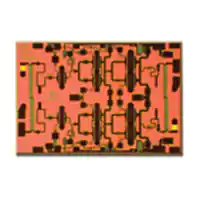
HMC864
v01.0110
Typical Applications
Features
The HMC864 is ideal for:
Saturated Output Power: +31 dBm @ 18% PAE
• Point-to-Point Radios
High Output IP3: +40 dBm
• Point-to-Multi-Point Radios
High Gain: 27 dB
• VSAT
DC Supply: +6V @ 750mA
• Military & Space
No External Matching Required
TE
Die Size: 2.41 x 1.65 x 0.1 mm
Functional Diagram
General Description
B
SO
LE
The HMC864 is a three stage GaAs pHEMT MMIC
1 Watt Power Amplifier which operates between
24 and 29.5 GHz. The HMC864 provides 27 dB of
gain, and +31 dBm of saturated output power and
18% PAE from a +6V supply. The RF I/Os are DC
blocked and matched to 50 Ohms for ease of integration into Multi-Chip-Modules (MCMs). All data is taken
with the chip in a 50 Ohm test fixture connected via
0.025 mm (1 mil) diameter wire bonds of length 0.31
mm (12 mils).
Electrical Specifications, TA = +25° C, Vdd = Vdd1 = Vdd2 = +6V, Idd = 750mA [1]
O
Amplifiers - Linear & Power - Chip
3
GaAs pHEMT MMIC 1 WATT
POWER AMPLIFIER, 24 - 29.5 GHz
Parameter
Min.
Frequency Range
Gain
24
Gain Variation Over Temperature
Input Return Loss
Output Return Loss
Max.
Min.
27
Saturated Output Power (Psat)
(IP3)[2]
Total Supply Current (Idd)
27
Typ.
27 - 29.5
22
Max.
Units
GHz
25
dB
0.021
0.027
dB/ °C
27
25
dB
19
Output Power for 1 dB Compression (P1dB)
Output Third Order Intercept
Typ.
24 - 27
14
dB
29
dBm
30
dBm
39
40
dBm
750
750
mA
29
31
27
[1] Adjust Vgg between -2 to 0V to achieve Idd = 750mA typical.
[2] Measurement taken at +6V @ 750mA, Pout / Tone = +19 dBm
3-1
Information furnished by Analog Devices is believed to be accurate and reliable. However, no
For price, delivery,
andRoad,
to placeChelmsford,
orders: AnalogMA
Devices,
Inc.,
For price,
delivery
toforplace
orders:
Hittite Microwave
Corporation,
20 Alpha
01824
responsibility
is assumed
by Analogand
Devices
its use, nor
for any infringements
of patents or other
One Technology Way, P.O. Box 9106, Norwood, MA 02062-9106
rights of third parties that may result from its use. Specifications subject to change without notice. No
Phone: 978-250-3343
Fax: 978-250-3373 Phone:
Order781-329-4700
On-line at www.hittite.com
• Order online at www.analog.com
license is granted by implication or otherwise under any patent or patent rights of Analog Devices.
Application
Support: Phone: 1-800-ANALOG-D
Trademarks and registered trademarks areApplication
the property of their
respective owners.
Support:
Phone: 978-250-3343
or apps@hittite.com
�HMC864
v01.0110
GaAs pHEMT MMIC 1 WATT
POWER AMPLIFIER, 24 - 29.5 GHz
Gain vs. Temperature
34
20
32
0
GAIN (dB)
S21
S11
S22
-10
28
26
24
TE
-20
22
-30
+25C
+85C
-55C
20
-40
18
21
24
27
30
24
FREQUENCY (GHz)
25
27
28
29
30
LE
Output Return Loss vs. Temperature
0
0
-5
+25C
+85C
-55C
-5
-10
+25C
+85C
-55C
-20
-25
-30
-40
24
B
SO
-15
-35
25
26
27
28
29
-10
-15
-20
-25
24
30
25
33
31
31
P1dB (dBm)
33
29
27
+25C
+85C
-55C
25
27
28
29
30
29
30
P1dB vs. Supply Voltage
O
P1dB vs. Temperature
26
FREQUENCY (GHz)
FREQUENCY (GHz)
P1dB (dBm)
26
FREQUENCY (GHz)
Input Return Loss vs. Temperature
RETURN LOSS (dB)
3
30
10
29
27
6.0V
5.5V
5.0V
25
23
Amplifiers - Linear & Power - Chip
30
RETURN LOSS (dB)
RESPONSE (dB)
Broadband Gain &
Return Loss vs. Frequency
23
24
25
26
27
28
FREQUENCY (GHz)
29
30
24
25
26
27
28
FREQUENCY (GHz)
Information furnished by Analog Devices is believed to be accurate and reliable. However, no
For price, delivery,
andRoad,
to place
orders: Analog
Devices,
For price,
delivery
and
to for
place
Hittite Microwave
Corporation,
20 Alpha
Chelmsford,
MA
01824Inc.,
responsibility
is assumed
by Analog
Devices
its use, orders:
nor for any infringements
of patents or other
One Technology Way, P.O. Box 9106, Norwood, MA 02062-9106
rights of third parties that may result from its use. Specifications subject to change without notice. No
Phone: 978-250-3343
Fax: 978-250-3373 Phone:
Order781-329-4700
On-line at www.hittite.com
• Order online at www.analog.com
license is granted by implication or otherwise under any patent or patent rights of Analog Devices.
Application
Support: Phone: 1-800-ANALOG-D
Trademarks and registered trademarks are
the property of their
respective owners.
Application
Support:
Phone: 978-250-3343
or apps@hittite.com
3-2
�HMC864
v01.0110
GaAs pHEMT MMIC 1 WATT
POWER AMPLIFIER, 24 - 29.5 GHz
Psat vs. Supply Voltage
33
31
31
Psat (dBm)
33
29
27
6.0V
5.5V
5.0V
25
23
23
24
25
26
27
28
29
30
24
25
27
28
29
30
29
30
FREQUENCY (GHz)
P1dB vs. Supply Current (Idd)
Psat vs. Supply Current (Idd)
33
33
31
27
B
SO
29
Psat (dBm)
31
700mA
750mA
800mA
25
23
24
25
26
27
28
29
29
700mA
750mA
800mA
27
25
23
30
24
25
FREQUENCY (GHz)
Output IP3 vs.
Temperature, Pout/Tone = +19 dBm
26
27
28
FREQUENCY (GHz)
O
Output IP3 vs.
Supply Current, Pout/Tone = +19 dBm
46
46
+25C
+85C
-55C
700mA
750mA
800mA
44
IP3 (dBm)
IP3 (dBm)
26
LE
FREQUENCY (GHz)
44
42
40
42
40
38
38
36
36
24
25
26
27
28
FREQUENCY (GHz)
3-3
29
TE
+25C
+85C
-55C
27
25
P1dB (dBm)
Amplifiers - Linear & Power - Chip
3
Psat (dBm)
Psat vs. Temperature
29
30
24
25
26
27
28
29
30
FREQUENCY (GHz)
Information furnished by Analog Devices is believed to be accurate and reliable. However, no
For price, delivery,
andRoad,
to placeChelmsford,
orders: AnalogMA
Devices,
Inc.,
For price,
delivery
toforplace
orders:
Hittite Microwave
Corporation,
20 Alpha
01824
responsibility
is assumed
by Analogand
Devices
its use, nor
for any infringements
of patents or other
One Technology Way, P.O. Box 9106, Norwood, MA 02062-9106
rights of third parties that may result from its use. Specifications subject to change without notice. No
Phone: 978-250-3343
Fax: 978-250-3373 Phone:
Order781-329-4700
On-line at www.hittite.com
• Order online at www.analog.com
license is granted by implication or otherwise under any patent or patent rights of Analog Devices.
Application
Support: Phone: 1-800-ANALOG-D
Trademarks and registered trademarks areApplication
the property of their
respective owners.
Support:
Phone: 978-250-3343
or apps@hittite.com
�HMC864
v01.0110
GaAs pHEMT MMIC 1 WATT
POWER AMPLIFIER, 24 - 29.5 GHz
Output IP3 vs.
Supply Voltage, Pout/Tone = +19 dBm
Output IM3 @ Vdd = +5V
46
60
6.0V
5.5V
5.0V
50
3
IM3 (dBc)
IP3 (dBm)
40
42
40
30
24 GHz
26 GHz
28 GHz
29 GHz
TE
20
38
10
36
0
24
25
26
27
28
29
30
12
FREQUENCY (GHz)
16
18
22
24
26
22
24
26
LE
Output IM3 @ Vdd = +6V
60
60
50
50
40
24 GHz
26 GHz
28 GHz
29 GHz
10
0
12
14
16
18
20
22
24
IM3 (dBc)
30
B
SO
40
20
30
24 GHz
26 GHz
28 GHz
29 GHz
20
10
0
26
12
14
16
18
Pout/TONE (dBm)
35
0
REVERSE ISOLATION (dB)
30
25
20
15
Pout
Gain
PAE
10
20
Pout/TONE (dBm)
Reverse Isolation vs. Temperature
O
Power Compression @ 27 GHz
Pout (dBm), GAIN (dB), PAE (%)
20
Pout/TONE (dBm)
Output IM3 @ Vdd = +5.5V
IM3 (dBc)
14
5
0
Amplifiers - Linear & Power - Chip
44
-10
+25C
+85C
-55C
-20
-30
-40
-50
-60
-15
-12
-9
-6
-3
0
INPUT POWER (dBm)
3
6
9
24
25
26
27
28
29
30
FREQUENCY (GHz)
Information furnished by Analog Devices is believed to be accurate and reliable. However, no
For price, delivery,
andRoad,
to place
orders: Analog
Devices,
For price,
delivery
and
to for
place
Hittite Microwave
Corporation,
20 Alpha
Chelmsford,
MA
01824Inc.,
responsibility
is assumed
by Analog
Devices
its use, orders:
nor for any infringements
of patents or other
One Technology Way, P.O. Box 9106, Norwood, MA 02062-9106
rights of third parties that may result from its use. Specifications subject to change without notice. No
Phone: 978-250-3343
Fax: 978-250-3373 Phone:
Order781-329-4700
On-line at www.hittite.com
• Order online at www.analog.com
license is granted by implication or otherwise under any patent or patent rights of Analog Devices.
Application
Support: Phone: 1-800-ANALOG-D
Trademarks and registered trademarks are
the property of their
respective owners.
Application
Support:
Phone: 978-250-3343
or apps@hittite.com
3-4
�HMC864
v01.0110
GaAs pHEMT MMIC 1 WATT
POWER AMPLIFIER, 24 - 29.5 GHz
Gain & Power vs.
Supply Current @ 27 GHz
Gain & Power vs.
Supply Voltage @ 27 GHz
GAIN (dB), P1dB (dBm), Psat (dBm)
35
Gain (dB)
P1dB (dBm)
Psat (dBm)
33
31
27
25
700
Gain (dB)
P1dB (dBm)
Psat (dBm)
33
31
29
TE
29
27
25
720
740
760
780
800
5
5.2
5.4
5.6
5.8
6
Vdd (V)
LE
Idd (mA)
Power Dissipation
24 GHz
25 GHz
26 GHz
27 GHz
28 GHz
5.5
B
SO
POWER DISSIPATION (W)
6
5
4.5
4
-15
-12
-9
-6
-3
0
3
6
INPUT POWER (dBm)
Absolute Maximum Ratings
O
Amplifiers - Linear & Power - Chip
3
Gain (dB), P1dB (dBm), Psat (dBm)
35
Drain Bias Voltage (Vd)
+6.5V
RF Input Power (RFIN)
Channel Temperature
Typical Supply Current vs. Vdd
Vdd (V)
Idd (mA)
+26 dBm
+5.0
750
150 °C
+5.5
750
+6.0
750
Continuous Pdiss (T= 85 °C)
(derate 75 mW/°C above 85 °C)
4.85 W
Thermal Resistance
(channel to die bottom)
13.4 °C/W
Storage Temperature
-65 to +150 °C
Operating Temperature
-55 to +85 °C
Note: Amplifier will operate over full voltage ranges shown
above Vgg adjusted to achieve Idd = 750mA at +5.5V
ELECTROSTATIC SENSITIVE DEVICE
OBSERVE HANDLING PRECAUTIONS
3-5
Information furnished by Analog Devices is believed to be accurate and reliable. However, no
For price, delivery,
andRoad,
to placeChelmsford,
orders: AnalogMA
Devices,
Inc.,
For price,
delivery
toforplace
orders:
Hittite Microwave
Corporation,
20 Alpha
01824
responsibility
is assumed
by Analogand
Devices
its use, nor
for any infringements
of patents or other
One Technology Way, P.O. Box 9106, Norwood, MA 02062-9106
rights of third parties that may result from its use. Specifications subject to change without notice. No
Phone: 978-250-3343
Fax: 978-250-3373 Phone:
Order781-329-4700
On-line at www.hittite.com
• Order online at www.analog.com
license is granted by implication or otherwise under any patent or patent rights of Analog Devices.
Application
Support: Phone: 1-800-ANALOG-D
Trademarks and registered trademarks areApplication
the property of their
respective owners.
Support:
Phone: 978-250-3343
or apps@hittite.com
�HMC864
v01.0110
GaAs pHEMT MMIC 1 WATT
POWER AMPLIFIER, 24 - 29.5 GHz
Outline Drawing
Die Packaging Information
[1]
Standard
Alternate
GP-2 (Gel Pack)
[2]
O
[1] Refer to the “Packaging Information” section for die
packaging dimensions.
[2] For alternate packaging information contact Hittite
Microwave Corporation.
NOTES:
1. ALL DIMENSIONS ARE IN INCHES [MM]
2. DIE THICKNESS IS .004”
3. TYPICAL BOND PAD IS .004” SQUARE
4. BACKSIDE METALLIZATION: GOLD
5. BOND PAD METALLIZATION: GOLD
6. BACKSIDE METAL IS GROUND.
7. CONNECTION NOT REQUIRED FOR UNLABELED BOND PADS.
8. Overall die size ± .002
Pad Descriptions
Pad Number
Function
Description
1
RFIN
This pad is AC coupled
and matched to 50 Ohms.
2
Vgg
Gate control for PA. Adjust Vgg to achieve recommended
bias current. External bypass caps 100 pF, 0.1 µF and
4.7 µF are required.
3, 5
Vdd1, 2
Drain bias for amplifier. External bypass caps
100 pF, 0.1µF and 4.7 µF are required.
4
RFOUT
This pad is AC coupled
and matched to 50 Ohms.
Amplifiers - Linear & Power - Chip
B
SO
LE
TE
3
Interface Schematic
Information furnished by Analog Devices is believed to be accurate and reliable. However, no
For price, delivery,
andRoad,
to place
orders: Analog
Devices,
For price,
delivery
and
to for
place
Hittite Microwave
Corporation,
20 Alpha
Chelmsford,
MA
01824Inc.,
responsibility
is assumed
by Analog
Devices
its use, orders:
nor for any infringements
of patents or other
One Technology Way, P.O. Box 9106, Norwood, MA 02062-9106
rights of third parties that may result from its use. Specifications subject to change without notice. No
Phone: 978-250-3343
Fax: 978-250-3373 Phone:
Order781-329-4700
On-line at www.hittite.com
• Order online at www.analog.com
license is granted by implication or otherwise under any patent or patent rights of Analog Devices.
Application
Support: Phone: 1-800-ANALOG-D
Trademarks and registered trademarks are
the property of their
respective owners.
Application
Support:
Phone: 978-250-3343
or apps@hittite.com
3-6
�HMC864
v01.0110
GaAs pHEMT MMIC 1 WATT
POWER AMPLIFIER, 24 - 29.5 GHz
Assembly Diagram
3-7
TE
LE
B
SO
O
Amplifiers - Linear & Power - Chip
3
Information furnished by Analog Devices is believed to be accurate and reliable. However, no
For price, delivery,
andRoad,
to placeChelmsford,
orders: AnalogMA
Devices,
Inc.,
For price,
delivery
toforplace
orders:
Hittite Microwave
Corporation,
20 Alpha
01824
responsibility
is assumed
by Analogand
Devices
its use, nor
for any infringements
of patents or other
One Technology Way, P.O. Box 9106, Norwood, MA 02062-9106
rights of third parties that may result from its use. Specifications subject to change without notice. No
Phone: 978-250-3343
Fax: 978-250-3373 Phone:
Order781-329-4700
On-line at www.hittite.com
• Order online at www.analog.com
license is granted by implication or otherwise under any patent or patent rights of Analog Devices.
Application
Support: Phone: 1-800-ANALOG-D
Trademarks and registered trademarks areApplication
the property of their
respective owners.
Support:
Phone: 978-250-3343
or apps@hittite.com
�HMC864
v01.0110
GaAs pHEMT MMIC 1 WATT
POWER AMPLIFIER, 24 - 29.5 GHz
Mounting & Bonding Techniques for Millimeterwave GaAs MMICs
Wire Bond
0.076mm
(0.003”)
TE
50 Ohm Microstrip transmission lines on 0.127mm (5 mil) thick alumina
thin film substrates are recommended for bringing RF to and from the chip
(Figure 1). If 0.254mm (10 mil) thick alumina thin film substrates must be
used, the die should be raised 0.150mm (6 mils) so that the surface of
the die is coplanar with the surface of the substrate. One way to accomplish this is to attach the 0.102mm (4 mil) thick die to a 0.150mm (6 mil)
thick molybdenum heat spreader (moly-tab) which is then attached to the
ground plane (Figure 2).
0.102mm (0.004”) Thick GaAs MMIC
RF Ground Plane
Microstrip substrates should be located as close to the die as possible in
order to minimize bond wire length. Typical die-to-substrate spacing is
0.076mm to 0.152 mm (3 to 6 mils).
Figure 1.
LE
Handling Precautions
0.127mm (0.005”) Thick Alumina
Thin Film Substrate
Follow these precautions to avoid permanent damage.
Storage: All bare die are placed in either Waffle or Gel based ESD protective containers, and then sealed in an ESD protective bag for shipment.
Once the sealed ESD protective bag has been opened, all die should be
stored in a dry nitrogen environment.
B
SO
Cleanliness: Handle the chips in a clean environment. DO NOT attempt
to clean the chip using liquid cleaning systems.
Static Sensitivity: Follow ESD precautions to protect against > ± 250V
ESD strikes.
Transients: Suppress instrument and bias supply transients while bias is
applied. Use shielded signal and bias cables to minimize inductive pickup.
0.102mm (0.004”) Thick GaAs MMIC
Wire Bond
0.076mm
(0.003”)
RF Ground Plane
0.150mm (0.005”) Thick
Moly Tab
0.254mm (0.010”) Thick Alumina
Thin Film Substrate
Figure 2.
General Handling: Handle the chip along the edges with a vacuum collet or with a sharp pair of bent tweezers. The
surface of the chip may have fragile air bridges and should not be touched with vacuum collet, tweezers, or fingers.
Mounting
The chip is back-metallized and can be die mounted with AuSn eutectic preforms or with electrically conductive epoxy.
The mounting surface should be clean and flat.
O
Eutectic Die Attach: A 80/20 gold tin preform is recommended with a work surface temperature of 255 °C and a tool
temperature of 265 °C. When hot 90/10 nitrogen/hydrogen gas is applied, tool tip temperature should be 290 °C. DO
NOT expose the chip to a temperature greater than 320 °C for more than 20 seconds. No more than 3 seconds of
scrubbing should be required for attachment.
3
Amplifiers - Linear & Power - Chip
The die should be attached directly to the ground plane eutectically or with
conductive epoxy (see HMC general Handling, Mounting, Bonding Note).
Epoxy Die Attach: Apply a minimum amount of epoxy to the mounting surface so that a thin epoxy fillet is observed
around the perimeter of the chip once it is placed into position. Cure epoxy per the manufacturer’s schedule.
Wire Bonding
Ball or wedge bond with 0.025mm (1 mil) diameter pure gold wire. Thermosonic wirebonding with a nominal stage
temperature of 150 °C and a ball bonding force of 40 to 50 grams or wedge bonding force of 18 to 22 grams is recommended. Use the minimum level of ultrasonic energy to achieve reliable wirebonds. Wirebonds should be started on
the chip and terminated on the package or substrate. All bonds should be as short as possible