LT8302/LT8302-3
42VIN Micropower No-Opto
Isolated Flyback Converter
with 65V/3.6A Switch
FEATURES
DESCRIPTION
3V to 42V Input Voltage Range
n 3.6A, 65V Internal DMOS Power Switch
n Low Quiescent Current:
n 106µA in Sleep Mode
n 380µA in Active Mode
n Quasi-Resonant Boundary Mode Operation at
Heavy Load
n Low Ripple Burst Mode® Operation at Light Load
n Minimum Load < 0.5% (Typ) of Full Output
n No Transformer Third Winding or Opto-Isolator
Required for Output Voltage Regulation
n Accurate EN/UVLO Threshold and Hysteresis
n Internal Compensation and Soft-Start
n Temperature Compensation for Output Diode
n Output Short-Circuit Protection
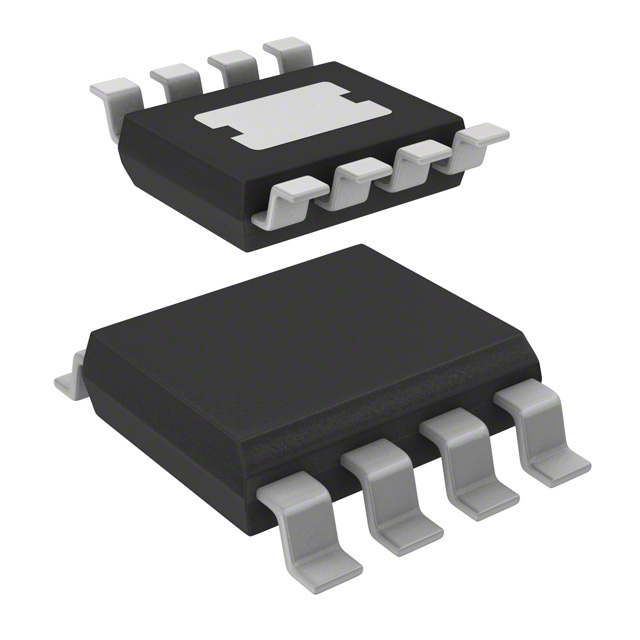
n Thermally Enhanced 8-Lead SO Package
n AEC-Q100 Qualified for Automotive Applications
The LT®8302/LT8302-3 is a monolithic micropower isolated flyback converter. By sampling the isolated output
voltage directly from the primary-side flyback waveform,
the part requires no third winding or opto-isolator for
regulation. The output voltage is programmed with two
external resistors and a third optional temperature compensation resistor. Boundary mode operation provides a
small magnetic solution with excellent load regulation.
Low ripple Burst Mode operation maintains high efficiency
at light load while minimizing the output voltage ripple. A
3.6A, 65V DMOS power switch is integrated along with all
the high voltage circuitry and control logic into a thermally
enhanced 8-lead SO package.
n
APPLICATIONS
Isolated Automotive, Industrial, Medical
Power Supplies
n Isolated Auxiliary/Housekeeping Power Supplies
n
The LT8302/LT8302-3 operates from an input voltage
range of 3V to 42V and delivers up to 18W of isolated
output power. The high level of integration and the use of
boundary and low ripple burst modes result in a simple to
use, low component count, and high efficiency application
solution for isolated power delivery.
All registered trademarks and trademarks are the property of their respective owners. Protected
by U.S. patents, including 5438499, 7463497, 7471522.
TYPICAL APPLICATION
3V to 32VIN/5VOUT Isolated Flyback Converter
3:1
470pF
10µF
39Ω
VIN
EN/UVLO
SW
LT8302/LT8302-3
GND
1µF
INTVCC
9µH
1µH
VOUT–
10mA TO 1.1A (VIN = 5V)
10mA TO 2.0A (VIN = 12V)
10mA TO 2.9A (VIN = 24V)
RREF
115k
85
220µF
154k
RFB
TC
•
•
90
VOUT+
5V
10k
EFFICIENCY (%)
VIN
3V TO 32V
Efficiency vs Load Current
80
75
70
VIN = 5V
VIN = 12V
VIN = 24V
65
8302 TA01a
60
0
0.5
2.0
1.5
1.0
LOAD CURRENT (A)
2.5
3.0
8302 TA01b
Rev. G
Document Feedback
For more information www.analog.com
1
�LT8302/LT8302-3
ABSOLUTE MAXIMUM RATINGS
PIN CONFIGURATION
(Note 1)
SW (Note 2)...............................................................65V
VIN.............................................................................42V
EN/UVLO.....................................................................VIN
RFB.........................................................VIN – 0.5V to VIN
Current Into RFB.....................................................200µA
INTVCC, RREF, TC..........................................................4V
Operating Junction Temperature Range (Notes 3, 4)
LT8302E, LT8302E-3.......................... –40°C to 125°C
LT8302I, LT8302I-3............................ –40°C to 125°C
LT8302J, LT8302J-3........................... –40°C to 150°C
LT8302H, LT8302H-3......................... –40°C to 150°C
LT8302MP.......................................... –55°C to 150°C
Storage Temperature Range................... –65°C to 150°C
Lead Temperature (Soldering, 10 sec).................... 300°C
TOP VIEW
EN/UVLO 1
8
TC
INTVCC 2
7
RREF
6
RFB
5
SW
VIN 3
9
GND
GND 4
S8E PACKAGE
8-LEAD PLASTIC SO
θJA = 33°C/W
EXPOSED PAD (PIN 9) IS GND, MUST BE SOLDERED TO PCB
ORDER INFORMATION
LEAD FREE FINISH
TAPE AND REEL
PART MARKING*
PACKAGE DESCRIPTION
TEMPERATURE RANGE
LT8302ES8E#PBF
LT8302ES8E#TRPBF
8302
8-Lead Plastic SO
–40°C to 125°C
LT8302IS8E#PBF
LT8302IS8E#TRPBF
8302
8-Lead Plastic SO
–40°C to 125°C
LT8302JS8E#PBF
LT8302JS8E#TRPBF
8302
8-Lead Plastic SO
–40°C to 150°C
LT8302HS8E#PBF
LT8302HS8E#TRPBF
8302
8-Lead Plastic SO
–40°C to 150°C
LT8302MPS8E#PBF
LT8302MPS8E#TRPBF
8302
8-Lead Plastic SO
–55°C to 150°C
LT8302ES8E-3#PBF
LT8302ES8E-3#TRPBF
83023
8-Lead Plastic SO
–40°C to 125°C
LT8302IS8E-3#PBF
LT8302IS8E-3#TRPBF
83023
8-Lead Plastic SO
–40°C to 125°C
LT8302JS8E-3#PBF
LT8302JS8E-3#TRPBF
83023
8-Lead Plastic SO
–40°C to 150°C
LT8302HS8E-3#PBF
LT8302HS8E-3#TRPBF
83023
8-Lead Plastic SO
–40°C to 150°C
LT8302ES8E#WPBF
LT8302ES8E#WTRPBF
8302
8-Lead Plastic SO
–40°C to 125°C
LT8302IS8E#WPBF
LT8302IS8E#WTRPBF
8302
8-Lead Plastic SO
–40°C to 125°C
LT8302JS8E#WPBF
LT8302JS8E#WTRPBF
8302
8-Lead Plastic SO
–40°C to 150°C
LT8302HS8E#WPBF
LT8302HS8E#WTRPBF
8302
8-Lead Plastic SO
–40°C to 150°C
LT8302ES8E-3#WPBF
LT8302ES8E-3#WTRPBF
83023
8-Lead Plastic SO
–40°C to 125°C
LT8302IS8E-3#WPBF
LT8302IS8E-3#WTRPBF
83023
8-Lead Plastic SO
–40°C to 125°C
LT8302JS8E-3#WPBF
LT8302JS8E-3#WTRPBF
83023
8-Lead Plastic SO
–40°C to 150°C
LT8302HS8E-3#WPBF
LT8302HS8E-3#WTRPBF
83023
8-Lead Plastic SO
–40°C to 150°C
AUTOMOTIVE PRODUCTS**
Contact the factory for parts specified with wider operating temperature ranges. *The temperature grade is identified by a label on the shipping container.
Tape and reel specifications. Some packages are available in 500 unit reels through designated sales channels with #TRMPBF suffix.
**Versions of this part are available with controlled manufacturing to support the quality and reliability requirements of automotive applications. These
models are designated with a #W suffix. Only the automotive grade products shown are available for use in automotive applications. Contact your
local Analog Devices account representative for specific product ordering information and to obtain the specific Automotive Reliability reports for
these models.
2
Rev. G
For more information www.analog.com
�LT8302/LT8302-3
ELECTRICAL CHARACTERISTICS
The l denotes the specifications which apply over the full operating
temperature range, otherwise specifications are at TA = 25°C. VIN = 5V, VEN/UVLO = VIN, CINTVCC = 1µF to GND, unless otherwise noted.
SYMBOL
PARAMETER
VIN
VIN Voltage Range
IQ
VIN Quiescent Current
CONDITIONS
MIN
l
TYP
3
VEN/UVLO = 0.2V
VEN/UVLO = 1.1V
Sleep Mode (Switch Off)
Active Mode (Switch On)
0.5
53
106
380
MAX
UNIT
42
V
2
µA
µA
µA
µA
EN/UVLO Shutdown Threshold
For Lowest Off IQ
l
0.2
0.75
EN/UVLO Enable Threshold
Falling (E, I, H, MP Grades)
l
1.178
1.214
1.250
V
EN/UVLO Enable Threshold
Falling (J Grade Only)
l
1.160
1.214
1.268
V
EN/UVLO Enable Hysteresis
V
14
mV
IHYS
EN/UVLO Hysteresis Current
VEN/UVLO = 0.3V
VEN/UVLO = 1.1V
VEN/UVLO = 1.3V
–0.1
2.3
–0.1
0
2.5
0
0.1
2.7
0.1
µA
µA
µA
VINTVCC
INTVCC Regulation Voltage
IINTVCC = 0mA to 10mA
2.85
3
3.1
V
INTVCC Current Limit
VINTVCC = 2.8V
10
13
20
mA
INTVCC UVLO Threshold
Falling
2.39
2.47
2.55
IRFB = 75µA to 125µA
–50
IINTVCC
INTVCC UVLO Hysteresis
(RFB – VIN) Voltage
105
RREF Regulation Voltage
RREF Regulation Voltage Line Regulation
l
3V ≤ VIN ≤ 42V
0.98
–0.01
V
mV
50
mV
1.00
1.02
V
0
0.01
%/V
VTC
TC Pin Voltage
1.00
ITC
TC Pin Current
fMIN
Minimum Switching Frequency
tON(MIN)
Minimum Switch-On Time
tOFF(MAX)
Maximum Switch-Off Time
ISW(MAX)
Maximum Switch Current Limit
3.6
4.5
5.4
A
ISW(MIN)
Minimum Switch Current Limit
0.70
0.87
1.04
A
VTC = 1.2V (LT8302)
VTC = 1.2V (LT8302-3)
VTC = 0.8V
V
12
7
15
10
–200
18
13
µA
µA
µA
11.3
12
12.7
kHz
160
Backup Timer
170
RDS(ON)
Switch On-Resistance
ISW = 1.5A
80
ILKG
Switch Leakage Current
VSW = 65V
0.1
tSS
Soft-Start Timer
11
Note 1: Stresses beyond those listed under Absolute Maximum Ratings
may cause permanent damage to the device. Exposure to any Absolute
Maximum Rating condition for extended periods may affect device
reliability and lifetime.
Note 2: The SW pin is rated to 65V for transients. Depending on the
leakage inductance voltage spike, operating waveforms of the SW pin
should be derated to keep the flyback voltage spike below 65V as shown
in Figure 5.
Note 3: The LT8302E/LT8302E-3 is guaranteed to meet performance
specifications from 0°C to 125°C junction temperature. Specifications
over the –40°C to 125°C operating junction temperature range are
assured by design, characterization and correlation with statistical process
ns
µs
mΩ
0.5
µA
ms
controls. The LT8302I/LT8302I-3 is guaranteed over the full –40°C to
125°C operating junction temperature range. The LT8302J/LT8302J-3
and LT8302H/LT8302H-3 are guaranteed over the full –40°C to 150°C
operating junction temperature range. The LT8302MP is guaranteed
over the full –55°C to 150°C operating junction temperature range. High
junction temperatures degrade operating lifetimes. Operating lifetime is
derated at junction temperature greater than 125°C.
Note 4: The LT8302/LT8302-3 includes overtemperature protection that
is intended to protect the devices during momentary overload conditions.
Junction temperature will exceed 150°C when overtemperature protection
is active. Continuous operation above the specified maximum operating
junction temperature may impair device reliability.
Rev. G
For more information www.analog.com
3
�LT8302/LT8302-3
TYPICAL PERFORMANCE CHARACTERISTICS
Output Load and Line Regulation
5.3
5.00
4.95
VIN = 5V
VIN = 12V
VIN = 24V
4.80
0.5
0
1.0
2.0
1.5
LOAD CURRENT (A)
2.5
5.1
RTC = 115k
5.0
RTC = OPEN
4.9
4.7
–50 –25
0
VSW
20V/DIV
VOUT
50mV/DIV
VOUT
50mV/DIV
8302 G04
8302 G05
VIN Quiescent Current,
Active Mode
TJ = 150°C
IQ (µA)
110
TJ = –55°C
30
VIN (V)
40
50
80
0
10
20
30
VIN (V)
40
50
8302 G08
8302 G07
4
TJ = 25°C
380
TJ = –55°C
360
340
90
20
TJ = 150°C
400
TJ = 25°C
100
10
8302 G06
20µs/DIV
FRONT PAGE APPLICATION
VIN = 12V
IOUT = 10mA
120
0
3.0
420
130
IQ (µA)
IQ (µA)
0
2.5
VOUT
50mV/DIV
140
TJ = 150°C
TJ = 25°C
TJ = –55°C
2
2.0
1.0
1.5
LOAD CURRENT (A)
Burst Mode Waveforms
VIN Quiescent Current,
Sleep Mode
4
0.5
VSW
20V/DIV
2µs/DIV
FRONT PAGE APPLICATION
VIN = 12V
IOUT = 0.5A
VIN Shutdown Current
6
0
8302 G03
Discontinuous Mode Waveforms
VSW
20V/DIV
8
VIN = 5V
VIN = 12V
VIN = 24V
8302 G02
Boundary Mode Waveforms
10
200
0
25 50 75 100 125 150
TEMPERATURE (°C)
8302 G01
2µs/DIV
FRONT PAGE APPLICATION
VIN = 12V
IOUT = 2A
300
100
4.8
3.0
FRONT PAGE APPLICATION
400
FREQUENCY (kHz)
5.05
500
FRONT PAGE APPLICATION
VIN = 12V
IOUT = 1A
5.2
5.10
OUTPUT VOLTAGE (V)
OUTPUT VOLTAGE (V)
5.15
4.85
Switching Frequency
vs Load Current
Output Temperature Variation
5.20
4.90
TA = 25°C, unless otherwise noted.
320
0
10
20
30
VIN (V)
40
50
8302 G09
Rev. G
For more information www.analog.com
�LT8302/LT8302-3
TYPICAL PERFORMANCE CHARACTERISTICS
EN/UVLO Enable Threshold
TA = 25°C, unless otherwise noted.
EN/UVLO Hysteresis Current
1.240
INTVCC Voltage vs Temperature
5
RISING
IHYST (µA)
VEN/UVLO (V)
1.225
1.220
FALLING
1.215
3.05
4
1.230
1.210
3.00
3
VINTVCC (V)
1.235
3.10
2
1
0
IINTVCC = 10mA
2.85
0
–50 –25
25 50 75 100 125 150
TEMPERATURE (°C)
2.95
2.90
1.205
1.200
–50 –25
IINTVCC = 0mA
0
2.80
–50 –25
25 50
75 100 125 150
TEMPERATURE (°C)
8302 G10
0
25 50 75 100 125 150
TEMPERATURE (°C)
8302 G12
8302 G11
INTVCC Voltage vs VIN
INTVCC UVLO Threshold
3.10
2.8
3.05
2.7
(RFB-VIN) Voltage
40
30
IRFB = 125µA
2.6
IINTVCC = 0mA
2.95
VINTVCC (V)
VINTVCC (V)
3.00
IINTVCC = 10mA
RISING
2.5
2.90
2.4
2.85
2.3
VOLTAGE (mV)
20
FALLING
10
IRFB = 100µA
0
–10
–20
2.80
5
10
15
20
25 30
VIN (V)
35
40
–30
2.2
–50 –25
45
0
RREF Line Regulation
TC Pin Voltage
1.008
1.006
1.006
1.004
1.004
1.002
1.002
1.5
1.4
1.3
1.2
VTC (V)
VRREF (V)
VRREF (V)
1.008
1.000
0.998
0.998
0.996
0.996
0.994
0.994
0.992
0.992
0
25 50 75 100 125 150
TEMPERATURE (°C)
25 50 75 100 125 150
TEMPERATURE (°C)
8302 G15
1.010
1.000
0
8302 G14
RREF Regulation Voltage
0.990
–50 –25
–40
–50 –25
25 50 75 100 125 150
TEMPERATURE (°C)
8302 G13
1.010
IRFB = 75µA
0.990
1.1
1.0
0.9
0.8
0
10
20
30
VIN (V)
40
8302 G16
50
8302 G17
0.7
–50 –25
0
25 50 75 100 125 150
TEMPERATURE (°C)
8302 G18
Rev. G
For more information www.analog.com
5
�LT8302/LT8302-3
TYPICAL PERFORMANCE CHARACTERISTICS
Switch Current Limit
5
160
4
120
3
80
40
MAXIMUM CURRENT LIMIT
0
MINIMUM CURRENT LIMIT
0
–50 –25
25 50
75 100 125 150
TEMPERATURE (°C)
0
Minimum Switching Frequency
25 50
75 100 125 150
TEMPERATURE (°C)
400
300
300
200
0
–50 –25
200
100
0
25 50 75 100 125 150
TEMPERATURE (°C)
8302 G22
6
25 50
75 100 125 150
TEMPERATURE (°C)
Minimum Switch-Off Time
400
100
0
0
8302 G21
TIME (ns)
TIME (ns)
FREQUENCY (kHz)
0
–50 –25
0
–50 –25
Minimum Switch-On Time
16
4
200
8302 G20
20
8
300
100
25 50
75 100 125 150
TEMPERATURE (°C)
8302 G19
12
400
2
1
0
–50 –25
Maximum Switching Frequency
500
FREQUENCY (kHz)
200
ISW (A)
RESISTANCE (mΩ)
RDS(ON)
TA = 25°C, unless otherwise noted.
8302 G23
0
–50 –25
0
25 50 75 100 125 150
TEMPERATURE (°C)
8302 G24
Rev. G
For more information www.analog.com
�LT8302/LT8302-3
PIN FUNCTIONS
EN/UVLO (Pin 1): Enable/Undervoltage Lockout. The
EN/UVLO pin is used to enable the LT8302/LT8302-3.
Pull the pin below 0.3V to shut down the LT8302/LT83023. This pin has an accurate 1.214V threshold and can
be used to program a VIN undervoltage lockout (UVLO)
threshold using a resistor divider from VIN to ground. A
2.5µA current hysteresis allows the programming of VIN
UVLO hysteresis. If neither function is used, tie this pin
directly to VIN.
SW (Pin 5): Drain of the Internal DMOS Power Switch.
Minimize trace area at this pin to reduce EMI and voltage
spikes.
INTVCC (Pin 2): Internal 3V Linear Regulator Output. The
INTVCC pin is supplied from VIN and powers the internal control circuitry and gate driver. Do not overdrive the
INTVCC pin with any external supply, such as a third winding supply. Locally bypass this pin to ground with a minimum 1µF ceramic capacitor.
RREF (Pin 7): Input Pin for External Ground Referred
Reference Resistor. The resistor at this pin should be in
the range of 10k, but for convenience in selecting a resistor divider ratio, the value may range from 9.09k to 11.0k.
VIN (Pin 3): Input Supply. The VIN pin supplies current to
the internal circuitry and serves as a reference voltage for
the feedback circuitry connected to the RFB pin. Locally
bypass this pin to ground with a capacitor.
GND (Pin 4, Exposed Pad Pin 9): Ground. The exposed
pad provides both electrical contact to ground and good
thermal contact to the printed circuit board. Solder the
exposed pad directly to the ground plane.
RFB (Pin 6): Input Pin for External Feedback Resistor.
Connect a resistor from this pin to the transformer primary SW pin. The ratio of the RFB resistor to the RREF
resistor, times the internal voltage reference, determines
the output voltage (plus the effect of any non-unity transformer turns ratio). Minimize trace area at this pin.
TC (Pin 8): Output Voltage Temperature Compensation.
The voltage at this pin is proportional to absolute temperature (PTAT) with temperature coefficient equal to
3.35mV/°K, i.e., equal to 1V at room temperature 25°C.
The TC pin voltage can be used to estimate the LT8302/
LT8302-3 junction temperature. Connect a resistor from
this pin to the RREF pin to compensate the output diode
temperature coefficient.
Rev. G
For more information www.analog.com
7
�LT8302/LT8302-3
BLOCK DIAGRAM
T1
N:1
VIN
CIN
L1A
RFB
3
2
6
1:4
M3
M2
REN2
OSCILLATOR
–
1.214V
+
1V
–
A1
VOUT–
START-UP,
REFERENCE,
CONTROL
BOUNDARY
DETECTOR
+
1
EN/UVLO
COUT
SW
25µA
REN1
L1B
VIN
LDO
CINTVCC
•
VOUT+
5
RFB
VIN
INTVCC
•
DOUT
INTVCC
–
gm
+
S
A3
R
Q
M1
DRIVER
2.5µA
PTAT
VOLTAGE
M4
+
A2
RSENSE
–
RREF
7
TC
GND
4, EXPOSED PAD PIN 9
8
RTC
8302 BD
RREF
8
Rev. G
For more information www.analog.com
�LT8302/LT8302-3
OPERATION
The LT8302/LT8302-3 is a current mode switching regulator IC designed specially for the isolated flyback topology.
The key problem in isolated topologies is how to communicate the output voltage information from the isolated
secondary side of the transformer to the primary side
for regulation. Historically, opto-isolators or extra transformer windings communicate this information across
the isolation boundary. Opto-isolator circuits waste output
power, and the extra components increase the cost and
physical size of the power supply. Opto-isolators can also
cause system issues due to limited dynamic response,
nonlinearity, unit-to-unit variation and aging over lifetime. Circuits employing extra transformer windings also
exhibit deficiencies, as using an extra winding adds to
the transformer’s physical size and cost, and dynamic
response is often mediocre.
The LT8302/LT8302-3 samples the isolated output voltage
through the primary-side flyback pulse waveform. In this
manner, neither opto-isolator nor extra transformer winding is required for regulation. Since the LT8302/LT8302-3
operates in either boundary conduction mode or discontinuous conduction mode, the output voltage is always
sampled on the SW pin when the secondary current is
zero. This method improves load regulation without the
need of external load compensation components.
The LT8302/LT8302-3 is a simple to use micropower isolated flyback converter housed in a thermally enhanced
8-lead SO package. The output voltage is programmed
with two external resistors. An optional TC resistor
provides easy output diode temperature compensation.
By integrating the loop compensation and soft-start
inside, the part reduces the number of external components. As shown in the Block Diagram, many of the blocks
are similar to those found in traditional switching regulators including reference, regulators, oscillator, logic,
current amplifier, current comparator, driver, and power
switch. The novel sections include a flyback pulse sense
circuit, a sample-and-hold error amplifier, and a boundary
mode detector, as well as the additional logic for boundary
conduction mode, discontinuous conduction mode, and
low ripple Burst Mode operation.
Quasi-Resonant Boundary Mode Operation
The LT8302/LT8302-3 features quasi-resonant boundary conduction mode operation at heavy load, where
the chip turns on the primary power switch when the
secondary current is zero and the SW rings to its valley.
Boundary conduction mode is a variable frequency, variable peak-current switching scheme. The power switch
turns on and the transformer primary current increases
until an internally controlled peak current limit. After the
power switch turns off, the voltage on the SW pin rises to
the output voltage multiplied by the primary-to-secondary
transformer turns ratio plus the input voltage. When the
secondary current through the output diode falls to zero,
the SW pin voltage collapses and rings around VIN. A
boundary mode detector senses this event and turns the
power switch back on at its valley.
Rev. G
For more information www.analog.com
9
�LT8302/LT8302-3
OPERATION
Boundary conduction mode returns the secondary current
to zero every cycle, so parasitic resistive voltage drops
do not cause load regulation errors. Boundary conduction mode also allows the use of smaller transformers
compared to continuous conduction mode and does not
exhibit subharmonic oscillation.
Discontinuous Conduction Mode Operation
As the load gets lighter, boundary conduction mode
increases the switching frequency and decreases the
switch peak current at the same ratio. Running at a higher
switching frequency up to several MHz increases switching and gate charge losses. To avoid this scenario, the
LT8302/LT8302-3 has an additional internal oscillator,
which clamps the maximum switching frequency to be
less than 380kHz. Once the switching frequency hits the
internal frequency clamp, the part starts to delay the switch
turn-on and operates in discontinuous conduction mode.
Low Ripple Burst Mode Operation
Unlike traditional flyback converters, the LT8302/
LT8302-3 has to turn on and off at least for a minimum
amount of time and with a minimum frequency to allow
accurate sampling of the output voltage. The inherent
10
minimum switch current limit and minimum switch-off
time are necessary to guarantee the correct operation of
specific applications.
As the load gets very light, the LT8302/LT8302-3 starts to
fold back the switching frequency while keeping the minimum switch current limit. So the load current is able to
decrease while still allowing minimum switch-off time for
the sample-and-hold error amplifier. Meanwhile, the part
switches between sleep mode and active mode, thereby
reducing the effective quiescent current to improve light
load efficiency. In this condition, the LT8302/LT8302-3
runs in low ripple Burst Mode operation. The typical
12kHz minimum switching frequency determines how
often the output voltage is sampled and also the minimum load requirement.
Difference Between LT8302 and LT8302-3
The difference between LT8302 and LT8302-3 is
the boundary detection method. The LT8302 is using the
dv/dt slope on RREF pin, while the LT8302-3 is using the
voltage level on RREF pin. For good transformers with
low leakage inductance, both the LT8302 and LT8302-3
are behaving the same. The LT8302-3 is recommended
for multiple-winding output applications due to its lower
sensitivity to the noise on RREF pin.
Rev. G
For more information www.analog.com
�LT8302/LT8302-3
APPLICATIONS INFORMATION
Output Voltage
The RFB and RREF resistors as depicted in the Block
Diagram are external resistors used to program the output voltage. The LT8302/LT8302-3 operates similar to
traditional current mode switchers, except in the use of a
unique flyback pulse sense circuit and a sample-and-hold
error amplifier, which sample and therefore regulate the
isolated output voltage from the flyback pulse.
Operation is as follows: when the power switch M1 turns
off, the SW pin voltage rises above the VIN supply. The
amplitude of the flyback pulse, i.e., the difference between
the SW pin voltage and VIN supply, is given as:
VFLBK = (VOUT + VF + ISEC • ESR) • NPS
VF = Output diode forward voltage
ISEC = Transformer secondary current
ESR = Total impedance of secondary circuit
NPS = Transformer effective primary-to-secondary
turns ratio
The flyback voltage is then converted to a current, IRFB,
by the RFB resistor and the flyback pulse sense circuit
(M2 and M3). This current, IRFB, also flows through the
RREF resistor to generate a ground-referred voltage. The
resulting voltage feeds to the inverting input of the sample-and-hold error amplifier. Since the sample-and-hold
error amplifier samples the voltage when the secondary
current is zero, the (ISEC • ESR) term in the VFLBK equation
can be assumed to be zero.
The internal reference voltage, VREF, 1.00V, feeds to the
noninverting input of the sample-and-hold error amplifier.
The relatively high gain in the overall loop causes the
voltage at the RREF pin to be nearly equal to the internal
reference voltage VREF. The resulting relationship between
VFLBK and VREF can be expressed as:
⎛ VFLBK ⎞
⎜
⎟ •RREF = VREF or
⎝ RFB ⎠
⎛R ⎞
VFLBK = VREF • ⎜ FB ⎟
⎝ RREF ⎠
VREF = Internal reference voltage 1.00V
Combination with the previous VFLBK equation yields an
equation for VOUT, in terms of the RFB and RREF resistors,
transformer turns ratio, and diode forward voltage:
⎛R ⎞ ⎛ 1 ⎞
VOUT = VREF • ⎜ FB ⎟ • ⎜
⎟ – VF
RREF ⎠ ⎝ NPS ⎠
⎝
Output Temperature Compensation
The first term in the VOUT equation does not have temperature dependence, but the output diode forward
voltage, VF, has a significant negative temperature coefficient (–1mV/°C to –2mV/°C). Such a negative temperature coefficient produces approximately 200mV to
300mV voltage variation on the output voltage across
temperature.
For higher voltage outputs, such as 12V and 24V, the
output diode temperature coefficient has a negligible
effect on the output voltage regulation. For lower voltage
outputs, such as 3.3V and 5V, however, the output diode
temperature coefficient does count for an extra 2% to 5%
output voltage regulation.
The LT8302/LT8302-3 junction temperature usually tracks
the output diode junction temperature to the first order.
To compensate the negative temperature coefficient of the
output diode, a resistor, RTC, connected between the TC
and RREF pins generates a proportional-to-absolute-temperature (PTAT) current. The PTAT current is zero at 25°C,
flows into the RREF pin at hot temperature, and flows out
of the RREF pin at cold temperature. With the RTC resistor
in place, the output voltage equation is revised as follows:
VOUT = VREF •
RFB
1
•
– VF (TO) – ( VTC / T ) •
RREF
NPS
( T –TO) •
RFB
1
•
– ( VF / T ) • ( T–TO)
R TC
NPS
TO=Room temperature 25°C
(
(
VF / T ) = Output diode forward voltage
temperature coefficient
VTC / T ) = 3.35mV/ °C
Rev. G
For more information www.analog.com
11
�LT8302/LT8302-3
APPLICATIONS INFORMATION
To cancel the output diode temperature coefficient, the
following two equations should be satisfied:
VOUT = VREF •
(
VTC / T) •
RFB
1
•
– VF (TO)
RREF
NPS
RFB
1
•
= – ( VF / T )
R TC
NPS
Selecting Actual RREF, RFB, RTC Resistor Values
The LT8302/LT8302-3 uses a unique sampling scheme
to regulate the isolated output voltage. Due to the sampling nature, the scheme contains repeatable delays and
error sources, which will affect the output voltage and
force a re-evaluation of the RFB and RTC resistor values.
Therefore, a simple 2-step sequential process is recommended for selecting resistor values.
Rearrangement of the expression for VOUT in the previous
sections yields the starting value for RFB:
RFB =
(
RREF •NPS • VOUT + VF (TO)
VREF
)
VOUT = Output voltage
VF (TO) = Output diode forward voltage at 25°C = ~0.3V
NPS = Transformer effective primary-to-secondary
turns ratio
The equation shows that the RFB resistor value is independent of the RTC resistor value. Any RTC resistor connected
between the TC and RREF pins has no effect on the output
voltage setting at 25°C because the TC pin voltage is equal
to the RREF regulation voltage at 25°C.
The RREF resistor value should be approximately 10k
because the LT8302/LT8302-3 is trimmed and specified
using this value. If the RREF resistor value varies considerably from 10k, additional errors will result. However, a
variation in RREF up to 10% is acceptable. This yields a
bit of freedom in selecting standard 1% resistor values
to yield nominal RFB/RREF ratios.
12
First, build and power up the application with the starting
RREF, RFB values (no RTC resistor yet) and other components connected, and measure the regulated output
voltage, VOUT(MEAS). The new RFB value can be adjusted
to:
RFB(NEW) =
VOUT
VOUT(MEAS)
•RFB
Second, with a new RFB resistor value selected, the output
diode temperature coefficient in the application can be
tested to determine the RTC value. Still without the RTC
resistor, the VOUT should be measured over temperature
at a desired target output load. It is very important for this
evaluation that uniform temperature be applied to both the
output diode and the LT8302/LT8302-3. If freeze spray or
a heat gun is used, there can be a significant mismatch
in temperature between the two devices that causes significant error. Attempting to extrapolate the data from a
diode data sheet is another option if there is no method
to apply uniform heating or cooling such as an oven. With
at least two data points spreading across the operating
temperature range, the output diode temperature coefficient can be determined by:
– (δVF /δT ) =
VOUT ( T1) – VOUT ( T2)
T1– T2
Using the measured output diode temperature coefficient,
an exact RTC value can be selected with the following
equation:
R TC =
(δVTC /δT) • ⎛⎜ RFB ⎞⎟
– (δVF /δT ) ⎝ NPS ⎠
Once the RREF, RFB, and RTC values are selected, the regulation accuracy from board to board for a given application will be very consistent, typically under ±5% when
including device variation of all the components in the
system (assuming resistor tolerances and transformer
windings matching within ±1%). However, if the transformer or the output diode is changed, or the layout is
dramatically altered, there may be some change in VOUT.
Rev. G
For more information www.analog.com
�LT8302/LT8302-3
APPLICATIONS INFORMATION
Output Power
A flyback converter has a complicated relationship between
the input and output currents compared to a buck or a
boost converter. A boost converter has a relatively constant
maximum input current regardless of input voltage and a
buck converter has a relatively constant maximum output current regardless of input voltage. This is due to the
continuous non-switching behavior of the two currents. A
flyback converter has both discontinuous input and output currents which make it similar to a nonisolated buckboost converter. The duty cycle will affect the input and
output currents, making it hard to predict output power. In
addition, the winding ratio can be changed to multiply the
output current at the expense of a higher switch voltage.
5V, 12V, and 24V. The maximum output power curve is
the calculated output power if the switch voltage is 50V
during the switch-off time. 15V of margin is left for leakage inductance voltage spike. To achieve this power level
at a given input, a winding ratio value must be calculated
to stress the switch to 50V, resulting in some odd ratio
values. The curves below the maximum output power
curve are examples of common winding ratio values and
the amount of output power at given input voltages.
One design example would be a 5V output converter with
a minimum input voltage of 8V and a maximum input
voltage of 32V. A three-to-one winding ratio fits this
design example perfectly and outputs equal to 15.3W at
32V but lowers to 7.7W at 8V.
The graphs in Figure 1 to Figure 4 show the typical maximum output power possible for the output voltages 3.3V,
20
20
MAXIMUM
OUTPUT POWER
15
N = 6:1
OUTPUT POWER (W)
OUTPUT POWER (W)
MAXIMUM
OUTPUT POWER
N = 4:1
N = 3:1
10
N = 2:1
5
0
0
20
10
30
INPUT VOLTAGE (V)
15
N = 3:2
N = 1:2
5
OUTPUT POWER (W)
OUTPUT POWER (W)
N = 4:1
N = 2:1
10
N = 1:1
5
0
10
20
INPUT VOLTAGE (V)
30
30
40
8302 F03
Figure 3. Output Power for 12V Output
20
N = 3:1
20
10
INPUT VOLTAGE (V)
MAXIMUM
OUTPUT POWER
15
0
0
8302 F01
Figure 1. Output Power for 3.3V Output
20
N = 1:1
10
0
40
N = 2:1
MAXIMUM
OUTPUT POWER
N = 1:1
15
N = 2:3
N = 1:2
10
N = 1:3
5
0
40
0
10
20
INPUT VOLTAGE (V)
8302 F02
Figure 2. Output Power for 5V Output
30
40
8302 F04
Figure 4. Output Power for 24V Output
Rev. G
For more information www.analog.com
13
�LT8302/LT8302-3
APPLICATIONS INFORMATION
The equations below calculate output power:
the power switch shorter than approximately 160ns. This
minimum switch-on time is mainly for leading-edge blanking the initial switch turn-on current spike. If the inductor
current exceeds the desired current limit during that time,
oscillation may occur at the output as the current control
loop will lose its ability to regulate. Therefore, the following
equation relating to maximum input voltage must also be
followed in selecting primary-side magnetizing inductance:
POUT = η • VIN • D • ISW(MAX) • 0.5
η = Efficiency = ~85%
D=Duty Cycle =
( VOUT + VF ) •NPS
( VOUT + VF ) •NPS + VIN
ISW(MAX) = Maximum switch current limit = 3.6A (MIN)
Primary Inductance Requirement
The LT8302/LT8302-3 obtains output voltage information
from the reflected output voltage on the SW pin. The conduction of secondary current reflects the output voltage on
the primary SW pin. The sample-and-hold error amplifier
needs a minimum 350ns to settle and sample the reflected
output voltage. In order to ensure proper sampling, the
secondary winding needs to conduct current for a minimum of 350ns. The following equation gives the minimum
value for primary-side magnetizing inductance:
LPRI ≥
tON(MIN) • VIN(MAX)
ISW(MIN)
tON(MIN) = Minimum switch-on time = 160ns (TYP)
In general, choose a transformer with its primary magnetizing inductance about 40% to 60% larger than the
minimum values calculated above. A transformer with
much larger inductance will have a bigger physical size
and may cause instability at light load.
Selecting a Transformer
Transformer specification and design is perhaps the most
critical part of successfully applying the LT8302/LT83023. In addition to the usual list of guidelines dealing with
high frequency isolated power supply transformer design,
the following information should be carefully considered.
tOFF(MIN) •NPS • ( VOUT + VF )
LPRI ≥
ISW(MIN)
tOFF(MIN) = Minimum switch-off time = 350ns (TYP)
ISW(MIN) = Minimum switch current limit = 0.87A (TYP)
Analog Devices has worked with several leading magnetic
component manufacturers to produce pre-designed flyback transformers for use with the LT8302/LT8302-3.
Table 1 shows the details of these transformers.
In addition to the primary inductance requirement for the
minimum switch-off time, the LT8302/LT8302-3 has minimum switch-on time that prevents the chip from turning on
Table 1. Predesigned Transformers–Typical Specifications
TRANSFORMER
PART NUMBER
RSEC
(mΩ) VENDOR
TARGET APPLICATION
VIN (V)
VOUT (V)
IOUT (A)
DIMENSIONS
(W × L × H) (mm)
LPRI
(µH)
LLKG
(µH)
NP:NS
RPRI
(mΩ)
750311625
17.75 × 13.46 × 12.70
9
0.35
4:1
43
6
Wurth Elektronik
8 to 32
3.3
2.1
750311564
17.75 × 13.46 × 12.70
9
0.12
3:1
36
7
Wurth Elektronik
8 to 32
5
1.5
750313441
15.24 × 13.34 x 11.43
9
0.6
2:1
75
18
Wurth Elektronik
8 to 32
5
1.3
750311624
17.75 × 13.46 × 12.70
9
0.18
3:2
34
21
Wurth Elektronik
8 to 32
8
0.9
12387-TO79
15.5 × 12.5 × 11.5
9
0.5
1:1:1
55
90
Sumida
8 to 36
±12
0.3
750313445
15.24 × 13.34 × 11.43
9
0.25
1:2
85
190
Wurth Elektronik
8 to 36
24
0.3
750313457
15.24 × 13.34 × 11.43
9
0.25
1:4
85
770
Wurth Elektronik
8 to 36
48
0.15
750313460
15.24 × 13.34 × 11.43
12
0.7
4:1
85
11
Wurth Elektronik
4 to 18
5
0.9
750311342
15.24 × 13.34 × 11.43
15
0.44
2:1
85
22
Wurth Elektronik
4 to 18
12
0.4
750313439
15.24 × 13.34 × 11.43
12
0.6
2:1
115
28
Wurth Elektronik
18 to 42
3.3
2.1
750313442
15.24 × 13.34 × 11.43
12
0.75
3:2
150
53
Wurth Elektronik
18 to 42
5
1.6
14
Rev. G
For more information www.analog.com
�LT8302/LT8302-3
APPLICATIONS INFORMATION
Turns Ratio
Note that when choosing an RFB/RREF resistor ratio to set
output voltage, the user has relative freedom in selecting
a transformer turns ratio to suit a given application. In
contrast, the use of simple ratios of small integers, e.g.,
3:1, 2:1, 1:1, etc., provides more freedom in settling total
turns and mutual inductance.
Typically, choose the transformer turns ratio to maximize
available output power. For low output voltages (3.3V
or 5V), a N:1 turns ratio can be used with multiple primary windings relative to the secondary to maximize the
transformer’s current gain (and output power). However,
remember that the SW pin sees a voltage that is equal
to the maximum input supply voltage plus the output
voltage multiplied by the turns ratio. In addition, leakage
inductance will cause a voltage spike (VLEAKAGE) on top of
this reflected voltage. This total quantity needs to remain
below the 65V absolute maximum rating of the SW pin to
prevent breakdown of the internal power switch. Together
these conditions place an upper limit on the turns ratio,
NPS, for a given application. Choose a turns ratio low
enough to ensure
NPS <
65V – VIN(MAX) – VLEAKAGE
VOUT + VF
For larger N:1 values, choose a transformer with a larger
physical size to deliver additional current. In addition,
choose a large enough inductance value to ensure that
the switch-off time is long enough to accurately sample
the output voltage.
For lower output power levels, choose a 1:1 or 1:N transformer for the absolute smallest transformer size. A 1:N
transformer will minimize the magnetizing inductance
(and minimize size), but will also limit the available output
power. A higher 1:N turns ratio makes it possible to have
very high output voltages without exceeding the breakdown voltage of the internal power switch.
The turns ratio is an important element in the isolated
feedback scheme, and directly affects the output voltage
accuracy. Make sure the transformer manufacturer specifies turns ratio accuracy within ±1%.
Saturation Current
The current in the transformer windings should not exceed
its rated saturation current. Energy injected once the core
is saturated will not be transferred to the secondary and
will instead be dissipated in the core. When designing
custom transformers to be used with the LT8302/LT83023, the saturation current should always be specified by
the transformer manufacturers.
Winding Resistance
Resistance in either the primary or secondary windings
will reduce overall power efficiency. Good output voltage
regulation will be maintained independent of winding
resistance due to the boundary/discontinuous conduction
mode operation of the LT8302/LT8302-3.
Leakage Inductance and Snubbers
Transformer leakage inductance on either the primary
or secondary causes a voltage spike to appear on the
primary after the power switch turns off. This spike is
increasingly prominent at higher load currents where
more stored energy must be dissipated. It is very important to minimize transformer leakage inductance.
When designing an application, adequate margin should
be kept for the worst-case leakage voltage spikes even
under overload conditions. In most cases shown in
Figure 5, the reflected output voltage on the primary plus
VIN should be kept below 50V. This leaves at least 15V
margin for the leakage spike across line and load conditions. A larger voltage margin will be required for poorly
wound transformers or for excessive leakage inductance.
Rev. G
For more information www.analog.com
15
�LT8302/LT8302-3
APPLICATIONS INFORMATION
VSW(MAX)
The PDS835L (8A, 35V diode) from Diodes Inc. is chosen.
VSW(MAX) = VIN(MAX) + VZENNER(MAX)
Step 4: Choose the output capacitor.
Example:
The output capacitor should be chosen to minimize the
output voltage ripple while considering the increase in size
VREVERSE > 60V
A 100V, 1A diode from Diodes Inc. (DFLS1100) is chosen.
Rev. G
For more information www.analog.com
19
�LT8302/LT8302-3
APPLICATIONS INFORMATION
Step 6: Select the RREF and RFB resistors.
Example:
Use the following equation to calculate the starting values
for RREF and RFB:
RFB =
(
– (δVF /δT ) =
)
RREF • NPS • VOUT + VF ( TO)
VREF
R TC =
RREF = 10k
5.189V – 5.041V
=1.48mV / °C
100°C – (0°C)
3.35mV/°C ⎛ 154 ⎞
•⎜
⎟ =115k
1.48mV/°C ⎝ 3 ⎠
Step 9: Select the EN/UVLO resistors.
Example:
Determine the amount of hysteresis required and calculate R1 resistor value:
10k • 3 • (5V+0.3V )
RFB =
=159k
1.00V
VIN(HYS) = 2.5µA • R1
For 1% standard values, a 158k resistor is chosen.
Example:
Step 7: Adjust RFB resistor based on output voltage.
Choose 2V of hysteresis, R1 = 806k
Build and power up the application with application components and measure the regulated output voltage. Adjust
RFB resistor based on the measured output voltage:
Determine the UVLO thresholds and calculate R2 resistor
value:
RFB(NEW) =
VOUT
VOUT(MEASURED)
•RFB
Set VIN UVLO rising threshold to 7.5V:
5V
•158k =154k
5.14V
Step 8: Select RTC resistor based on output voltage temperature variation.
Measure output voltage in a controlled temperature environment like an oven to determine the output temperature
coefficient. Measure output voltage at a consistent load
current and input voltage, across the operating temperature range.
Calculate the temperature coefficient of VF:
V ( T1) – VOUT ( T2)
– (δVF /δT ) = OUT
T1– T2
R TC =
20
3.35mV/°C ⎛ RFB ⎞
•⎜
⎟
– (δVF /δT ) ⎝ NPS ⎠
1.228V • (R1+ R2)
+ 2.5µA • R1
R2
Example:
Example:
RFB =
VIN(UVLO+) =
R2 = 232k
VIN(UVLO+) = 7.5V
VIN(UNLO–) = 5.5V
Step 10: Ensure minimum load.
The theoretical minimum load can be approximately estimated as:
ILOAD(MIN) =
2
9µH • ( 1.04A ) • 12.7kHz
=12.4mA
2 • 5V
Remember to check the minimum load requirement in
real application. The minimum load occurs at the point
where the output voltage begins to climb up as the converter delivers more energy than what is consumed at
the output. The real minimum load for this application is
about 10mA. In this example, a 500Ω resistor is selected
as the minimum load.
Rev. G
For more information www.analog.com
�LT8302/LT8302-3
TYPICAL APPLICATIONS
8V to 32VIN/12VOUT Isolated Flyback Converter
VIN
8V TO 32V
C3
470pF
R3 9µH
39Ω
•
Z1
C1
10µF
R1
806k
R2
232k
C2
1µF
D1
VIN
EN/UVLO
SW
RFB
RREF
INTVCC
D2
•
9µH
R6
OPEN
TC
R5
10k
D1: DIODES DFLS1100
D2: DIODES PDS360
T1: SUMIDA 12387-TO79
Z1: CENTRAL CMZ5934B
8302 TA02a
12.4
90
12.2
OUTPUT VOLTAGE (V)
EFFICIENCY (%)
Load and Line Regulation
95
85
80
75
65
200
400
600
800 1000
LOAD CURRENT (mA)
12.0
11.8
11.6
11.4
VIN = 12V
VIN = 24V
0
VOUT+
12V
5mA TO 0.8A (VIN = 12V)
5mA TO 1.1A (VIN = 24V)
VOUT–
Efficiency vs Load Current
70
C4
47µF
R4
121k
LT8302/LT8302-3
GND
T1
1:1
11.2
1200
VIN = 12V
VIN = 24V
0
200
400
600
800 1000
LOAD CURRENT (mA)
8302 TA02c
8302 TA02b
8V to 32VIN/3.3VOUT Isolated Flyback Converter
C1
10µF
Z1
R1
806k
R2
232k
C2
1µF
D1
VIN
EN/UVLO
SW
R4
140k
LT8302/LT8302-3
GND
INTVCC
RFB
RREF
TC
C3
470pF
R3 9µH
39Ω
•
R6
105k
R5
10k
T1
4:1
D2
•
0.56µH
Output Temperature Variation
VOUT+
3.3V
20mA TO 2.7A (VIN = 12V)
20mA TO 3.8A (VIN = 24V)
C4
470µF
VOUT–
D1: DIODES DFLS1100
D2: DIODES PDS1040L
T1: WURTH 750311625
Z1: CENTRAL CMZ5934B
8302 TA03
3.50
3.45
OUTPUT VOLTAGE (V)
VIN
8V TO 32V
1200
VIN = 12V
IOUT = 1A
3.40
3.35
3.30
RTC = 105k
3.25
RTC = OPEN
3.20
3.15
3.10
–50 –25
0
25 50 75 100 125 150
AMBIENT TEMPERATURE (°C)
8302 TA03b
Rev. G
For more information www.analog.com
21
�LT8302/LT8302-3
TYPICAL APPLICATIONS
8V to 36VIN/±12VOUT Isolated Flyback Converter
T1 D2
1:1:1
VIN
8V TO 36V
Z1
C1
10µF
R1
806k
R2
232k
C2
1µF
D1
VIN
EN/UVLO
SW
RFB
RREF
INTVCC
TC
•
9µH
R4
121k
LT8302/LT8302-3
GND
C3
470pF
R3 9µH
39Ω
•
D3
•
R6
OPEN
C4
22µF
R5
10k
9µH
C5
22µF
VOUT1+
12V
5mA TO 0.4A (VIN = 12V)
5mA TO 0.55A (VIN = 24V)
VOUT2–
VOUT2+
12V
5mA TO 0.4A (VIN = 12V)
5mA TO 0.55A (VIN = 24V)
VOUT2–
8302 TA04
D1: DIODES DFLS1100
D2, D3: DIODES PDS360
T1: SUMIDA 12387-TO79
Z1: CENTRAL CMZ5934B
8V to 36VIN/24VOUT Isolated Flyback Converter
VIN
8V TO 36V
Z1
C1
10µF
R1
806k
R2
232k
C2
1µF
D1
VIN
EN/UVLO
SW
RFB
RREF
INTVCC
TC
D2
•
36µH
R6
OPEN
R5
10k
VOUT+
24V
2.5mA TO 0.4A (VIN = 12V)
2.5mA TO 0.55A (VIN = 24V)
C4
10µF
VOUT–
R4
121k
LT8302/LT8302-3
GND
C3
470pF
R3 9µH
39Ω
•
T1
1:2
D1: DIODES DFLS1100
D2: DIODES SBR2U150SA
T1: WURTH 750313445
Z1: CENTRAL CMZ5934B
8302 TA05
8V to 36VIN/48VOUT Isolated Flyback Converter
VIN
8V TO 36V
Z1
C1
10µF
R1
806k
R2
232k
C2
1µF
D1
VIN
EN/UVLO
SW
INTVCC
RFB
RREF
TC
22
D2
•
144µH
R4
121k
LT8302/LT8302-3
GND
C3
470pF
R3 9µH
39Ω
•
T1
1:4
R6
OPEN
R5
10k
VOUT+
48V
1.2mA TO 0.2A (VIN = 12V)
1.2mA TO 0.27A (VIN = 24V)
C4
2.2µF
VOUT–
D1: DIODES DFLS1100
D2: DIODES SBR1U200P1
T1: WURTH 750313457
Z1: CENTRAL CMZ5934B
8302 TA06
Rev. G
For more information www.analog.com
�LT8302/LT8302-3
TYPICAL APPLICATIONS
8V to 32VIN/5VOUT Isolated Flyback Converter with LT8309
C3
470pF
R3 9µH
39Ω
•
Z1
C1
10µF
R1
806k
R2
232k
C2
1µF
D1
VIN
EN/UVLO
SW
RFB
RREF
INTVCC
•
R6
OPEN
1µH
TC
D2
R8
2.1k
M1
VCC
DRAIN
LT8309
GATE INTVCC
GND
D1: DIODES DFLS1100
D2: CENTRAL CMMSH1-60
M1: INFINEON BSC059N04LS
T1: WURTH 750311564
Z1: CENTRAL CMZ5934B
95
90
C4
220µF
R7
5Ω
C4
10µF
R5
10k
Efficiency vs Load Current
VOUT+
5V/2.0A (VIN = 12V)
5V/2.9A (VIN = 24V)
R4
154k
LT8302/LT8302-3
GND
T1
3:1
EFFICIENCY (%)
VIN
8V TO 32V
C5
4.7µF
85
80
75
70
8302 TA07
VOUT–
65
0
0.5
2.0
1.5
1.0
LOAD CURRENT (A)
2.5
3.0
8302 TA07b
–4V to –42VIN/12VOUT Buck-Boost Converter
VIN
RFB
EN/UVLO
C1
10µF
R4
Z1
118k
SW
LT8302/LT8302-3
RREF
INTVCC
C2
1µF
D1: DIODES PMEG6030EP
L1: WURTH 744770112
Z1: CENTRAL CMHZ5243B
R5
10k
GND
VIN
–4V TO –42V
95
VOUT
12V/0.45A (VIN = –5V)
12V/0.8A (VIN = –12V)
12V/1.1A (VIN = –24V)
C3
47µF 12V/1.3A (VIN = –42V)
D1
90
EFFICIENCY (%)
L1
12µH
Efficiency vs Load Current
8302 TA08a
85
80
75
VIN = –5V
VIN = –12V
VIN = –24V
VIN = –42V
70
65
0
200
400 600 800 1000 1200 1400
LOAD CURRENT (mA)
8302 TA08b
–18V to –42VIN/–12VOUT Negative Buck Converter
Efficiency vs Load Current
100
C3
47µF
R1
806k
C1
10µF
R2
232k
EN/UVLO
INTVCC
C2
1µF
SW
LT8302/LT8302-3
EN/UVLO
VIN
–18V TO –42V
L1
12µH
VIN
VOUT
–12V
1.8A
R4
118k
D1: DIODES PMEG6030EP
L1: WURTH 744770112
Z1: CENTRAL CMHZ5243B
RFB
RREF
R5
10k
95
EFFICIENCY (%)
Z1
D1
90
85
80
70
8302 TA09a
VIN = –18V
VIN = –24V
VIN = –42V
75
0
500
1000
1500
LOAD CURRENT (mA)
2000
8302 TA09b
Rev. G
For more information www.analog.com
23
�LT8302/LT8302-3
PACKAGE DESCRIPTION
S8E Package
8-Lead Plastic SOIC (Narrow .150 Inch) Exposed Pad
(Reference LTC DWG # 05-08-1857 Rev C)
.050
(1.27)
BSC
.189 – .197
(4.801 – 5.004)
NOTE 3
.045 ±.005
(1.143 ±0.127)
.005 (0.13) MAX
7
5
6
8
.089
.160 ±.005
(2.26) (4.06 ±0.127)
REF
.245
(6.22)
MIN
.150 – .157
.080 – .099
(2.032 – 2.530) (3.810 – 3.988)
NOTE 3
.228 – .244
(5.791 – 6.197)
1
.030 ±.005
(0.76 ±0.127)
TYP
.118
(2.99)
REF
3
2
.118 – .139
(2.997 – 3.550)
4
RECOMMENDED SOLDER PAD LAYOUT
.010 – .020
× 45°
(0.254 – 0.508)
.008 – .010
(0.203 – 0.254)
.053 – .069
(1.346 – 1.752)
0°– 8° TYP
.016 – .050
(0.406 – 1.270)
.014 – .019
(0.355 – 0.483)
TYP
NOTE:
1. DIMENSIONS IN
INCHES
(MILLIMETERS)
2. DRAWING NOT TO SCALE
3. THESE DIMENSIONS DO NOT INCLUDE MOLD FLASH OR PROTRUSIONS.
MOLD FLASH OR PROTRUSIONS SHALL NOT EXCEED .010" (0.254mm)
24
4.
STANDARD LEAD STANDOFF IS 4mils TO 10mils (DATE CODE BEFORE 542)
5.
LOWER LEAD STANDOFF IS 0mils TO 5mils (DATE CODE AFTER 542)
4
5
.004 – .010
0.0 – 0.005
(0.101 – 0.254) (0.0 – 0.130)
.050
(1.270)
BSC S8E 1015 REV C
Rev. G
For more information www.analog.com
�LT8302/LT8302-3
REVISION HISTORY
REV
DATE
DESCRIPTION
A
11/14
Modified IQ and IHYS conditions.
PAGE NUMBER
3
Modified LPRI equation.
14
Modified schematic.
23
Updated Related Parts.
26
B
11/15
Revised package drawing.
24
C
9/16
Reduced EN/UVLO shutdown threshold.
3
Increased IINTVCC max current limit.
3
D
5/19
Changed ISW(MIN) current limit range.
3
Corrected ILOAD(MIN) equation.
20
Changed VIN minimum from 2.8V to 3V.
1, 3
Table 1, Line 5: Replaced Wurth predesigned transformer with Sumida equivalent.
14
Table 1 Sumida transformer used in 12VOUT and ±12VOUT Typical Application circuits.
5V/1.1A (VIN = 5V) output capability line removed from LT8302/LT8302-3/LT8309 Typical Application circuit.
21, 22
23
E
7/19
Added AEC-Q100 automotive models.
2
F
12/19
Added LT8302-3 Models
All
G
04/20
Added J grade option and specifications
2, 3
Rev. G
Information furnished by Analog Devices is believed to be accurate and reliable. However, no responsibility is assumed by Analog
Devices for its use, nor for any infringements of patents or other rights of third parties that may result from its use. Specifications
morebyinformation
subject to change without notice. No license isFor
granted
implication orwww.analog.com
otherwise under any patent or patent rights of Analog Devices.
25
�LT8302/LT8302-3
TYPICAL APPLICATION
4V to 42VIN/48VOUT Boost Converter
L1
22µH
VIN
4V TO 42V
VIN
SW
RFB
EN/UVLO
C1
10µF
LT8302/LT8302-3
R3
1M
C3
10µF
R4 Z1
464k
RREF
INTVCC
C2
1µF
VOUT
48V/1.4A (VIN = 42V)
48V/0.8A (VIN = 24V)
48V/0.4A (VIN = 12V)
48V/0.15A (VIN = 5V)
D1
D1: DIODES PDS560
L1: WURTH 7443551221
Z1: CENTRAL CMHZ5262B
R5
10k
GND
8302 TA10a
Efficiency vs Load Current
100
EFFICIENCY (%)
95
90
85
80
VIN = 5V
VIN = 12V
VIN = 24V
VIN = 42V
75
70
0
250
500
750 1000
LOAD CURRENT (mA)
1250
1500
8302 TA10b
RELATED PARTS
PART NUMBER
DESCRIPTION
COMMENTS
LT8301
42VIN Micropower Isolated Flyback Converter with 65V/1.2A
Switch
Low IQ Monolithic No-Opto Flyback 5-Lead TSOT-23
LT8300
100VIN Micropower Isolated Flyback Converter with
150V/260mA Switch
Low IQ Monolithic No-Opto Flyback, 5-Lead TSOT-23
LT8309
Secondary-Side Synchronous Rectifier Driver
4.5V ≤ VCC ≤ 40V, Fast Turn-On and Turn-Off, 5-Lead TSOT-23
LT3573/LT3574
LT3575
40V Isolated Flyback Converters
Monolithic No-Opto Flybacks with Integrated 1.25A/0.65A/2.5A
Switch
LT3511/LT3512
100V Isolated Flyback Converters
Monolithic No-Opto Flybacks with Integrated 240mA/420mA
Switch, MSOP-16(12)
LT3748
100V Isolated Flyback Controller
5V ≤ VIN ≤ 100V, No-Opto Flyback, MSOP-16(12)
LT3798
Off-Line Isolated No-Opto Flyback Controller with Active PFC
VIN and VOUT Limited Only by External Components
LT3757A/LT3759
LT3758
40V/100V Flyback/Boost Controllers
Universal Controllers with Small Package and Powerful Gate Drive
LT3957/LT3958
40V/80V Boost/Flyback Converters
Monolithic with Integrated 5A/3.3A Switch
26
Rev. G
04/20
www.analog.com
For more information www.analog.com
ANALOG DEVICES, INC. 2013-2020
�


 工商网监
湘ICP备2023018690号
工商网监
湘ICP备2023018690号
