LTC2484
24-Bit ∆Σ ADC with
Easy Drive Input Current Cancellation
Features
Description
Easy Drive Technology Enables Rail-to-Rail Inputs
with Zero Differential Input Current
n Directly Digitizes High Impedance Sensors with
Full Accuracy
n 600nV
RMS Noise
n GND to V
CC Input/Reference Common Mode Range
n Programmable 50Hz, 60Hz or Simultaneous
50Hz/60Hz Rejection Mode
n 2ppm INL, No Missing Codes
n 1ppm Offset and 15ppm Total Unadjusted Error
n Selectable 2× Speed Mode (15Hz Using Internal
Oscillator)
n No Latency: Digital Filter Settles in a Single Cycle
n Single Supply 2.7V to 5.5V Operation
n Internal Oscillator
n Available in a Tiny (3mm × 3mm) 10-Lead
DFN Package
The LTC®2484 combines a 24-bit No Latency ∆Σ™ analogto-digital converter with patented Easy Drive™ technology.
The patented sampling scheme eliminates dynamic input
current errors and the shortcomings of on-chip buffering
through automatic cancellation of differential input current.
This allows large external source impedances and input
signals with rail-to-rail input range to be directly digitized
while maintaining exceptional DC accuracy.
n
Applications
n
n
n
n
n
n
n
Direct Sensor Digitizer
Weight Scales
Direct Temperature Measurement
Strain Gauge Transducers
Instrumentation
Industrial Process Control
DVMs and Meters
The LTC2484 includes an on-chip oscillator. The LTC2484
can be configured to reject line frequencies. 50Hz, 60Hz
or simultaneous 50Hz/60Hz line frequency rejection can
be selected as well as a 2× speed-up mode.
The LTC2484 allows a wide common mode input range
(0V to VCC) independent of the reference voltage. The
reference can be as low as 100mV or can be tied directly
to VCC. The LTC2484 includes an on-chip trimmed oscillator, eliminating the need for external crystals or oscillators. Absolute accuracy and low drift are automatically
maintained through continuous, transparent, offset and
full-scale calibration.
L, LT, LTC and LTM, Linear Technology and the Linear logo are registered trademarks and
No Latency ∆Σ and Easy Drive are trademarks of Linear Technology Corporation. All other
trademarks are the property of their respective owners. Patents pending.
Typical Application
+FS Error vs RSOURCE at IN+ and IN–
80
VCC
10k
IDIFF = 0
VIN+
SENSE
VREF
VCC
LTC2484
10k
VIN–
0.1µF
GND
SDI
SDO
4-WIRE
SPI INTERFACE
SCK
fO
CS
+FS ERROR (ppm)
1µF
0.1µF
VCC = 5V
= 5V
60 VREF
VIN+ = 3.75V
– = 1.25V
40 VIN
fO = GND
20 TA = 25°C
CIN = 1µF
0
–20
–40
2484 TA01
–60
–80
1
10
100
1k
RSOURCE (Ω)
10k
100k
2484 TA02
2484ff
For more information www.linear.com/LTC2484
1
�LTC2484
Absolute Maximum Ratings
Pin Configuration
(Note 1)
TOP VIEW
Supply Voltage (VCC) to GND....................... –0.3V to 6V
Analog Input Voltage to GND........ –0.3V to (VCC + 0.3V)
Reference Input Voltage to GND... –0.3V to (VCC + 0.3V)
Digital Input Voltage to GND......... –0.3V to (VCC + 0.3V)
Digital Output Voltage to GND....... –0.3V to (VCC + 0.3V)
Operating Temperature Range
LTC2484C................................................ 0°C to 70°C
LTC2484I ............................................–40°C to 85°C
Storage Temperature Range.................. –65°C to 125°C
SDI
1
VCC
2
VREF
3
IN+
4
IN–
5
10 fO
9 SCK
11
GND
8 GND
7 SDO
6 CS
DD PACKAGE
10-LEAD (3mm × 3mm) PLASTIC DFN
TJMAX = 125°C, θJA = 43°C/W
EXPOSED PAD (PIN 11) IS GND, MUST BE SOLDERED TO PCB
Order Information
LEAD FREE FINISH
TAPE AND REEL
PART MARKING*
PACKAGE DESCRIPTION
TEMPERATURE RANGE
LTC2484CDD#PBF
LTC2484CDD#TRPBF
LBSS
10-Lead (3mm × 3mm) Plastic DFN
0°C to 70°C
LTC2484IDD#PBF
LTC2484IDD#TRPBF
LBSS
10-Lead (3mm × 3mm) Plastic DFN
–40°C to 85°C
Consult LTC Marketing for parts specified with wider operating temperature ranges. *The temperature grade is identified by a label on the shipping container.
For more information on lead free part marking, go to: http://www.linear.com/leadfree/
For more information on tape and reel specifications, go to: http://www.linear.com/tapeandreel/
Electrical
Characteristics (Normal Speed)
The l denotes the specifications which
apply over the full operating temperature range, otherwise specifications are at TA = 25°C. (Notes 3, 4)
PARAMETER
CONDITIONS
Resolution (No Missing Codes)
0.1 ≤ VREF ≤ VCC, –FS ≤ VIN ≤ +FS (Note 5)
l
Integral Nonlinearity
5V ≤ VCC ≤ 5.5V, VREF = 5V, VIN(CM) = 2.5V (Note 6)
2.7V ≤ VCC ≤ 5.5V, VREF = 2.5V, VIN(CM) = 1.25V (Note 6)
l
2
1
10
Offset Error
2.5V ≤ VREF ≤ VCC, GND ≤ IN+ = IN– ≤ VCC (Note 14)
l
0.5
2.5
Offset Error Drift
2.5V ≤ VREF ≤ VCC, GND ≤ IN+ = IN– ≤ VCC
Positive Full-Scale Error
2.5V ≤ VREF ≤ VCC, IN+ = 0.75VREF , IN– = 0.25VREF
Positive Full-Scale Error Drift
2.5V ≤ VREF ≤ VCC, IN+ = 0.75VREF , IN– = 0.25VREF
Negative Full-Scale Error
2.5V ≤ VREF ≤ VCC, IN+ = 0.75VREF , IN– = 0.25VREF
Negative Full-Scale Error Drift
2.5V ≤ VREF ≤ VCC, IN+ = 0.75VREF , IN– = 0.25VREF
0.1
ppm of
VREF/°C
Total Unadjusted Error
5V ≤ VCC ≤ 5.5V, VREF = 2.5V, VIN(CM) = 1.25V
5V ≤ VCC ≤ 5.5V, VREF = 5V, VIN(CM) = 2.5V
2.7V ≤ VCC ≤ 5.5V, VREF = 2.5V, VIN(CM) = 1.25V
15
ppm of VREF
ppm of VREF
ppm of VREF
Output Noise
5V ≤ VCC ≤ 5.5V, VREF = 5V, GND ≤ IN– = IN+ ≤ VCC (Note 13)
0.6
µVRMS
Internal PTAT Signal
TA = 27°C
2
MIN
TYP
MAX
24
Bits
10
0.1
µV
ppm of VREF
ppm of
VREF/°C
25
l
ppm of VREF
ppm of VREF
nV/°C
25
l
390
UNITS
450
ppm of VREF
mV
2484ff
For more information www.linear.com/LTC2484
�LTC2484
Electrical Characteristics (2x Speed)
The l denotes the specifications which apply over the
full operating temperature range, otherwise specifications are at TA = 25°C. (Notes 3, 4)
PARAMETER
CONDITIONS
MIN
TYP
MAX
UNITS
Resolution (No Missing Codes)
0.1 ≤ VREF ≤ VCC, –FS ≤ VIN ≤ +FS (Note 5)
l
Integral Nonlinearity
5V ≤ VCC ≤ 5.5V, VREF = 5V, VIN(CM) = 2.5V (Note 6)
2.7V ≤ VCC ≤ 5.5V, VREF = 2.5V, VIN(CM) = 1.25V (Note 6)
l
2
1
10
ppm of VREF
ppm of VREF
Offset Error
2.5V ≤ VREF ≤ VCC, GND ≤ IN+ = IN– ≤ VCC (Note 14)
l
0.5
2
mV
Offset Error Drift
l
25
ppm of VREF
Positive Full-Scale Error Drift
2.5V ≤ VREF ≤ VCC, GND ≤ IN+ = IN– ≤ VCC
2.5V ≤ VREF ≤ VCC, IN+ = 0.75VREF, IN– = 0.25VREF
2.5V ≤ VREF ≤ VCC, IN+ = 0.75VREF, IN– = 0.25VREF
Negative Full-Scale Error
2.5V ≤ VREF ≤ VCC, IN+ = 0.75VREF, IN– = 0.25VREF
l
Positive Full-Scale Error
, IN+ = 0.75V
24
Bits
100
nV/°C
0.1
25
–
REF, IN = 0.25VREF
Negative Full-Scale Error Drift
2.5V ≤ VREF ≤ VCC
Output Noise
5V ≤ VCC ≤ 5.5V, VREF = 5V, GND ≤ IN– = IN+ ≤ VCC (Note 13)
ppm of
VREF/°C
ppm of VREF
0.1
ppm of
VREF/°C
0.84
µVRMS
Converter
Characteristics
The l denotes the specifications which apply over the full operating
temperature range, otherwise specifications are at TA = 25°C. (Notes 3, 4)
PARAMETER
CONDITIONS
Input Common Mode Rejection DC
2.5V ≤ VREF ≤ VCC, GND ≤ IN– = IN+ ≤ VCC (Note 5)
2.5V ≤ VREF ≤ VCC, GND ≤ IN– = IN+ ≤ VCC (Note 5)
l
140
dB
l
140
dB
Input Common Mode Rejection
60Hz ±2%
2.5V ≤ VREF ≤ VCC, GND ≤ IN– = IN+ ≤ VCC (Note 5)
l
140
dB
Input Normal Mode Rejection
50Hz ±2%
2.5V ≤ VREF ≤ VCC, GND ≤ IN– = IN+ ≤ VCC (Notes 5, 7)
l
110
120
dB
Input Normal Mode Rejection
60Hz ±2%
2.5V ≤ VREF ≤ VCC, GND ≤ IN– = IN+ ≤ VCC (Notes 5, 8)
l
110
120
dB
Input Normal Mode Rejection
50Hz/60Hz ±2%
2.5V ≤ VREF ≤ VCC, GND ≤ IN– = IN+ ≤ VCC (Notes 5, 9)
l
87
Reference Common Mode
Rejection DC
2.5V ≤ VREF ≤ VCC, GND ≤ IN– = IN+ ≤ VCC (Note 5)
l
120
Power Supply Rejection DC
VREF = 2.5V, IN– = IN+ = GND
Input Common Mode Rejection
50Hz ±2%
MIN
TYP
MAX
UNITS
dB
140
dB
120
dB
Power Supply Rejection, 50Hz ±2%
VREF
= 2.5V, IN– = IN+ = GND (Note 7)
120
dB
Power Supply Rejection, 60Hz ±2%
VREF = 2.5V, IN– = IN+ = GND (Note 8)
120
dB
Analog
Input and Reference
The l denotes the specifications which apply over the full operating
temperature range, otherwise specifications are at TA = 25°C. (Note 3)
SYMBOL
PARAMETER
IN+
Absolute/Common Mode IN+ Voltage
CONDITIONS
IN–
Absolute/Common Mode IN– Voltage
FS
Full-Scale of the Differential Input (IN+ – IN–)
MIN
TYP
MAX
UNITS
GND – 0.3V
VCC + 0.3V
V
GND – 0.3V
VCC + 0.3V
V
l
0.5VREF
V
LSB
Least Significant Bit of the Output Code
l
FS/224
VIN
Input Differential Voltage Range (IN+ – IN–)
l
–FS
+FS
V
VREF
Reference Voltage Range
l
0.1
VCC
V
2484ff
For more information www.linear.com/LTC2484
3
�LTC2484
ANALOG
INPUT AND REFERENCE
The l denotes the specifications which apply over the full operating
temperature range, otherwise specifications are at TA = 25°C. (Note 3)
SYMBOL
PARAMETER
CS (IN+)
IN+ Sampling Capacitance
11
pF
(IN–)
IN– Sampling Capacitance
11
pF
CS
CONDITIONS
MIN
CS (VREF)
VREF Sampling Capacitance
IDC_LEAK (IN+)
IN+ DC Leakage Current
Sleep Mode, IN+ = GND
l
IDC_LEAK (IN–)
IN– DC Leakage Current
Sleep Mode, IN– = GND
IDC_LEAK (VREF)
VREF DC Leakage Current
Sleep Mode, VREF = VCC
TYP
MAX
UNITS
11
–10
1
l
–10
l
–100
pF
10
nA
1
10
nA
1
100
nA
Digital
Inputs and Digital Outputs
The l denotes the specifications which apply over the
full operating temperature range, otherwise specifications are at TA = 25°C. (Note 3)
SYMBOL
PARAMETER
CONDITIONS
MIN
VIH
High Level Input Voltage
CS, fO, SDI
2.7V ≤ VCC ≤ 5.5V (Note 16)
l
VIL
Low Level Input Voltage
CS, fO, SDI
2.7V ≤ VCC ≤ 5.5V
l
VIH
High Level Input Voltage
SCK
2.7V ≤ VCC ≤ 5.5V (Note 10)
l
VIL
Low Level Input Voltage
SCK
2.7V ≤ VCC ≤ 5.5V (Note 10)
l
IIN
Digital Input Current
CS, fO, SDI
0V ≤ VIN ≤ VCC
l
IIN
Digital Input Current
SCK
0V ≤ VIN ≤ VCC (Note 10)
l
CIN
Digital Input Capacitance
CS, fO, SDI
10
pF
CIN
Digital Input Capacitance
SCK
10
pF
VOH
High Level Output Voltage
SDO
IO = –800µA
l
VOL
Low Level Output Voltage
SDO
IO = 1.6mA
l
VOH
High Level Output Voltage
SCK
IO = –800µA
l
VOL
Low Level Output Voltage
SCK
IO = 1.6mA
l
IOZ
Hi-Z Output Leakage
SDO
l
TYP
MAX
UNITS
VCC – 0.5
V
0.5
V
VCC – 0.5
V
0.5
V
–10
10
µA
–10
10
µA
VCC – 0.5
V
0.4
V
VCC – 0.5
V
–10
0.4
V
10
µA
Power
Requirements
The l denotes the specifications which apply over the full operating temperature
range, otherwise specifications are at TA = 25°C. (Note 3)
SYMBOL
PARAMETER
VCC
Supply Voltage
ICC
Supply Current
4
CONDITIONS
MIN
l
Conversion Mode (Note 12)
Sleep Mode (Note 12)
l
l
TYP
2.7
160
1
MAX
UNITS
5.5
V
250
2
µA
µA
2484ff
For more information www.linear.com/LTC2484
�LTC2484
Timing
Characteristics
The l denotes the specifications which apply over the full operating temperature
range, otherwise specifications are at TA = 25°C. (Note 3)
SYMBOL
fEOSC
tHEO
tLEO
tCONV_1
PARAMETER
External Oscillator Frequency Range
External Oscillator High Period
External Oscillator Low Period
Conversion Time for 1x Speed Mode
tCONV_2
Conversion Time for 2x Speed Mode
fISCK
Internal SCK Frequency
DISCK
fESCK
tLESCK
tHESCK
tDOUT_ISCK
Internal SCK Duty Cycle
External SCK Frequency Range
External SCK Low Period
External SCK High Period
Internal SCK 32-Bit Data Output Time
tDOUT_ESCK
t1
External SCK 32-Bit Data Output Time
CS↓ to SDO Low
t2
CS↑ to SDO Hi-Z
t3
CS↓ to SCK↓
t4
CS↓ to SCK↑
tKQMAX
SCK↓ to SDO Valid
CONDITIONS
(Note 15)
l
l
l
50Hz Mode
60Hz Mode
Simultaneous 50Hz/60Hz Mode
External Oscillator
50Hz Mode
60Hz Mode
Simultaneous 50Hz/60Hz Mode
External Oscillator
Internal Oscillator (Note 10)
External Oscillator (Notes 10, 11)
(Note 10)
(Note 10)
(Note 10)
(Note 10)
Internal Oscillator (Notes 10, 12)
l
l
l
External Oscillator (Notes 10, 11)
(Note 10)
l
l
l
l
l
l
l
l
l
l
l
MIN
10
0.125
0.125
157.2
131.0
144.1
TYP
MAX
1000
100
100
163.5
136.3
149.9
160.3
133.6
146.9
41036/fEOSC (in kHz)
78.7
80.3
81.9
65.6
66.9
68.2
72.2
73.6
75.1
20556/fEOSC (in kHz)
38.4
fEOSC/8
45
55
4000
125
125
0.81
0.83
0.85
256/fEOSC (in kHz)
32/fESCK (in kHz)
UNITS
kHz
µs
µs
ms
ms
ms
ms
ms
ms
ms
ms
kHz
kHz
%
kHz
ns
ns
ms
l
0
200
ms
ms
ns
l
0
200
ns
(Note 10)
l
0
200
ns
(Note 10)
l
50
l
(Note 5)
ns
200
l
ns
tKQMIN
SDO Hold After SCK↓
t5
SCK Set-Up Before CS↓
l
t6
SCK Hold After CS↓
l
t7
SDI Setup Before SCK↑
(Note 5)
l
100
ns
t8
SDI Hold After SCK↑
(Note 5)
l
100
ns
Note 1: Stresses beyond those listed under Absolute Maximum Ratings
may cause permanent damage to the device. Exposure to any Absolute
Maximum Rating condition for extended periods may affect device
reliability and lifetime
Note 2: All voltage values are with respect to GND.
Note 3: VCC = 2.7V to 5.5V unless otherwise specified.
VREFCM = VREF/2, FS = 0.5VREF
VIN = IN+ – IN–, VIN(CM) = (IN+ + IN–)/2
Note 4: Use internal conversion clock or external conversion clock source
with fEOSC = 307.2kHz unless otherwise specified.
Note 5: Guaranteed by design, not subject to test.
Note 6: Integral nonlinearity is defined as the deviation of a code from a
straight line passing through the actual endpoints of the transfer curve.
The deviation is measured from the center of the quantization band.
Note 7: 50Hz mode (internal oscillator) or fEOSC = 256kHz ±2%
(external oscillator).
l
15
ns
50
ns
50
ns
Note 8: 60Hz mode (internal oscillator) or fEOSC = 307.2kHz ±2%
(external oscillator).
Note 9: Simultaneous 50Hz/60Hz mode (internal oscillator) or
fEOSC = 280kHz ±2% (external oscillator).
Note 10: The SCK can be configured in external SCK mode or internal SCK
mode. In external SCK mode, the SCK pin is used as digital input and the
driving clock is fESCK. In internal SCK mode, the SCK pin is used as digital
output and the output clock signal during the data output is fISCK.
Note 11: The external oscillator is connected to the fO pin. The external
oscillator frequency, fEOSC, is expressed in kHz.
Note 12: The converter uses the internal oscillator.
Note 13: The output noise includes the contribution of the internal
calibration operations.
Note 14: Guaranteed by design and test correlation.
Note 15: Refer to Applications Information section for performance
vs data rate graphs.
Note 16: For VCC < 3V, VIH is 2.5V for pin fO.
2484ff
For more information www.linear.com/LTC2484
5
�LTC2484
Typical Performance Characteristics
Integral Nonlinearity
(VCC = 5V, VREF = 5V)
–45°C
1
25°C
0
85°C
–1
–2
3
VCC = 5V
VREF = 2.5V
VIN(CM) = 1.25V
fO = GND
2
INL (ppm OF VREF)
2
1
–45°C, 25°C, 90°C
0
–1
–2
–3
–2.5 –2 –1.5 –1 –0.5 0 0.5 1 1.5
INPUT VOLTAGE (V)
2
–0.75
Total Unadjusted Error
(VCC = 5V, VREF = 2.5V)
0
25°C
VCC = 5V
VREF = 5V
VIN(CM) = 1.25V
fO = GND
8
85°C
–45°C
–4
85°C
2
4
–45°C
0
–4
–0.75
12
12
4
6
–45°C
–4
–0.75
–0.25
0.25
0.75
INPUT VOLTAGE (V)
2484 G06
3
4
0
–3 –2.4 –1.8 –1.2 –0.6 0 0.6
OUTPUT READING (µV)
1.25
VCC = 5V, VREF = 5V, VIN = 0V, VIN(CM) = 2.5V
4 TA = 25°C, RMS NOISE = 0.60µV
6
0
2484 G07
85°C
Long-Term ADC Readings
8
2
1.8
1.25
2484 G03
5
10,000 CONSECUTIVE
READINGS
RMS = 0.59µV
VCC = 2.7V
AVERAGE = –0.19µV
VREF = 2.5V
10 VIN = 0V
TA = 25°C
2
1.2
25°C
0
Noise Histogram (7.5sps)
14
NUMBER OF READINGS (%)
NUMBER OF READINGS (%)
Noise Histogram (6.8sps)
–3 –2.4 –1.8 –1.2 –0.6 0 0.6
OUTPUT READING (µV)
4
2484 G05
14
6
VCC = 2.7V
VREF = 2.5V
VIN(CM) = 1.25V
fO = GND
–12
–1.25
1.25
–0.25
0.25
0.75
INPUT VOLTAGE (V)
2484 G04
8
–0.25
0.25
0.75
INPUT VOLTAGE (V)
–8
–12
–1.25
2.5
10,000 CONSECUTIVE
READINGS
RMS = 0.60µV
VCC = 5V
AVERAGE = –0.69µV
VREF = 5V
10 VIN = 0V
TA = 25°C
–0.75
Total Unadjusted Error
(VCC = 2.7V, VREF = 2.5V)
8
25°C
–8
–8
–12
–2.5 –2 –1.5 –1 –0.5 0 0.5 1 1.5
INPUT VOLTAGE (V)
–1
12
TUE (ppm OF VREF)
4
12
TUE (ppm OF VREF)
TUE (ppm OF VREF)
8
0
2484 G02
Total Unadjusted Error
(VCC = 5V, VREF = 5V)
VCC = 5V
VREF = 5V
VIN(CM) = 2.5V
fO = GND
–45°C, 25°C, 90°C
–3
–1.25
1.25
–0.25
0.25
0.75
INPUT VOLTAGE (V)
2484 G01
12
1
–2
–3
–1.25
2.5
VCC = 2.7V
VREF = 2.5V
VIN(CM) = 1.25V
fO = GND
2
ADC READING (µV)
INL (ppm OF VREF)
3
VCC = 5V
VREF = 5V
VIN(CM) = 2.5V
fO = GND
Integral Nonlinearity
(VCC = 2.7V, VREF = 2.5V)
INL (ppm OF VREF)
3
Integral Nonlinearity
(VCC = 5V, VREF = 2.5V)
2
1
0
–1
–2
–3
–4
1.2
1.8
2484 G08
–5
0
10
30
40
20
TIME (HOURS)
50
60
2484 G09
2484ff
For more information www.linear.com/LTC2484
�LTC2484
Typical Performance Characteristics
RMS Noise
vs Input Differential Voltage
VCC = 5V
VREF = 5V
VIN(CM) = 2.5V
TA = 25°C
0.8
0.7
0.6
RMS Noise vs Temperature (TA)
1.0
VCC = 5V
VREF = 5V
VIN = 0V
VIN(CM) = GND
TA = 25°C
0.9
0.8
RMS NOISE (µV)
RMS NOISE (ppm OF VREF)
0.9
RMS Noise vs VIN(CM)
1.0
0.7
0.6
0.4
–2.5 –2 –1.5 –1 –0.5 0 0.5 1 1.5 2
INPUT DIFFERENTIAL VOLTAGE (V)
0.4
2.5
–1
0
2
1
3
5
4
0.8
0.7
0.6
0.5
0.5
3.1
3.5
3.9 4.3
VCC (V)
4.7
5.1
0.4
5.5
0
1
2
3
VREF (V)
4
VCC = 5V
VREF = 5V
VIN = 0V
VIN(CM) = GND
fO = GND
0
–0.1
–0.2
–0.3
–45 –30 –15
0 15 30 45 60
TEMPERATURE (°C)
–0.1
–0.2
–0.3
75
90
2484 G16
–1
0
1
3
2
VIN(CM) (V)
5
4
0.2
0.1
Offset Error vs VREF
0.3
REF+ = 2.5V
– = GND
REF
VIN = 0V
VIN(CM) = GND
TA = 25°C
0
VCC = 5V
REF– = GND
VIN = 0V
VIN(CM) = GND
TA = 25°C
0.2
0.1
0
–0.1
–0.1
–0.2
–0.3
2.7
6
2484 G15
OFFSET ERROR (ppm OF VREF)
0.1
0
Offset Error vs VCC
0.3
OFFSET ERROR (ppm OF VREF)
OFFSET ERROR (ppm OF VREF)
0.2
5
0.1
2484 G14
2484 G13
Offset Error vs Temperature
90
VCC = 5V
VREF = 5V
VIN = 0V
TA = 25°C
0.2
OFFSET ERROR (ppm OF VREF)
RMS NOISE (µV)
RMS NOISE (µV)
0.6
75
Offset Error vs VIN(CM)
0.3
VCC = 5V
VIN = 0V
VIN(CM) = GND
TA = 25°C
0.9
0.7
0 15 30 45 60
TEMPERATURE (°C)
2484 G12
RMS Noise vs VREF
VREF = 2.5V
VIN = 0V
VIN(CM) = GND
TA = 25°C
0.4
2.7
0.4
–45 –30 –15
6
2484 G11
1.0
0.8
0.3
0.6
VIN(CM) (V)
RMS Noise vs VCC
0.9
0.7
0.5
2484 G10
1.0
0.8
0.5
0.5
VCC = 5V
VREF = 5V
VIN = 0V
VIN(CM) = GND
0.9
RMS NOISE (µV)
1.0
–0.2
3.1
3.5
3.9 4.3
VCC (V)
4.7
5.1
5.5
2484 G17
–0.3
0
1
2
3
VREF (V)
4
5
2484 G18
2484ff
For more information www.linear.com/LTC2484
7
�LTC2484
Typical Performance Characteristics
On-Chip Oscillator Frequency
vs VCC
On-Chip Oscillator Frequency
vs Temperature
310
310
304
VCC = 4.1V
VREF = 2.5V
VIN = 0V
VIN(CM) = GND
fO = GND
306
304
75
300
90
2.5
3.0
3.5
4.0
VCC (V)
4.5
5.0
–60
–80
200
–80
–120
–120
–140
30600
30650
30700
500
VCC = 5V
1.0
0.8
0.6
VCC = 2.7V
0.4
0
–45 –30 –15
0 15 30 45 60
TEMPERATURE (°C)
75
90
2484 G27
8
400
350
300
250
120
0 15 30 45 60
TEMPERATURE (°C)
2
VCC = 5V
100
0
10
20
OUTPUT DATA RATE (READINGS/SEC)
30
2484 G28
90
Integral Nonlinearity (2x Speed
Mode; VCC = 5V, VREF = 5V)
VCC = 5V
VREF = 5V
VIN(CM) = 2.5V
fO = GND
1
0
25°C, 90°C
–1
–2
VCC = 3V
75
2484 G26
200
150
0.2
VCC = 5V
VCC = 2.7V
140
3
VREF = VCC
IN+ = GND
IN– = GND
SCK = NC
SDO = NC
SDI = GND
CS GND
fO = EXT OSC
TA = 25°C
450
1M
160
Conversion Current
vs Output Data Rate
SUPPLY CURRENT (µA)
SLEEP MODE CURRENT (µA)
1.2
180
fO = GND
CS = GND
SCK = NC
SDO = NC
SDI = GND
2484 G25
Sleep Mode Current
vs Temperature
fO = GND
1.8 CS = V
CC
1.6 SCK = NC
SDO = NC
1.4 SDI = GND
10k 100k
1k
100
FREQUENCY AT VCC (Hz)
100
–45 –30 –15
30800
30750
FREQUENCY AT VCC (Hz)
2484 G24
2.0
10
Conversion Current
vs Temperature
–60
–100
0 20 40 60 80 100 120 140 160 180 200 220
FREQUENCY AT VCC (Hz)
1
2484 G23
PSRR vs Frequency at VCC
VCC = 4.1V DC ±0.7V
= 2.5V
V
–20 INREF
+ = GND
– = GND
IN
–40 fO = GND
TA = 25°C
–100
–140
–140
CONVERSION CURRENT (µA)
REJECTION (dB)
–40
0
REJECTION (dB)
–20
5.5
2484 G22
PSRR vs Frequency at VCC
VCC = 4.1V DC ±1.4V
VREF = 2.5V
IN+ = GND
IN– = GND
fO = GND
TA = 25°C
–80
–120
2484 G21
0
–60
–100
302
0 15 30 45 60
TEMPERATURE (°C)
VCC = 4.1V DC
VREF = 2.5V
IN+ = GND
IN– = GND
fO = GND
TA = 25°C
–40
INL (ppm OF VREF)
300
–45 –30 –15
PSRR vs Frequency at VCC
–20
REJECTION (dB)
306
302
VREF = 2.5V
VIN = 0V
VIN(CM) = GND
fO = GND
308
FREQUENCY (kHz)
FREQUENCY (kHz)
308
0
–45°C
–3
–2.5 –2 –1.5 –1 –0.5 0 0.5 1 1.5
INPUT VOLTAGE (V)
2
2.5
2484 G29
2484ff
For more information www.linear.com/LTC2484
�LTC2484
Typical Performance Characteristics
1
0
–45°C, 25°C
–3
–1.25
1
90°C
0
–45°C, 25°C
–1
–0.75
–0.25
0.25
0.75
INPUT VOLTAGE (V)
–3
–1.25
1.25
–0.75
–0.25
0.25
0.75
INPUT VOLTAGE (V)
1
0
240
194
192
190
188
186
180
5
–1
1
0
3
VIN(CM) (V)
2
4
OFFSET ERROR (µV)
220
4
3.5
VCC (V)
4.5
5
5.5
2484 G36
90
VCC = 4.1V DC
REF+ = 2.5V
REF– = GND
IN+ = GND
IN– = GND
fO = GND
TA = 25°C
–20
–40
210
200
190
160
75
2484 G35
0
–60
–80
–100
–120
170
3
0 15 30 45 60
TEMPERATURE (°C)
PSRR vs Frequency at VCC
(2x Speed Mode)
180
50
2.5
160
–45 –30 –15
6
5
VCC = 5V
VIN = 0V
VIN(CM) = GND
fO = GND
TA = 25°C
230
100
2
190
2484 G34
240
150
0
200
Offset Error vs VREF
(2x Speed Mode)
VREF = 2.5V
VIN = 0V
VIN(CM) = GND
fO = GND
TA = 25°C
200
210
170
REJECTION (dB)
250
220
180
2484 G33
Offset Error vs VCC
(2x Speed Mode)
188.6
VCC = 5V
VREF = 5V
VIN = 0V
VIN(CM) = GND
fO = GND
230
182
4
183.8
186.2
OUTPUT READING (µV)
2484 G32
184
3
2
VREF (V)
181.4
Offset Error vs Temperature
(2x Speed Mode)
VCC = 5V
VREF = 5V
VIN = 0V
fO = GND
TA = 25°C
196
OFFSET ERROR (µV)
RMS NOISE (µV)
0.8
0.2
4
Offset Error vs VIN(CM)
(2x Speed Mode)
198
VCC = 5V
VIN = 0V
VIN(CM) = GND
fO = GND
TA = 25°C
6
0
179
1.25
OFFSET ERROR (µV)
200
1.0
0.4
8
2484 G31
RMS Noise vs VREF
(2x Speed Mode)
0.6
RMS = 0.86µV
10,000 CONSECUTIVE
AVERAGE = 0.184mV
14 READINGS
VCC = 5V
12 VREF = 5V
VIN = 0V
GAIN = 256
10
TA = 25°C
2
2484 G30
OFFSET ERROR (µV)
16
–2
–2
0
Noise Histogram
(2x Speed Mode)
VCC = 2.7V
VREF = 2.5V
VIN(CM) = 1.25V
fO = GND
2
90°C
–1
Integral Nonlinearity (2x Speed
Mode; VCC = 2.7V, VREF = 2.5V)
NUMBER OF READINGS (%)
2
INL (ppm OF VREF)
3
VCC = 5V
VREF = 2.5V
VIN(CM) = 1.25V
fO = GND
INL (ppm OF VREF)
3
Integral Nonlinearity (2x Speed
Mode; VCC = 5V, VREF = 2.5V)
0
1
2
3
VREF (V)
4
5
2484 G37
–140
1
10
10k 100k
1k
100
FREQUENCY AT VCC (Hz)
1M
2484 G38
2484ff
For more information www.linear.com/LTC2484
9
�LTC2484
Typical Performance Characteristics
PSRR vs Frequency at VCC
(2x Speed Mode)
–20
REJECTION (dB)
–40
–60
0
VCC = 4.1V DC ±1.4V
REF+ = 2.5V
REF– = GND
IN+ = GND
IN– = GND
fO = GND
TA = 25°C
VCC = 4.1V DC ±0.7V
REF+ = 2.5V
REF– = GND
IN+ = GND
–40 IN– = GND
fO = GND
–60 TA = 25°C
–20
REJECTION (dB)
0
PSRR vs Frequency at VCC
(2x Speed Mode)
–80
–80
–100
–100
–120
–120
–140
0 20 40 60 80 100 120 140 160 180 200 220
FREQUENCY AT VCC (Hz)
–140
30600
30650
30700
30750
FREQUENCY AT VCC (Hz)
30800
2484 G40
2484 G39
Pin Functions
SDI (Pin 1): Serial Data Input. This pin is used to select
the line frequency rejection, input, temperature sensor
and 2x speed mode. Data is shifted into the SDI pin on
the rising edge of serial clock (SCK).
VCC (Pin 2): Positive Supply Voltage. Bypass to GND
(Pin 8) with a 1µF tantalum capacitor in parallel with 0.1µF
ceramic capacitor as close to the part as possible.
VREF (Pin 3): Positive Reference Input. The voltage on
this pin can have any value between 0.1V and VCC. The
negative reference input is GND (Pin 8).
IN+ (Pin 4), IN– (Pin 5): Differential Analog Inputs. The
voltage on these pins can have any value between GND
– 0.3V and VCC + 0.3V. Within these limits the converter
bipolar input range (VIN = IN+ – IN–) extends from –0.5 •
VREF to 0.5 • VREF . Outside this input range the converter
produces unique overrange and underrange output codes.
10
CS (Pin 6): Active LOW Chip Select. A LOW on this pin
enables the digital input/output and wakes up the ADC.
Following each conversion the ADC automatically enters
the sleep mode and remains in this low power state as
long as CS is HIGH. A LOW-to-HIGH transition on CS
during the Data Output transfer aborts the data transfer
and starts a new conversion.
SDO (Pin 7): Three-State Digital Output. During the data
output period, this pin is used as the serial data output.
When the chip select, CS, is HIGH (CS = VCC), the SDO
pin is in a high impedance state. During the conversion
and sleep periods, this pin is used as the conversion
status output. The conversion status can be observed by
pulling CS LOW.
GND (Pin 8): Ground. Shared pin for analog ground, digital
ground and reference ground. Should be connected directly
to a ground plane through a minimum impedance.
2484ff
For more information www.linear.com/LTC2484
�LTC2484
Pin Functions
fO (Pin 10): Frequency Control Pin. Digital input that
controls the conversion clock. When fO is connected to
GND the converter uses its internal oscillator running at
307.2kHz. The conversion clock may also be overridden
by driving the fO pin with an external clock in order to
change the output rate or the digital filter rejection null.
SCK (Pin 9): Bidirectional Digital Clock Pin. In internal
serial clock operation mode, SCK is used as the digital
output for the internal serial interface clock during the
data input/output period. In external serial clock operation
mode, SCK is used as the digital input for the external serial interface clock during the data output period. A weak
internal pull-up is automatically activated in Internal serial
clock operation mode. The serial clock operation mode
is determined by the logic level applied to the SCK pin at
power up or during the most recent falling edge of CS.
Exposed Pad (Pin 11): This pin is ground and should be
soldered to the PCB, GND plane. For prototyping purposes
this pin may remain floating.
Functional Block Diagram
VCC
2
3
4
5
VREF
IN+
MUX
IN–
SDI
REF+
IN+
IN–
3RD ORDER
∆Σ ADC
SERIAL
INTERFACE
SD0
CS
REF–
TEMP
SENSOR
SCK
1
9
7
6
AUTOCALIBRATION
AND CONTROL
GND
8
INTERNAL
OSCILLATOR
2484 FB
2484ff
For more information www.linear.com/LTC2484
11
�LTC2484
Test Circuits
VCC
SDO
1.69k
1.69k
CLOAD = 20pF
SDO
CLOAD = 20pF
Hi-Z TO VOH
VOL TO VOH
VOH TO Hi-Z
2484 TC01
Hi-Z TO VOL
VOH TO VOL
VOL TO Hi-Z
2484 TC02
Timing Diagrams
Timing Diagram Using Internal SCK
CS
t1
t2
SDO
tKQMIN
t3
tKQMAX
SCK
t7
t8
SDI
2484 TD1
SLEEP
DATA IN/OUT
CONVERSION
Timing Diagram Using External SCK
CS
t1
t2
SDO
t5
SCK
tKQMIN
t6
t4
t7
tKQMAX
t8
SDI
2484 TD2
SLEEP
12
DATA IN/OUT
CONVERSION
2484ff
For more information www.linear.com/LTC2484
�LTC2484
Applications Information
Converter Operation
Converter Operation Cycle
The LTC2484 is a low power, delta-sigma analog-to-digital
converter with an easy to use 4-wire serial interface and
automatic differential input current cancellation. Its operation is made up of three states. The converter operating
cycle begins with the conversion, followed by the low power
sleep state and ends with the data output (see Figure 1). The
4-wire interface consists of serial data output (SDO), serial
clock (SCK), chip select (CS) and serial data input (SDI).
Initially, the LTC2484 performs a conversion. Once the
conversion is complete, the device enters the sleep state.
CONVERT
SLEEP
FALSE
CS = LOW
AND
SCK
TRUE
DATA OUTPUT
CONFIGURATION INPUT
2484 F01
While in this sleep state, power consumption is reduced
by two orders of magnitude. The part remains in the sleep
state as long as CS is HIGH. The conversion result is held
indefinitely in a static shift register while the converter is
in the sleep state.
Once CS is pulled LOW, the device exits the low power
mode and enters the data output state. If CS is pulled HIGH
before the first rising edge of SCK, the device returns to
the low power sleep mode and the conversion result is
still held in the internal static shift register. If CS remains
LOW after the first rising edge of SCK, the device begins
outputting the conversion result. Taking CS HIGH at this
point will terminate the data input and output state and
start a new conversion. The conversion result is shifted
out of the device through the serial data output pin (SDO)
on the falling edge of the serial clock (SCK) (see Figure 2).
The LTC2484 includes a serial data input pin (SDI) in
which data is latched by the device on the rising edge of
SCK (Figure 2). The bit stream applied to this pin can be
used to select various features of the LTC2484, including
an on-chip temperature sensor, line frequency rejection
and output data rate. Alternatively, this pin may be tied to
ground and the part will perform conversions in a default
state. In the default state (SDI grounded) the device simply performs conversions on the user applied input with
simultaneous rejection of 50Hz and 60Hz line frequencies.
Figure 1. LTC2484 State Transition Diagram
SUB LSBs
CS
SDO
Hi-Z
BIT 31
BIT 30
BIT 29
BIT 28
EOC
DMY
SIG
MSB
BIT 27
BIT 26
BIT 5
BIT 4
BIT 3
BIT 2
BIT 1
BIT 0
LSB24
CONVERSION RESULT
SCK
SDI
EN
SLEEP
DON’T CARE
IM
FOA
FOB
SPD
DATA INPUT/OUTPUT
DON’T CARE
CONVERSION
2484 F02
Figure 2. Input/Output Data Timing
2484ff
For more information www.linear.com/LTC2484
13
�LTC2484
Applications Information
Through timing control of the CS and SCK pins, the LTC2484
offers several flexible modes of operation (internal or
external SCK and free-running conversion modes). These
various modes do not require programming configuration
registers; moreover, they do not disturb the cyclic operation
described above. These modes of operation are described
in detail in the Serial Interface Timing Modes section.
Easy Drive Input Current Cancellation
The LTC2484 combines a high precision delta-sigma ADC
with an automatic differential input current cancellation
front end. A proprietary front-end passive sampling network transparently removes the differential input current.
This enables external RC networks and high impedance
sensors to directly interface to the LTC2484 without
external amplifiers. The remaining common mode input
current is eliminated by either balancing the differential
input impedances or setting the common mode input
equal to the common mode reference (see Automatic Input
Current Cancellation section). This unique architecture
does not require on-chip buffers enabling input signals to
swing all the way to ground and up to VCC. Furthermore,
the cancellation does not interfere with the transparent
offset and full-scale auto-calibration and the absolute
accuracy (full-scale + offset + linearity) is maintained
with external RC networks.
Accessing the Special Features of the LTC2484
The LTC2484 combines a high resolution, low noise ∆Σ
analog-to-digital converter with an on-chip selectable
temperature sensor, programmable digital filter and output
rate control. These special features are selected through a
single 8-bit serial input word during the data input/output
cycle (see Figure 2).
The LTC2484 powers up in a default mode commonly used
for most measurements. The device will remain in this
mode as long as the serial data input (SDI) is low. In this
default mode, the measured input is external, the digital
filter simultaneously rejects 50Hz and 60Hz line frequency
noise, and the speed mode is 1x (offset automatically,
continuously calibrated).
A simple serial interface grants access to any or all special
functions contained within the LTC2484. In order to change
the mode of operation, an enable bit (EN) followed by up
to 7 bits of data are shifted into the device (see Table 1).
The first 3 bits, in order to remain pin-compatible with the
LTC2480, are don’t-cares and can be either HIGH or LOW.
The 4th bit (IM) is used to select the internal temperature
sensor as the conversion input, while the 5th and 6th bits
(FA, FB) combine to determine the line frequency rejection
mode. The 7th bit (SPD) is used to double the output rate
by disabling the offset auto calibration.
Temperature Sensor (IM)
The LTC2484 includes an on-chip temperature sensor.
The temperature sensor is selected by setting IM = 1 in
the serial input data stream. Conversions are performed
directly on the temperature sensor by the converter. While
operating in this mode, the device behaves as a temperature to bits converter. The digital reading is proportional
to the absolute temperature of the device. This feature
allows the converter to linearize temperature sensors or
continuously remove temperature effects from external
Table 1. Selecting Special Modes
EN IM FoA FoB
0 X X X
0
0
1 0
0
1
1 0
1
0
1 0
0
0
1 0
0
1
1 0
1
0
1 0
0
0
1 1
0
1
1 1
1
0
1 1
1
1
1 X
SPD
X
0
0
0
1
1
1
X
X
X
X
Comments
Keep Previous Mode
External Input, 50Hz and 60Hz Rejection, Autocalibration
External Input, 50Hz Rejection, Autocalibration
External Input, 60Hz Rejection, Autocalibration
External Input, 50Hz and 60Hz Rejection, 2x Speed
External Input, 50Hz Rejection, 2x Speed
External Input, 60Hz Rejection, 2x Speed
Temperature Input, 50Hz and 60Hz Rejection, Autocalibration
Temperature Input, 50Hz Rejection, Autocalibration
Temperature Input, 60Hz Rejection, Autocalibration
Reserved, Do Not Use
2484 TBL1
14
2484ff
For more information www.linear.com/LTC2484
�LTC2484
Applications Information
sensors. Several applications leveraging this feature
are presented in more detail in the applications section.
While operating in this mode, the speed is set to normal
independent of control bit SPD.
This bit is HIGH during the conversion and goes LOW
when the conversion is complete.
Rejection Mode (FA, FB)
Bit 29 (third output bit) is the conversion result sign
indicator (SIG). If VIN is >0, this bit is HIGH. If VIN is 1nF at Both
Constant
VIN(CM) – VREF(CM) IN+ and IN–. Can Take
Large Source Resistance
with Negligible Error
CIN > 1nF at Both IN+
and IN–. Can Take Large
Source Resistance.
Unbalanced Resistance
Results in an Offset
Which Can Be Calibrated
Varying
CIN > 1nF at Both IN+
VIN(CM) – VREF(CM) and IN–. Can Take Large
Source Resistance with
Negligible Error
Minimize IN+ and IN–
Capacitors and Avoid
Large Source Impedance
( 1nF) may be
required as reference filters in certain configurations. Such
capacitors will average the reference sampling charge and
the external source resistance will see a quasi constant
reference differential impedance.
In the following discussion, it is assumed the input and
reference common mode are the same. Using internal
oscillator for 60Hz mode, the typical differential reference
resistance is 1MΩ which generates a full-scale (VREF/2)
gain error of 0.51ppm for each ohm of source resistance
driving the VREF pin. For 50Hz/60Hz mode, the related
difference resistance is 1.1MΩ and the resulting full-scale
error is 0.46ppm for each ohm of source resistance driving the VREF pin. For 50Hz mode, the related difference
resistance is 1.2MΩ and the resulting full-scale error is
0.42ppm for each ohm of source resistance driving the
VREF pin. When fO is driven by an external oscillator with
a frequency fEOSC (external conversion clock operation),
the typical differential reference resistance is 0.30 • 1012/
fEOSC Ω and each ohm of source resistance driving the
RSOURCE
VINCM + 0.5VIN
IN+
CIN
CPAR
≅20pF
LTC2484
RSOURCE
VINCM – 0.5VIN
IN–
CIN
CPAR
≅20pF
2484 F12
Figure 12. An RC Network at IN+ and IN–
80
VCC = 5V
= 5V
60 VREF
VIN+ = 3.75V
– = 1.25V
40 VIN
fO = GND
20 TA = 25°C
CIN = 0pF
–FS ERROR (ppm)
+FS ERROR (ppm)
80
CIN = 100pF
0
CIN = 1nF, 0.1µF, 1µF
–20
–60
–60
10
100
1k
RSOURCE (Ω)
10k
100k
2484 F13
Figure 13. +FS Error vs RSOURCE at IN+ or IN–
CIN = 100pF
–20
–40
1
CIN = 1nF, 0.1µF, 1µF
0
–40
–80
28
VCC = 5V
= 5V
60 VREF
VIN+ = 1.25V
– = 3.75V
40 VIN
fO = GND
20 TA = 25°C
–80
CIN = 0pF
1
10
100
1k
RSOURCE (Ω)
10k
100k
2484 F14
Figure 14. –FS Error vs RSOURCE at IN+ or IN–
2484ff
For more information www.linear.com/LTC2484
�LTC2484
Applications Information
VREF pin will result in 1.67 • 10–6 • fEOSCppm gain error.
The typical +FS and –FS errors for various combinations
of source resistance seen by the VREF pin and external
capacitance connected to that pin are shown in Figures
15-18.
In addition to this gain error, the converter INL performance is degraded by the reference source impedance. The INL is caused by the input dependent terms
–VIN2/(VREF • REQ) – (0.5 • VREF • DT)/REQ in the reference
90
60
50
0
CREF = 0.01µF
CREF = 0.001µF
CREF = 100pF
CREF = 0pF
40
30
20
–20
–30
–40
–50
VCC = 5V
–60 VREF = 5V
V + = 1.25V
–70 VIN– = 3.75V
IN
–80 fO = GND
TA = 25°C
–90
10
0
10
0
–10
0
10
CREF = 0.01µF
CREF = 0.001µF
CREF = 100pF
CREF = 0pF
–10
–FS ERROR (ppm)
70
+FS ERROR (ppm)
10
VCC = 5V
VREF = 5V
VIN+ = 3.75V
VIN– = 1.25V
fO = GND
TA = 25°C
80
pin current as expressed in Figure 11. When using internal
oscillator and 60Hz mode, every 100Ω of reference source
resistance translates into about 0.67ppm additional INL
error. When using internal oscillator and 50Hz/60Hz mode,
every 100Ω of reference source resistance translates into
about 0.61ppm additional INL error. When using internal
oscillator and 50Hz mode, every 100Ω of reference source
resistance translates into about 0.56ppm additional INL
error. When fO is driven by an external oscillator with a
1k
100
RSOURCE (Ω)
10k
100k
1k
100
RSOURCE (Ω)
10k
2484 F15
Figure 15. +FS Error vs RSOURCE at VREF (Small CREF)
VCC = 5V
VREF = 5V
VIN+ = 3.75V
VIN– = 1.25V
fO = GND
TA = 25°C
+FS ERROR (ppm)
400
300
Figure 16. –FS Error vs RSOURCE at VREF (Small CREF)
0
CREF = 1µF, 10µF
–100
CREF = 0.1µF
200
CREF = 0.01µF
CREF = 0.01µF
–200
CREF = 1µF, 10µF
–300
VCC = 5V
VREF = 5V
VIN+ = 1.25V
VIN– = 3.75V
fO = GND
TA = 25°C
–400
100
0
2484 F16
–FS ERROR (ppm)
500
0
200
100k
600
400
RSOURCE (Ω)
800
1000
–500
0
600
400
RSOURCE (Ω)
800
1000
2484 F18
2484 F17
Figure 17. +FS Error vs RSOURCE at VREF (Large CREF)
200
CREF = 0.1µF
Figure 18. –FS Error vs RSOURCE at VREF (Large CREF)
2484ff
For more information www.linear.com/LTC2484
29
�LTC2484
Applications Information
frequency fEOSC, every 100Ω of source resistance driving
VREF translates into about 2.18 • 10–6 • fEOSCppm additional INL error. Figure 19 shows the typical INL error due
to the source resistance driving the VREF pin when large
CREF values are used. The user is advised to minimize the
source impedance driving the VREF pin.
INL (ppm OF VREF)
10
VCC = 5V
8 VREF = 5V
VIN(CM) = 2.5V
6 T = 25°C
A
4 CREF = 10µF
R = 1k
2
R = 100Ω
–2
–4
–6
–8
–10
–0.5
–0.3
0.1
–0.1
VIN/VREF (V)
0.3
0.5
2484 F19
Figure 19. INL vs Differential Input Voltage and
Reference Source Resistance for CREF > 1µF
In applications where the reference and input common
mode voltages are different, extra errors are introduced.
For every 1V of the reference and input common mode
voltage difference (VREFCM – VINCM) and a 5V reference,
each Ohm of reference source resistance introduces an
extra (VREFCM – VINCM)/(VREF • REQ) full-scale gain error,
which is 0.074ppm when using internal oscillator and 60Hz
mode. When using internal oscillator and 50Hz/60Hz mode,
the extra full-scale gain error is 0.067ppm. When using
internal oscillator and 50Hz mode, the extra gain error is
0.061ppm. If an external clock is used, the corresponding
extra gain error is 0.24 • 10–6 • fEOSCppm.
The magnitude of the dynamic reference current depends
upon the size of the very stable internal sampling capacitors
and upon the accuracy of the converter sampling clock. The
accuracy of the internal clock over the entire temperature
and power supply range is typically better than 0.5%. Such
a specification can also be easily achieved by an external
clock. When relatively stable resistors (50ppm/°C) are
used for the external source impedance seen by VREF+
and GND, the expected drift of the dynamic current gain
error will be insignificant (about 1% of its value over the
30
In addition to the reference sampling charge, the reference pins ESD protection diodes have a temperature
dependent leakage current. This leakage current, nominally
1nA (±10nA max), results in a small gain error. A 100Ω
source resistance will create a 0.05µV typical and 0.5µV
maximum full-scale error.
Output Data Rate
R = 500Ω
0
entire temperature and voltage range). Even for the most
stringent applications a one-time calibration operation
may be sufficient.
When using its internal oscillator, the LTC2484 produces
up to 7.5 samples per second (sps) with a notch frequency
of 60Hz, 6.25sps with a notch frequency of 50Hz and
6.8sps with the 50Hz/60Hz rejection mode. The actual
output data rate will depend upon the length of the sleep
and data output phases which are controlled by the user
and which can be made insignificantly short. When operated with an external conversion clock (fO connected to
an external oscillator), the LTC2484 output data rate can
be increased as desired. The duration of the conversion
phase is 41036/fEOSC. If fEOSC = 307.2kHz, the converter
behaves as if the internal oscillator is used and the notch
is set at 60Hz.
An increase in fEOSC over the nominal 307.2kHz will
translate into a proportional increase in the maximum
output data rate. The increase in output rate is nevertheless accompanied by two potential effects, which must
be carefully considered.
First, a change in fEOSC will result in a proportional change
in the internal notch position and in a reduction of the
converter differential mode rejection at the power line
frequency. In many applications, the subsequent performance degradation can be substantially reduced by
relying upon the LTC2484’s exceptional common mode
rejection and by carefully eliminating common mode to
differential mode conversion sources in the input circuit.
The user should avoid single-ended input filters and should
maintain a very high degree of matching and symmetry
in the circuits driving the IN+ and IN– pins.
Second, the increase in clock frequency will increase
proportionally the amount of sampling charge transferred
2484ff
For more information www.linear.com/LTC2484
�LTC2484
Applications Information
through the input and the reference pins. If large external
input and/or reference capacitors (CIN, CREF) are used,
the previous section provides formulae for evaluating the
effect of the source resistance upon the converter performance for any value of fEOSC. If small external input and/
or reference capacitors (CIN, CREF) are used, the effect of
the external source resistance upon the LTC2484 typical
performance can be inferred from Figures 13, 14, 15 and
16 in which the horizontal axis is scaled by 307200/fEOSC.
3500
VIN(CM) = VREF(CM)
VCC = VREF = 5V
VIN = 0V
fO = EXT CLOCK
40
TA = 25°C
TA = 85°C
30
20
10
2500
2000
1500
1000
0
–10
VIN(CM) = VREF(CM)
VCC = VREF = 5V
fO = EXT CLOCK
TA = 25°C
TA = 85°C
3000
+FS ERROR (ppm OF VREF)
OFFSET ERROR (ppm OF VREF)
50
Typical measured performance curves for output data rates
up to 25 readings per second are shown in Figures 20 to
27. In order to obtain the highest possible level of accuracy
from this converter at output data rates above 20 readings
per second, the user is advised to maximize the power
supply voltage used and to limit the maximum ambient
operating temperature. In certain circumstances, a reduction of the differential reference voltage may be beneficial.
500
0
10
20
OUTPUT DATA RATE (READINGS/SEC)
0
30
0
20
10
OUTPUT DATA RATE (READINGS/SEC)
2484 F20
Figure 20. Offset Error vs Output Data Rate and Temperature
2484 F21
Figure 21. +FS Error vs Output Data Rate and Temperature
–500
22
–1000
20
RESOLUTION (BITS)
24
–FS ERROR (ppm OF VREF)
0
–1500
–2000
VIN(CM) = VREF(CM)
VCC = VREF = 5V
fO = EXT CLOCK
TA = 25°C
TA = 85°C
–2500
–3000
–3500
0
18
TA = 25°C
TA = 85°C
VIN(CM) = VREF(CM)
VCC = VREF = 5V
VIN = 0V
fO = EXT CLOCK
RES = LOG 2 (VREF/NOISERMS)
16
14
12
20
10
OUTPUT DATA RATE (READINGS/SEC)
30
30
10
0
20
10
OUTPUT DATA RATE (READINGS/SEC)
30
2484 F23
2484 F22
Figure 22. –FS Error vs Output Data Rate and Temperature
Figure 23. Resolution (NoiseRMS ≤ 1LSB)
vs Output Data Rate and Temperature
2484ff
For more information www.linear.com/LTC2484
31
�LTC2484
Applications Information
Input Bandwidth
The combined effect of the internal SINC4 digital filter and
of the analog and digital auto-calibration circuits determines
the LTC2484 input bandwidth. When the internal oscillator
is used with the notch set at 60Hz, the 3dB input bandwidth
is 3.63Hz. When the internal oscillator is used with the
notch set at 50Hz, the 3dB input bandwidth is 3.02Hz.
If an external conversion clock generator of frequency
fEOSC is connected to the fO pin, the 3dB input bandwidth
is 11.8 • 10–6 • fEOSC.
Due to the complex filtering and calibration algorithms
utilized, the converter input bandwidth is not modeled
very accurately by a first order filter with the pole located
at the 3dB frequency. When the internal oscillator is used,
the shape of the LTC2484 input bandwidth is shown in
Figure 28. When an external oscillator of frequency fEOSC
is used, the shape of the LTC2484 input bandwidth can
be derived from Figure 28, 60Hz mode curve in which the
horizontal axis is scaled by fEOSC/307200.
22
24
22
RESOLUTION (BITS)
RESOLUTION (BITS)
20
18
16
TA = 25°C
14
TA = 85°C
VIN(CM) = VREF(CM)
12 VCC = VREF = 5V
fO = EXT CLOCK
RES = LOG 2 (VREF/INLMAX)
10
0
10
20
OUTPUT DATA RATE (READINGS/SEC)
30
2484 F26
Figure 26. Resolution (NoiseRMS ≤ 1LSB)
vs Output Data Rate and Reference Voltage
RESOLUTION (BITS)
OFFSET ERROR (ppm OF VREF)
32
20
10
OUTPUT DATA RATE (READINGS/SEC)
20
5
0
–5
Figure 25. Offset Error vs Output
Data Rate and Reference Voltage
0
22
VCC = 5V, VREF = 2.5V
VCC = VREF = 5V
10
20
OUTPUT DATA RATE (READINGS/SEC)
REF
VCC = VREF = 5V
2484 F24
VIN(CM) = VREF(CM)
VIN = 0V
15 fO = EXT CLOCK
TA = 25°C
0
16 VIN(CM) = VREF(CM)
VIN = 0V
f = EXT CLOCK
14 TO = 25°C
A
RES = LOG 2 (VREF/NOISERMS)
12
V = 5V, V
= 2.5V
10
30
20
–10
18
CC
Figure 24. Resolution (INLMAX ≤ 1LSB)
vs Output Data Rate and Temperature
10
20
30
2484 F25
18
16 VIN(CM) = VREF(CM)
VIN = 0V
REF– = GND
14 fO = EXT CLOCK
TA = 25°C
RES = LOG 2 (VREF/INLMAX)
12
VCC = 5V, VREF = 2.5V
VCC = VREF = 5V
10
0
10
20
OUTPUT DATA RATE (READINGS/SEC)
30
2484 F27
Figure 27. Resolution (INLMAX ≤ 1LSB) vs
Output Data Rate and Reference Voltage
2484ff
For more information www.linear.com/LTC2484
�LTC2484
Applications Information
The conversion noise (600nVRMS typical for VREF = 5V) can
be modeled by a white noise source connected to a noise
free converter. The noise spectral density is 47nV√Hz for an
infinite bandwidth source and 64nV√Hz for a single 0.5MHz
pole source. From these numbers, it is clear that particular
attention must be given to the design of external amplification circuits. Such circuits face the simultaneous requirements of very low bandwidth (just a few Hz) in order to reduce the output referred noise and relatively high bandwidth
(at least 500kHz) necessary to drive the input switchedcapacitor network. A possible solution is a high gain, low
bandwidth amplifier stage followed by a high bandwidth
unity-gain buffer.
When external amplifiers are driving the LTC2484, the
ADC input referred system noise calculation can be
simplified by Figure 29. The noise of an amplifier driving
the LTC2484 input pin can be modeled as a band limited
white noise source. Its bandwidth can be approximated
by the bandwidth of a single pole lowpass filter with a
corner frequency fi. The amplifier noise spectral density
is ni. From Figure 29, using fi as the x-axis selector, we
can find on the y-axis the noise equivalent bandwidth freqi
of the input driving amplifier. This bandwidth includes
the band limiting effects of the ADC internal calibration
and filtering. The noise of the driving amplifier referred
to the converter input and including all these effects can
be calculated as N = ni • √freqi. The total system noise
(referred to the LTC2484 input) can now be obtained by
summing as square root of sum of squares the three ADC
input referred noise sources: the LTC2484 internal noise,
the noise of the IN+ driving amplifier and the noise of the
IN– driving amplifier.
If the fO pin is driven by an external oscillator of frequency
fEOSC, Figure 29 can still be used for noise calculation if
the x-axis is scaled by fEOSC/307200. For large values of
the ratio fEOSC/307200, the Figure 29 plot accuracy begins
to decrease, but at the same time the LTC2484 noise floor
rises and the noise contribution of the driving amplifiers
lose significance.
Normal Mode Rejection and Anti-Aliasing
One of the advantages delta-sigma ADCs offer over
conventional ADCs is on-chip digital filtering. Combined
with a large oversampling ratio, the LTC2484 significantly
simplifies anti-aliasing filter requirements. Additionally,
100
–1
50Hz AND
60Hz MODE
–2
–3
50Hz MODE
60Hz MODE
–4
–5
–6
1
3
0
4
5
2
DIFFERENTIAL INPUT SIGNAL FREQUENCY (Hz)
INPUT REFERRED NOISE
EQUIVALENT BANDWIDTH (Hz)
INPUT SIGNAL ATTENUATION (dB)
0
10
50Hz MODE
1
0.1
0.1
2484 F28
Figure 28. Input Signal Bandwidth Using the Internal Oscillator
60Hz MODE
1
10 100 1k
10k 100k 1M
INPUT NOISE SOURCE SINGLE POLE
EQUIVALENT BANDWIDTH (Hz) 2484 F29
Figure 29. Input Referred Noise Equivalent Bandwidth
of an Input Connected White Noise Source
2484ff
For more information www.linear.com/LTC2484
33
�LTC2484
Applications Information
the input current cancellation feature of the LTC2484 allows external lowpass filtering without degrading the DC
performance of the device.
The SINC4 digital filter provides greater than 120dB normal
mode rejection at all frequencies except DC and integer
multiples of the modulator sampling frequency (fS). The
LTC2484’s auto-calibration circuits further simplify the
anti-aliasing requirements by additional normal mode
signal filtering both in the analog and digital domain.
Independent of the operating mode, fS = 256 • fN = 2048
• fOUT(MAX) where fN is the notch frequency and fOUT(MAX)
is the maximum output data rate. In the internal oscillator mode with a 50Hz notch setting, fS = 12800Hz, with
50Hz/60Hz rejection, fS = 13960Hz and with a 60Hz notch
setting fS = 15360Hz. In the external oscillator mode, fS =
fEOSC/20. The performance of the normal mode rejection
is shown in Figures 30 and 31.
The user can expect to achieve this level of performance
using the internal oscillator as it is demonstrated by
Figures 34, 35 and 36. Typical measured values of the
normal mode rejection of the LTC2484 operating with an
internal oscillator and a 60Hz notch setting are shown in
Figure 34 superimposed over the theoretical calculated
curve. Similarly, the measured normal mode rejection of
the LTC2484 for the 50Hz rejection mode and 50Hz/60Hz
rejection mode are shown in Figures 35 and 36.
As a result of these remarkable normal mode specifications, minimal (if any) anti-alias filtering is required in front
of the LTC2484. If passive RC components are placed in
front of the LTC2484, the input dynamic current should
be considered (see Input Current section). In this case,
the differential input current cancellation feature of the
LTC2484 allows external RC networks without significant
degradation in DC performance.
0
0
–10
–10
INPUT NORMAL MODE REJECTION (dB)
INPUT NORMAL MODE REJECTION (dB)
In 1x speed mode, the regions of low rejection occurring
at integer multiples of fS have a very narrow bandwidth.
Magnified details of the normal mode rejection curves
are shown in Figure 32 (rejection near DC) and Figure 33
(rejection at fS = 256fN) where fN represents the notch
frequency. These curves have been derived for the external oscillator mode but they can be used in all operating
modes by appropriately selecting the fN value.
–20
–30
–40
–50
–60
–70
–80
–90
–100
–110
–120
0 fS 2fS 3fS 4fS 5fS 6fS 7fS 8fS 9fS 10fS11fS12fS
DIFFERENTIAL INPUT SIGNAL FREQUENCY (Hz)
–20
–30
–40
–50
–60
–70
–80
–90
–100
–110
–120
0 fS 2fS 3fS 4fS 5fS 6fS 7fS 8fS 9fS 10fS
DIFFERENTIAL INPUT SIGNAL FREQUENCY (Hz)
2484 F30
Figure 30. Input Normal Mode Rejection,
Internal Oscillator and 50Hz Notch Mode
34
2484 F31
Figure 31. Input Normal Mode Rejection, Internal
Oscillator and 60Hz Notch Mode of External Oscillator
2484ff
For more information www.linear.com/LTC2484
�LTC2484
0
0
–10
–10
INPUT NORMAL MODE REJECTION (dB)
INPUT NORMAL MODE REJECTION (dB)
Applications Information
–20
–30
–40
–50
–60
–70
–80
–90
–100
–110
–120
0
fN
2fN 3fN 4fN 5fN 6fN 7fN
INPUT SIGNAL FREQUENCY (Hz)
–20
–30
–40
–50
–60
–70
–80
–90
–100
–110
–120
250fN 252fN 254fN 256fN 258fN 260fN 262fN
INPUT SIGNAL FREQUENCY (Hz)
8fN
2484 F32
2484 F33
Figure 32. Input Normal Mode Rejection at DC
MEASURED DATA
CALCULATED DATA
–20
–40
VCC = 5V
VREF = 5V
VIN(CM) = 2.5V
VIN(P-P) = 5V
TA = 25°C
–60
–80
–100
–120
0
15
30
45
60
75
90 105 120 135 150 165 180 195 210 225 240
INPUT FREQUENCY (Hz)
0
NORMAL MODE REJECTION (dB)
NORMAL MODE REJECTION (dB)
0
Figure 33. Input Normal Mode Rejection at fS = 256fN
MEASURED DATA
CALCULATED DATA
–20
–40
–60
–80
–100
–120
0
12.5 25 37.5 50 62.5 75 87.5 100 112.5 125 137.5 150 162.5 175 187.5 200
INPUT FREQUENCY (Hz)
2484 F35
2484 F34
Figure 34. Input Normal Mode Rejection vs Input Frequency
with Input Perturbation of 100% Full-Scale (60Hz Notch)
Figure 35. Input Normal Mode Rejection vs Input Frequency
with Input Perturbation of 100% Full-Scale (50Hz Notch)
NORMAL MODE REJECTION (dB)
0
MEASURED DATA
CALCULATED DATA
–20
VCC = 5V
VREF = 5V
VIN(CM) = 2.5V
VIN(P-P) = 5V
TA = 25°C
–40
VCC = 5V
VREF = 5V
VIN(CM) = 2.5V
VIN(P-P) = 5V
TA = 25°C
–60
–80
–100
–120
0
20
40
60
80
100
120
140
INPUT FREQUENCY (Hz)
160
180
200
220
2484 F36
Figure 36. Input Normal Mode Rejection vs Input Frequency
with Input Perturbation of 100% Full-Scale (50Hz/60Hz Mode)
2484ff
For more information www.linear.com/LTC2484
35
�LTC2484
Applications Information
Traditional high order delta-sigma modulators, while providing very good linearity and resolution, suffer from potential instabilities at large input signal levels. The proprietary
architecture used for the LTC2484 third order modulator
resolves this problem and guarantees a predictable stable
behavior at input signal levels of up to 150% of full-scale.
In many industrial applications, it is not uncommon to have
to measure microvolt level signals superimposed over volt
level perturbations and the LTC2484 is eminently suited
for such tasks. When the perturbation is differential, the
specification of interest is the normal mode rejection for
large input signal levels. With a reference voltage VREF = 5V,
the LTC2484 has a full-scale differential input range of
5V peak-to-peak. Figures 37 and 38 show measurement
results for the LTC2484 normal mode rejection ratio with
a 7.5V peak-to-peak (150% of full-scale) input signal
superimposed over the more traditional normal mode
rejection ratio results obtained with a 5V peak-to-peak
(full-scale) input signal. In Figure 37, the LTC2484 uses
the internal oscillator with the notch set at 60Hz (fO =
LOW) and in Figure 38 it uses the internal oscillator with
the notch set at 50Hz. It is clear that the LTC2484 rejection performance is maintained with no compromises in
this extreme situation. When operating with large input
signal levels, the user must observe that such signals do
not violate the device absolute maximum ratings.
Using the 2x speed mode of the LTC2484, the device
bypasses the digital offset calibration operation to double
the output data rate. The superior normal mode rejection
is maintained as shown in Figures 30 and 31. However,
the magnified details near DC and fS = 256fN are different,
NORMAL MODE REJECTION (dB)
0
VIN(P-P) = 5V
VIN(P-P) = 7.5V
(150% OF FULL SCALE)
–20
VCC = 5V
VREF = 5V
VINCM = 2.5V
TA = 25°C
–40
–60
–80
–100
–120
0
15
30
45
60
75
90 105 120 135 150 165 180 195 210 225 240
INPUT FREQUENCY (Hz)
2484 F37
Figure 37. Measured Input Normal Mode Rejection vs Input Frequency with Input Perturbation of 150% Full-Scale (60Hz Notch)
NORMAL MODE REJECTION (dB)
0
VIN(P-P) = 5V
VIN(P-P) = 7.5V
(150% OF FULL SCALE)
–20
VCC = 5V
VREF = 5V
VIN(CM) = 2.5V
TA = 25°C
–40
–60
–80
–100
–120
0
12.5 25 37.5 50 62.5 75 87.5 100 112.5 125 137.5 150 162.5 175 187.5 200
INPUT FREQUENCY (Hz)
2484 F38
Figure 38. Measured Input Normal Mode Rejection vs Input Frequency with Input Perturbation of 150% Full-Scale (50Hz Notch)
36
2484ff
For more information www.linear.com/LTC2484
�LTC2484
Applications Information
see Figures 39 and 40. In 2x speed mode, the bandwidth is
11.4Hz for the 50Hz rejection mode, 13.6Hz for the 60Hz
rejection mode and 12.4Hz for the 50Hz/60Hz rejection
mode. Typical measured values of the normal mode rejection of the LTC2484 operating with the internal oscillator
and 2x speed mode is shown in Figure 41.
When the LTC2484 is configured in 2x speed mode, by
performing a running average, a SINC1 notch is combined
with the SINC4 digital filter, yielding the normal mode
rejection identical as that for the 1x speed mode. The
averaging operation still keeps the output rate with the
following algorithm:
Result 1 = average (sample 0, sample 1)
The main advantage of the running average is that it
achieves simultaneous 50Hz/60Hz rejection at twice the
effective output rate, as shown in Figure 42. The raw output
data provides a better than 70dB rejection over 48Hz to
62.4Hz, which covers both 50Hz ±2% and 60Hz ±2%. With
running average on, the rejection is better than 87dB for
both 50Hz ±2% and 60Hz ±2%.
Complete Thermocouple Measurement System with
Cold Junction Compensation
The LTC2484 is ideal for direct digitization of thermocouples and other low voltage output sensors. The input
0
–20
–20
INPUT NORMAL REJECTION (dB)
0
–40
–60
–80
–100
–120
0
fN
2fN 3fN 4fN 5fN 6fN 7fN
INPUT SIGNAL FREQUENCY (fN)
0
–20
–40
–60
–80
–100
–120
0
25
50 75 100 125 150 175 200 225
INPUT FREQUENCY (Hz)
2484 F41
Figure 41. Input Normal Mode Rejection vs Input Frequency,
2x Speed Mode and 50Hz/60Hz Mode
–60
–80
–100
2484 F40
2484 F39
MEASURED DATA
VCC = 5V
CALCULATED DATA VREF = 5V
VINCM = 2.5V
VIN(P-P) = 5V
fO = GND
TA = 25°C
–40
–120
248 250 252 254 256 258 260 262 264
INPUT SIGNAL FREQUENCY (fN)
8fN
Figure 39. Input Normal Mode Rejection 2x Speed Mode
NORMAL MODE REJECTION (dB)
Result n = average (sample n – 1, sample n)
Figure 40. Input Normal Mode Rejection 2x Speed Mode
–70
NORMAL MODE REJECTION (dB)
INPUT NORMAL REJECTION (dB)
Result 2 = average (sample 1, sample 2)
……
–80
NO AVERAGE
–90
WITH
RUNNING
AVERAGE
–100
–110
–120
–130
–140
60
62
54 56
58
48 50
52
DIFFERENTIAL INPUT SIGNAL FREQUENCY (Hz)
2484 F42
Figure 42. Input Normal Mode Rejection 2x Speed Mode
For more information www.linear.com/LTC2484
2484ff
37
�LTC2484
Applications Information
has a typical offset error of 500nV (2.5µV max) offset drift
of 10nV/°C and a noise level of 600nVRMS.
Figure 44 (last page of this data sheet) is a complete type
K thermocouple meter. The only signal conditioning is a
simple surge protection network. In any thermocouple
meter, the cold junction temperature sensor must be
at the same temperature as the junction between the
thermocouple materials and the copper printed circuit board
traces. The tiny LTC2484 can be tucked neatly underneath
an Omega MPJ-K-F thermocouple socket ensuring close
thermal coupling.
The LTC2484’s 1.4mV/°C PTAT circuit measures the
cold junction temperature. Once the thermocouple voltage and cold junction temperature are known, there are
many ways of calculating the thermocouple temperature
including a straight-line approximation, lookup tables
or a polynomial curve fit. Calibration is performed
by applying an accurate 500mV to the ADC input derived from an LT®1236 reference and measuring the
local temperature with an accurate thermometer as
shown in Figure 43. In calibration mode, the up and
down buttons are used to adjust the local temperature
reading until it matches an accurate thermometer. Both the
voltage and temperature calibration are easily automated.
The complete microcontroller code for this application is
available on the LTC2484 product Web page at:
http://www.linear.com
It can be used as a template for many different instruments
and it illustrates how to generate calibration coefficients
for the onboard temperature sensor. Extensive comments
detail the operation of the program. The read_LTC2484()
function controls the operation of the LTC2484 and is
listed below for reference.
5V
C8
1µF
C7
0.1µF
ISOTHERMAL
2
+
G1
NC1M4V0
LT1236
IN OUT
TRIM
GND
4
6
5
R2
2k
R7
8k
R8
1k
4
5
IN+
IN–
3
2
REF
VCC
CS
SCK
LTC2484 SDO
SDI
GND GND fO
8
TYPE K
THERMOCOUPLE
JACK
(OMEGA MPJ-K-F)
6
9
7
1
10
11
2484 F43
26.3C
Figure 43. Calibration Setup
38
2484ff
For more information www.linear.com/LTC2484
�LTC2484
Applications Information
/*** read_LTC2484() ************************************************************
This is the function that actually does all the work of talking to the LTC2484.
The spi_read() function performs an 8 bit bidirectional transfer on the SPI bus.
Data changes state on falling clock edges and is valid on rising edges, as
determined by the setup_spi() line in the initialize() function.
A good starting point when porting to other processors is to write your own
spi_write function. Note that each processor has its own way of configuring
the SPI port, and different compilers may or may not have built-in functions
for the SPI port. Also, since the state of the LTC2484’s SDO line indicates
when a conversion is complete you need to be able to read the state of this line
through the processor’s serial data input. Most processors will let you read
this pin as if it were a general purpose I/O line, but there may be some that
don’t.
When in doubt, you can always write a “bit bang” function for troubleshooting
purposes.
The “fourbytes” structure allows byte access to the 32 bit return value:
struct fourbytes
{
int8 te0;
int8 te1;
int8 te2;
int8 te3;
};
//
//
//
//
//
//
Define structure of four consecutive bytes
To allow byte access to a 32 bit int or float.
The make32() function in this compiler will
also work, but a union of 4 bytes and a 32 bit int
is probably more portable.
Also note that the lower 4 bits are the configuration word from the previous
conversion. The 4 LSBs are cleared so that
they don’t affect any subsequent mathematical operations. While you can do a
right shift by 4, there is no point if you are going to convert to floating point
numbers - just adjust your scaling constants appropriately.
*******************************************************************************/
signed int32 read_LTC2484(char config)
{
union
// adc_code.bits32
all 32 bits
{
// adc_code.by.te0
byte 0
signed int32 bits32;
// adc_code.by.te1
byte 1
struct fourbytes by;
// adc_code.by.te2
byte 2
} adc_code;
// adc_code.by.te3
byte 3
output_low(CS);
while(input(PIN_C4)) {}
// Enable LTC2484 SPI interface
// Wait for end of conversion. The longest
// you will ever wait is one whole conversion period
// Now is the time to switch any multiplexers because the conversion is finished
// and you have the whole data output time for things to settle.
adc_code.by.te3
adc_code.by.te2
adc_code.by.te1
adc_code.by.te0
=
=
=
=
0;
spi_read(config);
spi_read(0);
spi_read(0);
output_high(CS);
//
//
//
//
//
//
//
Set upper byte to zero.
Read first byte, send config byte
Read 2nd byte, send speed bit
Read 3rd byte. ‘0’ argument is necessary
to act as SPI master!! (compiler
and processor specific.)
Disable LTC2484 SPI interface
// Clear configuration bits and subtract offset. This results in
// a 2’s complement 32 bit integer with the LTC2484’s MSB in the 2^20 position
adc_code.by.te0 = adc_code.by.te0 & 0xF0;
adc_code.bits32 = adc_code.bits32 - 0x00200000;
return adc_code.bits32;
} // End of read_LTC2484()
2484ff
For more information www.linear.com/LTC2484
39
�LTC2484
Package Description
Please refer to http://www.linear.com/designtools/packaging/ for the most recent package drawings.
DD Package
10-Lead Plastic DFN (3mm × 3mm)
(Reference LTC DWG # 05-08-1699 Rev C)
0.70 ±0.05
3.55 ±0.05
1.65 ±0.05
2.15 ±0.05 (2 SIDES)
PACKAGE
OUTLINE
0.25 ±0.05
0.50
BSC
2.38 ±0.05
(2 SIDES)
RECOMMENDED SOLDER PAD PITCH AND DIMENSIONS
3.00 ±0.10
(4 SIDES)
R = 0.125
TYP
6
0.40 ±0.10
10
1.65 ±0.10
(2 SIDES)
PIN 1 NOTCH
R = 0.20 OR
0.35 × 45°
CHAMFER
PIN 1
TOP MARK
(SEE NOTE 6)
0.200 REF
5
0.75 ±0.05
0.00 – 0.05
1
(DD) DFN REV C 0310
0.25 ±0.05
0.50 BSC
2.38 ±0.10
(2 SIDES)
BOTTOM VIEW—EXPOSED PAD
NOTE:
1. DRAWING TO BE MADE A JEDEC PACKAGE OUTLINE M0-229 VARIATION OF (WEED-2).
CHECK THE LTC WEBSITE DATA SHEET FOR CURRENT STATUS OF VARIATION ASSIGNMENT
2. DRAWING NOT TO SCALE
3. ALL DIMENSIONS ARE IN MILLIMETERS
4. DIMENSIONS OF EXPOSED PAD ON BOTTOM OF PACKAGE DO NOT INCLUDE
MOLD FLASH. MOLD FLASH, IF PRESENT, SHALL NOT EXCEED 0.15mm ON ANY SIDE
5. EXPOSED PAD SHALL BE SOLDER PLATED
6. SHADED AREA IS ONLY A REFERENCE FOR PIN 1 LOCATION ON THE
TOP AND BOTTOM OF PACKAGE
40
2484ff
For more information www.linear.com/LTC2484
�LTC2484
Revision History
REV
DATE
DESCRIPTION
B
11/09
Revised Tables 2 and 3.
C
6/10
D
6/11
(Revision history begins at Rev B)
PAGE NUMBER
Revised Typical Application
1
Added Note 16 to VIH Conditions in Digital Inputs and Digital Outputs section
4
Added Note 16
5
Corrected Label on G39 in Typical Performance Characteristics
10
Corrected typos in Figure 4, Output Data Rate section, and Figures 35, 36, 37, and 38 in Applications Information
section
E
6/14
Clarify temperature sensor performance
Clarify Performance vs fO Frequency, reduced external oscillator max frequency to 1MHz
F
10/14
15, 16
18, 30, 35, 36
1, 2
5, 8, 31, 32
Added underrange note to Table 3
16
Updated PTAT minimum and maximum values.
2
2484ff
Information furnished by Linear Technology Corporation is believed to be accurate and reliable.
However, no responsibility is assumed for its use. Linear Technology Corporation makes no representation that the interconnection
of its circuits
as described
herein will not infringe on existing patent rights.
For more
information
www.linear.com/LTC2484
41
�LTC2484
Typical Application
5V
C8
1µF
PIC16F73
C7
0.1µF
18
17
16
15
14
13
12
11
28
27
26
25
24
23
22
21
7
6
5
4
3
2
ISOTHERMAL
R2
2k
4
TYPE K
THERMOCOUPLE
JACK
(OMEGA MPJ-K-F)
5
3
2
REF
VCC
CS
SCK
LTC2484 SDO
SDI
GND GND fO
IN+
IN–
8
6
9
7
1
10
11
5V
D7
D6
2 × 16 CHARACTER
D5
LCD DISPLAY
D4
(OPIREX DMC162488
EN
OR SIMILAR)
RW
CONTRAST
GND D0 D1 D2 D3 RS
VCC
5V
1
R6
5k
2
3
5V
RC7
RC6
RC5
RC4
RC3
RC2
RC1
RC0
RB7
RB6
RB5
RB4
RB3
RB2
RB1
RB0
RA5
RA4
RA3
RA2
RA1
RA0
VDD
OSC1
OSC2
MCLR
20
C6
0.1µF
9
5V
Y1
6MHz
10
R1
1 10k
D1
BAT54
5V
9
VSS
19
VSS
2484 F44
R3
10k
CALIBRATE
2
1
DOWN
R4
10k
R5
10k
UP
Figure 44. Complete Type K Thermocouple Meter
Related Parts
PART NUMBER
DESCRIPTION
COMMENTS
LTC1050
Precision Chopper Stabilized Op Amp
No External Components 5µV Offset, 1.6µVP-P Noise
LT®1236A-5
Precision Bandgap Reference, 5V
0.05% Max Initial Accuracy, 5ppm/°C Drift
LT1460
Micropower Series Reference
0.075% Max Initial Accuracy, 10ppm/°C Max Drift
LTC2400
24-Bit, No Latency ∆Σ ADC in SO-8
0.3ppm Noise, 4ppm INL, 10ppm Total Unadjusted Error, 200µA
LTC2401/LTC2402
1-/2-Channel, 24-Bit, No Latency ∆Σ ADCs in MSOP
0.6ppm Noise, 4ppm INL, 10ppm Total Unadjusted Error, 200µA
LTC2404/LTC2408
4-/8-Channel, 24-Bit, No Latency ∆Σ ADCs
with Differential Inputs
0.3ppm Noise, 4ppm INL, 10ppm Total Unadjusted Error, 200µA
LTC2410
24-Bit, No Latency ∆Σ ADC with Differential Inputs
0.8µVRMS Noise, 2ppm INL
LTC2411/LTC2411-1 24-Bit, No Latency ∆Σ ADCs with Differential Inputs in MSOP
1.45µVRMS Noise, 4ppm INL,
Simultaneous 50Hz/60Hz Rejection (LTC2411-1)
LTC2413
Simultaneous 50Hz/60Hz Rejection, 800nVRMS Noise
24-Bit, No Latency ∆Σ ADC with Differential Inputs
LTC2415/LTC2415-1 24-Bit, No Latency ∆Σ ADCs with 15Hz Output Rate
Pin-Compatible with the LTC2410
LTC2414/LTC2418
8-/16-Channel 24-Bit, No Latency ∆Σ ADCs
0.2ppm Noise, 2ppm INL, 3ppm Total Unadjusted Errors 200µA
LTC2420
20-Bit, No Latency ∆Σ ADC in SO-8
1.2ppm Noise, 8ppm INL, Pin-Compatible with LTC2400
LTC2430/LTC2431
20-Bit, No Latency ∆Σ ADCs with Differential Inputs
2.8µV Noise, SSOP-16/MSOP Package
LTC2435/LTC2435-1 20-Bit, No Latency ∆Σ ADCs with 15Hz Output Rate
3ppm INL, Simultaneous 50Hz/60Hz Rejection
LTC2440
High Speed, Low Noise 24-Bit ∆Σ ADC
3.5kHz Output Rate, 200mV Noise, 24.6 ENOBs
LTC2480
16-Bit, No Latency ∆Σ ADC with PGA/Temperature Sensor
Pin-Compatible with LTC2484
LTC2482
16-Bit, No Latency ∆Σ ADC
Pin-Compatible with LTC2484
42 Linear Technology Corporation
1630 McCarthy Blvd., Milpitas, CA 95035-7417
For more information www.linear.com/LTC2484
(408) 432-1900 ● FAX: (408) 434-0507
●
www.linear.com/LTC2484
2484ff
LT 1014 REV F • PRINTED IN USA
LINEAR TECHNOLOGY CORPORATION 2005
�
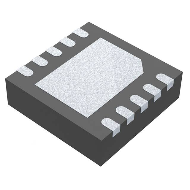


 工商网监
湘ICP备2023018690号
工商网监
湘ICP备2023018690号
