LTC3300-2
Addressable High Efficiency
Bidirectional Multicell
Battery Balancer
DESCRIPTION
FEATURES
Bidirectional Synchronous Flyback Balancing
of Up to 6 Li-Ion or LiFePO4 Cells in Series
n Up to 10A Balancing Current (Set by Externals)
n Integrates Seamlessly with the LTC680x Family of
Multicell Battery Stack Monitors
n Bidirectional Architecture Minimizes Balancing
Time and Power Dissipation
n Up to 92% Charge Transfer Efficiency
n Stackable Architecture Enables >800V Systems
n Uses Simple 2-Winding Transformers
n 1MHz Serial Interface with 4-Bit
CRC Packet Error Checking
n Individually Addressable with 5-Bit Address
n Numerous Fault Protection Features
n 48-Lead Exposed Pad QFN and LQFP Packages
n AEC-Q100 Qualified for Automotive Application
The LTC®3300-2 is a fault-protected controller IC for
transformer-based bidirectional active balancing of multicell battery stacks. All associated gate drive circuitry,
precision current sensing, fault detection circuitry and a
robust serial interface with built-in watchdog timer are
integrated.
n
Each LTC3300-2 can balance up to 6 series-connected
battery cells with an input common mode voltage up to
36V. Charge from any selected cell can be transferred at
high efficiency to or from 12 or more adjacent cells. Each
LTC3300-2 has an individually addressable serial interface,
allowing up to 32 LTC3300-2 devices to interface to one
control processor.
Fault protection features include readback capability, cyclic redundancy check (CRC) error detection, maximum
on-time volt-second clamps, and overvoltage shutoffs.
APPLICATIONS
The related LTC3300-1 offers a serial interface that allows
the serial ports of multiple LTC3300-1 devices to be daisychained without opto-couplers or isolators.
Electric Vehicles/Plug-in HEVs
n High Power UPS/Grid Energy Storage Systems
n General Purpose Multicell Battery Stacks
n
All registered trademarks and trademarks are the property of their respective owners.
TYPICAL APPLICATION
High Efficiency Bidirectional Balancing
NEXT CELL ABOVE
+
CHARGE
RETURN
(IDISCHARGE 1-6)
+
•
CHARGE
RETURN
IDISCHARGE
+
Balancer Efficiency
CELL 12
LTC3300-2
ADDRESS n + 1
4
5
100
ISOLATOR
CELL 7
CELL 6
4
•
4
SERIAL I/O
LTC3300-2
•
CHARGE
SUPPLY
ICHARGE
+
CHARGE TRANSFER EFFICIENCY (%)
CHARGE
SUPPLY
(ICHARGE 1-6)
95
CHARGE
CELL 1
DISCHARGE
90
85
80
4
DC2064A DEMO BOARD
ICHARGE = IDISCHARGE = 2.5A
VCELL = 3.6V
6
8
10
12
NUMBER OF CELLS (SECONDARY SIDE)
33001 TA01b
•
4
ADDRESS n
ISOLATOR
5
33002 TA01a
NEXT CELL BELOW
Document Feedback
Rev. B
For more information www.analog.com
1
�LTC3300-2
ABSOLUTE MAXIMUM RATINGS
(Note 1)
Total Supply Voltage (C6 to V–)..................................36V
Input Voltage (Relative to V–)
C1 ............................................................ –0.3V to 6V
I1P ........................................................ –0.3V to 0.3V
I1S, I2S, I3S, I4S, I5S, I6S..................... –0.3V to 0.3V
CSBI, SCKI, SDI........................................ –0.3V to 6V
VREG, SDO................................................ –0.3V to 6V
RTONP, RTONS............–0.3V to Min[VREG + 0.3V, 6V]
CTRL, BOOST, WDT..... –0.3V to Min[VREG + 0.3V, 6V]
A4, A3, A2, A1, A0........ –0.3V to Min[VREG + 0.3V, 6V]
Voltage Between Pins
Cn to Cn-1*............................................... –0.3V to 6V
InP to Cn-1*........................................... –0.3V to 0.3V
BOOST+ to C6........................................... –0.3V to 6V
SDO Current............................................................10mA
G1P, GnP, G1S, GnS, BOOST– Current................ ±200mA
Operating Junction Temperature Range (Notes 2, 7)
LTC3300I-2......................................... –40°C to 125°C
LTC3300H-2....................................... –40°C to 150°C
Storage Temperature Range................... –65°C to 150°C
*n = 2 to 6
PIN CONFIGURATION
TOP VIEW
49
V–
36 C5
35 G5P
34 I5P
33 C4
32 G4P
31 I4P
30 C3
29 G3P
28 I3P
27 C2
26 G2P
25 I2P
G6S 1
I6S 2
G5S 3
I5S 4
G4S 5
I4S 6
G3S 7
I3S 8
G2S 9
I2S 10
G1S 11
I1S 12
49
V–
36
35
34
33
32
31
30
29
28
27
26
25
C5
G5P
I5P
C4
G4P
I4P
C3
G3P
I3P
C2
G2P
I2P
RTONS 13
RTONP 14
CTRL 15
CSBI 16
SCKI 17
SDI 18
SDO 19
WDT 20
V– 21
I1P 22
G1P 23
C1 24
RTONS 13
RTONP 14
CTRL 15
CSBI 16
SCKI 17
SDI 18
SDO 19
WDT 20
V– 21
I1P 22
G1P 23
C1 24
G6S 1
I6S 2
G5S 3
I5S 4
G4S 5
I4S 6
G3S 7
I3S 8
G2S 9
I2S 10
G1S 11
I1S 12
48
47
46
45
44
43
42
41
40
39
38
37
48 VREG
47 A4
46 A3
45 A2
44 A1
43 A0
42 BOOST
41 BOOST–
40 BOOST+
39 C6
38 G6P
37 I6P
VREG
A4
A3
A2
A1
A0
BOOST
BOOST–
BOOST+
C6
G6P
I6P
TOP VIEW
UK PACKAGE
48-LEAD (7mm × 7mm) PLASTIC QFN
TJMAX = 150°C, θJA = 34°C/W, θJC = 3°C/W
EXPOSED PAD (PIN 49) IS V–, MUST BE SOLDERED TO PCB
LXE PACKAGE
48-LEAD (7mm × 7mm) PLASTIC LQFP
TJMAX = 150°C, θJA = 20.46°C/W, θJC = 3.68°C/W
EXPOSED PAD (PIN 49) IS V–, MUST BE SOLDERED TO PCB
Rev. B
2
For more information www.analog.com
�LTC3300-2
ORDER INFORMATION
LEAD FREE FINISH
LTC3300IUK-2#PBF
TAPE AND REEL
LTC3300IUK-2#TRPBF
PART MARKING
LTC3300UK-2
LTC3300HUK-2#PBF
LTC3300HUK-2#TRPBF
LTC3300UK-2
LEAD FREE FINISH
LTC3300ILXE-2#PBF
TRAY
LTC3300ILXE-2#PBF
PART MARKING
LTC3300LXE-2
LTC3300HLXE-2#PBF
LTC3300HLXE-2#PBF
LTC3300LXE-2
AUTOMOTIVE PRODUCTS*
LEAD FREE FINISH
TRAY
PART MARKING
LTC3300ILXE-2#WPBF
LTC3300ILXE-2#WPBF
LTC3300LXE-2
LTC3300HLXE-2#WPBF
LTC3300HLXE-2#WPBF LTC3300LXE-2
Contact the factory for parts specified with wider operating temperature ranges.
PACKAGE DESCRIPTION
48-Lead (7mm × 7mm) Plastic QFN
48-Lead (7mm × 7mm) Plastic QFN
PACKAGE DESCRIPTION
TEMPERATURE RANGE
–40°C to 125°C
–40°C to 150°C
48-Lead (7mm × 7mm) Plastic eLQFP
TEMPERATURE RANGE
–40°C to 125°C
48-Lead (7mm × 7mm) Plastic eLQFP
–40°C to 150°C
PACKAGE DESCRIPTION
48-Lead (7mm × 7mm) Plastic eLQFP
48-Lead (7mm × 7mm) Plastic eLQFP
TEMPERATURE RANGE
–40°C to 125°C
–40°C to 150°C
Tape and reel specifications. Some packages are available in 500 unit reels through designated sales channels with #TRMPBF suffix.
*Versions of this part are available with controlled manufacturing to support the quality and reliability requirements of automotive applications. These
models are designated with a #W suffix. Only the automotive grade products shown are available for use in automotive applications. Contact your local
Analog Devices account representative for specific product ordering information and to obtain the specific Automotive Reliability reports for these models.
Rev. B
For more information www.analog.com
3
�LTC3300-2
ELECTRICAL
CHARACTERISTICS
The l denotes the specifications which apply over the specified operating
junction temperature range, otherwise specifications are at TA = 25°C. (Note 2) BOOST+ = 25.2V, C6 = 21.6V, C5 = 18V, C4 = 14.4V,
C3 = 10.8V, C2 = 7.2V, C1 = 3.6V, V– = 0V, unless otherwise noted.
SYMBOL
PARAMETER
DC Specifications
Supply Current When Not
IQ_SD
Balancing (Post Suspend or Pre
First Execute)
Supply Current When Balancing
IQ_ACTIVE
(Note 3)
VCELL|MIN
Minimum Cell Voltage (Rising)
Required for Primary Gate Drive
VCELL|MIN(HYST) VCELL|MIN Comparator Hysteresis
Maximum Cell Voltage (Rising)
VCELL|MAX
Before Disabling Balancing
VCELL|MAX(HYST) VCELL|MAX Comparator Hysteresis
VCELL|RECONNECT Maximum Cell Voltage (Falling) to
Re-Enable Balancing
Regulator Pin Voltage
VREG
VREG Voltage (Rising) for
VREG|POR
Power-On Reset
Minimum VREG Voltage (Falling)
VREG|MIN
for Secondary Gate Drive
CONDITIONS
Measured at C1, C2, C3, C4, C5
Measured at C6
Measured at BOOST+
Balancing C1 Only (Note 4 for V–, C2, C6)
Measured at C1
Measured at C2, C3, C4, C5
Measured at C6
Measured at BOOST+
Balancing C2 Only (Note 4 for C1, C3, C6)
Measured at C1
Measured at C2
Measured at C3, C4, C5
Measured at C6
Measured at BOOST+
Balancing C3 Only (Note 4 for C2, C4, C6)
Measured at C1, C4, C5
Measured at C2
Measured at C3
Measured at C6
Measured at BOOST+
Balancing C4 Only (Note 4 for C3, C5, C6)
Measured at C1, C2, C5
Measured at C3
Measured at C4
Measured at C6
Measured at BOOST+
Balancing C5 Only (Note 4 for C4, C6)
Measured at C1, C2, C3
Measured at C4
Measured at C5
Measured at C6
Measured at BOOST+
Balancing C6 Only (Note 4 for C5, C6, BOOST+)
Measured at C1, C2, C3, C4
Measured at C5
Measured at C6
Measured at BOOST+ (BOOST = V–)
Measured at BOOST+ (BOOST = VREG)
Cn to Cn – 1 Voltage to Balance Cn, n = 2 to 6
C1 Voltage to Balance C1
Cn + 1 to Cn Voltage to Balance Cn, n = 1 to 5
BOOST+ to C6 Voltage to Balance C6, BOOST = V–
MIN
TYP
MAX
6
0
14
0
1
22
10
µA
µA
µA
250
70
560
0
375
105
840
10
µA
µA
µA
µA
–70
250
70
560
0
375
105
840
10
µA
µA
µA
µA
µA
–105
–105
–105
–105
–105
l
l
l
l
1.8
1.8
1.8
1.8
l
4.7
l
4.25
9V ≤ C6 ≤ 36V, 0mA ≤ ILOAD ≤ 20mA
l
4.4
VREG Voltage to Balance Cn, n = 1 to 6
l
3.8
C1, Cn to Cn – 1 Voltage to Balance Any Cell,
n = 2 to 6
70
–70
250
560
0
105
70
–70
250
560
0
105
70
–70
250
560
0
105
70
–70
740
60
0
2
2
2
2
70
5
105
375
840
10
375
840
10
375
840
10
1110
90
10
2.2
2.2
2.2
2.2
5.3
0.5
4.8
4.0
UNITS
µA
µA
µA
µA
µA
µA
µA
µA
µA
µA
µA
µA
µA
µA
µA
µA
µA
µA
µA
µA
V
V
V
V
mV
V
V
V
5.2
V
V
V
Rev. B
4
For more information www.analog.com
�LTC3300-2
ELECTRICAL
CHARACTERISTICS
The l denotes the specifications which apply over the specified operating
junction temperature range, otherwise specifications are at TA = 25°C. (Note 2) BOOST+ = 25.2V, C6 = 21.6V, C5 = 18V, C4 = 14.4V,
C3 = 10.8V, C2 = 7.2V, C1 = 3.6V, V– = 0V, unless otherwise noted.
SYMBOL
IREG_SC
PARAMETER
Regulator Pin Short Circuit Current
Limit
RTONP Servo Voltage
VRTONP
RTONS Servo Voltage
VRTONS
WDT Pin Current, Balancing
IWDT_RISING
WDT Pin Current as a Percentage
IWDT_FALLING
of IWDT_RISING, Secondary OV
Primary Winding Peak Current
VPEAK_P
Sense Voltage
VPEAK_P Matching (All 6)
Secondary Winding Peak Current
VPEAK_S
Sense Voltage
VPEAK_S Matching (All 6)
Primary Winding Zero Current
VZERO_P
Sense Voltage (Note 5)
VZERO_P Matching (All 6)
Normalized to Mid-Range VPEAK_P
Secondary Winding Zero Current
VZERO_S
Sense Voltage (Note 5)
VZERO_S Matching (All 6)
Normalized to Mid-Range VPEAK_S
BOOST– Pin Pull-Down RON
RBOOST_L
BOOST– Pin Pull-Up RON
RBOOST_H
Thermal Shutdown Threshold
TSD
(Note 7)
Thermal Shutdown Hysteresis
THYS
Timing Specifications
Primary Winding Gate Drive Rise
tr_P
Time (10% to 90%)
Primary Winding Gate Drive Fall
tf_P
Time (90% to 10%)
Secondary Winding Gate Drive
tr_S
Rise Time (10% to 90%)
Secondary Winding Gate Drive Fall
tf_S
Time (90% to 10%)
Primary Winding Switch Maximum
tONP|MAX
On-Time
tONP|MAX Matching (All 6)
Secondary Winding Switch
tONS|MAX
Maximum On-Time
tONS|MAX Matching (All 6)
Delayed Start Time After New/
tDLY_START
Different Balance Command or
Recovery from Voltage/Temp Fault
SPI Port Timing Specifications
SDI Valid to SCKI Rising Setup
t1
SDI Valid from SCKI Rising Hold
t2
SCKI Low
t3
SCKI High
t4
CONDITIONS
VREG = 0V
MIN
TYP
55
MAX
UNITS
mA
1.2
1.2
80
87.5
1.242
1.242
88
90
V
V
µA
%
50
50
±1.7
50
50
±0.5
–2
–2
±1.7
55
55
±5
55
55
±3
3
3
±5
mV
mV
%
mV
mV
%
mV
mV
%
–7
–7
±0.5
–2
–2
±3
mV
mV
%
RRTONP = 20kΩ
RRTONS = 15kΩ
RTONS = 15kΩ, WDT = 0.5V
RTONS = 15kΩ, WDT = 2V
l
l
1.158
1.158
72
85
I1P
InP to Cn – 1, n = 2 to 6
±[(Max – Min)/(Max + Min)] • 100%
I1S
InS to Cn – 1, n = 2 to 6, CTRL = 0 Only
±[(Max – Min)/(Max + Min)] • 100%
I1P
InP to Cn – 1, n = 2 to 6
±{[(Max – Min)/2]/(VPEAK_P|MIDRANGE)} • 100%
(Note 6)
I1S
InS to Cn – 1, n = 2 to 6, CTRL = 0 Only
±{[(Max – Min)/2]/(VPEAK_S|MIDRANGE)} • 100%
(Note 6)
Measured at 100mA Into Pin, BOOST = VREG
Measured at 100mA Out of Pin, BOOST = VREG
Rising Temperature
l
l
45
45
l
l
l
l
l
45
45
l
l
l
–7
–7
l
l
l
–12
–12
l
2.5
4
155
Ω
Ω
°C
10
°C
G1P Through G6P, CGATE = 2500pF
35
70
ns
G1P Through G6P, CGATE = 2500pF
20
40
ns
G1S, CGATE = 2500pF
G2S Through G6S, CTRL = 0 Only, CGATE = 2500pF
G1S, CGATE = 2500pF
G2S Through G6S, CTRL = 0 Only, CGATE = 2500pF
l
RRTONP = 20kΩ (Measured at G1P-G6P)
6
30
30
20
20
7.2
60
60
40
40
8.4
ns
ns
ns
ns
µs
±[(Max – Min)/(Max + Min)] • 100%
RRTONS = 15kΩ (Measured at G1S-G6S)
l
1
±1
1.2
±4
1.4
%
µs
±[(Max – Min)/(Max + Min)] • 100%
l
±1
2
±4
%
ms
Write Operation
Write Operation
l
l
l
l
l
For more information www.analog.com
10
250
400
400
ns
ns
ns
ns
Rev. B
5
�LTC3300-2
ELECTRICAL
CHARACTERISTICS
The l denotes the specifications which apply over the specified operating
junction temperature range, otherwise specifications are at TA = 25°C. (Note 2) BOOST+ = 25.2V, C6 = 21.6V, C5 = 18V, C4 = 14.4V,
C3 = 10.8V, C2 = 7.2V, C1 = 3.6V, V– = 0V, unless otherwise noted.
SYMBOL
t5
t6
t7
t8
fCLK
tWD1
PARAMETER
CSBI Pulse Width
SCKI Rising to CSBI Rising
CSBI Falling to SCKI Rising
SCKI Falling to SDO Valid
Clock Frequency
Watchdog Timer Timeout Period
tWD2
Watchdog Timer Reset Time
Digital I/O Specifications
Digital Input Voltage High
VIH
VIL
Digital Input Voltage Low
IIH
Digital Input Current High
IIL
Digital Input Current Low
VOL
IOH
Digital Output Voltage Low
Digital Output Current High
CONDITIONS
l
l
l
Read Operation
MIN
400
100
100
TYP
MAX
1.5
250
1
2.25
1.5
5
µs
0.5
0.5
0.5
0.8
1
1
1
1
1
1
1
1
0.3
100
V
V
V
V
V
V
V
V
µA
µA
µA
µA
µA
µA
µA
µA
V
nA
l
l
WDT Assertion Measured from Last Valid
Command Byte
WDT Negation Measured from Last Valid
Command Byte
l
Pins CSBI, SCKI, SDI
Pins CTRL, BOOST
Pins A4, A3, A2, A1, A0
Pin WDT
Pins CSBI, SCKI, SDI
Pins CTRL, BOOST
Pins A4, A3, A2, A1, A0
Pin WDT
Pins CSBI, SCKI, SDI
Pins CTRL, BOOST
Pins A4, A3, A2, A1, A0
Pin WDT, Timed Out
Pins CSBI, SCKI, SDI
Pins CTRL, BOOST
Pins A4, A3, A2, A1, A0
Pin WDT, Not Balancing
Pin SDO, Sinking 500µA; Read
Pin SDO at 6V
l
l
l
l
Note 1: Stresses beyond those listed under Absolute Maximum Ratings
may cause permanent damage to the device. Exposure to any Absolute
Maximum Rating condition for extended periods may affect device
reliability and lifetime.
Note 2: The LTC3300-2 is tested under pulsed load conditions such
that TJ ≈ TA. The LTC3300I-2 is guaranteed over the –40°C to 125°C
operating junction temperature range and the LTC3300H-2 is guaranteed
over the –40°C to 150°C operating junction temperature. High junction
temperatures degrade operating lifetimes; operating lifetime is derated
for junction temperatures greater than 125°C. Note that the maximum
ambient temperature consistent with these specifications is determined by
specific operating conditions in conjunction with board layout, the rated
package thermal impedance and other environmental factors. The junction
temperature (TJ, in °C) is calculated from the ambient temperature
(TA, in °C) and power dissipation (PD, in Watts) according to the formula:
TJ = TA + (PD • θJA)
where θJA (in °C/W) is the package thermal impedance.
Note 3: When balancing more than one cell at a time, the individual cell
supply currents can be calculated from the values given in the table as
follows: First add the appropriate table entries cell by cell for the balancers
0.75
l
VREG – 0.5
VREG – 0.5
VREG – 0.5
2
l
l
l
l
–1
–1
–1
–1
–1
–1
–1
–1
l
l
0
0
0
0
0
0
0
0
UNITS
ns
ns
ns
ns
MHz
second
that are on. Second, for each additional balancer that is on, subtract 70µA
from the resultant sums for C1, C2, C3, C4, and C5, and 450µA from the
resultant sum for C6. For example, if all six balancers are on, the resultant
current for C1 is [250 – 70 + 70 + 70 + 70 + 70 – 5(70)]µA = 110µA and
for C6 is [560 + 560 + 560 + 560 + 560 + 740 – 5(450)]µA = 1290µA.
Note 4: Dynamic supply current is higher due to gate charge being
delivered at the switching frequency during active balancing. See Gate
Drivers/Gate Drive Comparators and Voltage Regulator in the Operation
section for more information on estimating these currents.
Note 5: The zero current sense voltages given in the table are DC
thresholds. The actual zero current sense voltage seen in application will
be closer to zero due to the slew rate of the winding current and the finite
delay of the current sense comparator.
Note 6: The mid-range value is the average of the minimum and maximum
readings within the group of six.
Note 7: This IC includes overtemperature protection intended to protect
the device during momentary overload conditions. The maximum junction
temperature may be exceeded when overtemperature protection is active.
Continuous operation above the specified maximum operating junction
temperature may result in device degradation or failure.
Rev. B
6
For more information www.analog.com
�LTC3300-2
TYPICAL PERFORMANCE CHARACTERISTICS
1.06
C6 = 21.6V
IQ(ACTIVE)/IQ(ACTIVE AT 25°C)
2.05
16
1.95
1.00
14
12
0.98
TYP = 740µA
TYP = 560µA
TYP = 250µA
TYP = 70µA
TYP = 60µA
TYP = –70µA
0.96
0
0.94
–50 –25
25 50
75 100 125 150
TEMPERATURE (°C)
0
5.2
1.80
–50 –25
5.0
CELL VOLTAGE RISING
VREG Load Regulation
4.70
TA = 25°C
4.69
VREG Voltage vs Temperature
IVREG = 10mA
4.68
4.9
C6 = 36V
4.7
4.6
CELL VOLTAGE FALLING
4.4
4.8
4.66
C6 = 9V
VREG (V)
4.8
VREG (V)
VCELL(MAX) (V)
25 50 75 100 125 150
TEMPERATURE (°C)
4.67
4.5
4.65
4.7
4.64
C6 = 36V
4.63
C6 = 9V
4.6
4.62
4.3
4.61
4.2
–50 –25
0
4.5
25 50 75 100 125 150
TEMPERATURE (°C)
0
5
60
C6 = 21.6V
59
C6 = 21.6V
1.224
IVREG (mA)
3.975
VRTONP, VRTONS (V)
57
4.000
1.212
56
1.200
55
54
53
VREG FALLING
(MIN SEC. GATE DRIVE)
52
3.925
3.900
–50 –25
VRTONP, VRTONS vs Temperature
1.236
58
4.050
VREG RISING (POR)
25 50 75 100 125 150
TEMPERATURE (°C)
33002 G07
50
–50 –25
VRTONP
1.188
VRTONS
1.176
51
0
25 50 75 100 125 150
TEMPERATURE (°C)
33002 G06
VREG Short-Circuit Current Limit
vs Temperature
4.075
4.025
0
33002 G05
VREG POR Voltage and Minimum
Secondary Gate Drive vs
Temperature
3.950
4.60
–50 –25
10 15 20 25 30 35 40 45 50
IVREG (mA)
LT33002 G04
VREG (V)
0
33002 G03
4.9
4.100
1.90
33002 G02
Maximum Cell Voltage to Allow
Balancing vs Temperature
5.0
CELL VOLTAGE FALLING
1.85
25 50 75 100 125 150
TEMPERATURE (°C)
33002 G01
5.1
CELL VOLTAGE RISING
2.00
1.02
VCELL(MIN) (V)
IQ(SD) (µA)
2.10
3.6V PER CELL
MATCH CURVE WITH TABLE ENTRY
1.04
18
10
–50 –25
Minimum Cell Voltage Required
for Primary Gate Drive vs
Temperature
Supply Current When Balancing
vs Temperature Normalized to 25°C
C6 Supply Current When Not
Balancing vs Temperature
20
TA = 25°C unless otherwise specified.
0
25 50 75 100 125 150
TEMPERATURE (°C)
33002 G08
1.164
–50 –25
0
25 50 75 100 125 150
TEMPERATURE (°C)
33002 G09
Rev. B
For more information www.analog.com
7
�LTC3300-2
TYPICAL PERFORMANCE CHARACTERISTICS
VRTONP, VRTONS
vs External Resistance
1.236
TA = 25°C unless otherwise specified.
WDT Pin Current vs Temperature
85
TA = 25°C
RTONS = 15k
BALANCING
WDT = 0.5V
1.224
80
VRTONP, VRTONS (V)
WDT Pin Current vs RTONS
240
200
1.212
75
SECONDARY OV
WDT = 2V
1.188
VRTONS
IWDT (µA)
IWDT (µA)
160
1.200
70
VRTONP
10
RTONP, RTONS RESISTANCE (kΩ)
65
–50 –25
100
0
VZERO_P, VZERO_S (mV)
VPEAK_P, VPEAK_S (mV)
49
8.0
0
SECONDARY
–7.5
0
25 50
75 100 125 150
TEMPERATURE (°C)
–10.0
–50 –25
0
20
18
tONP(MAX),tONS(MAX) (µs)
1.1
0
25 50 75 100 125 150
TEMPERATURE (°C)
33002 G16
6.8
Maximum On-Time
vs RTONP, RTONS
0
1.65
1.60
14
12
PRIMARY
10
6
4
10
15
25 30 35
RTONP, RTONS (kΩ)
20
1.45
1.40
SECONDARY
5
1.55
1.50
8
0
25 50 75 100 125 150
TEMPERATURE (°C)
Watchdog Timer Timeout Period
vs Temperature
TA = 25°C
2
1.0
–50 –25
7.2
33002 G15
16
1.2
7.6
33002 G14
Secondary Winding Switch
Maximum On-Time vs Temperature
1.3
45
40
RTONP = 20k
VCELL = 3.6V
6.0
–50 –25
25 50 75 100 125 150
TEMPERATURE (°C)
33002 G13
RTONS = 15k
35
6.4
tWD1 (SECONDS)
45
–50 –25
20 25 30
RTONS (kΩ)
15
PRIMARY
–5.0
47
tONS(MAX) (µs)
8.4
–2.5
SECONDARY
10
Primary Winding Switch Maximum
On-Time vs Temperature
VCELL = 3.6V
RANDOM CELL SELECTED
2.5
51
5
33002 G12
Zero Current Sense Threshold
vs Temperature
5.0
PRIMARY
SECONDARY OV
WDT = 2V
33002 G11
VCELL = 3.6V
RANDOM CELL SELECTED
53
0
25 50 75 100 125 150
TEMPERATURE (°C)
tONP(MAX) (µs)
1
Peak Current Sense Threshold
vs Temperature
1.4
BALANCING
WDT = 0.5V
40
33002 G10
55
120
80
1.176
1.164
TA = 25°C
40
45
33002 G17
1.35
–50 –25
0
25 50 75 100 125 150
TEMPERATURE (°C)
33002 G18
Rev. B
8
For more information www.analog.com
�LTC3300-2
TYPICAL PERFORMANCE CHARACTERISTICS
Balancer Efficiency
vs Cell Voltage
Balance Current vs Cell Voltage
2.7
DC2064A DEMO BOARD
ICHARGE = IDISCHARGE = 2.5A
FOR 12-CELL STACK ONLY
91
90
89
DISCHARGE, 12-CELL STACK
DISCHARGE, 6-CELL STACK
CHARGE, 6-CELL STACK
CHARGE, 12-CELL STACK
2.8
3.0
CHARGE, 12-CELL STACK
2.6
92
3.2 3.4 3.6 3.8
VOLTAGE PER CELL (V)
4.0
4.2
BALANCE CURRENT (A)
CHARGE TRANSFER EFFICIENCY (%)
93
TA = 25°C unless otherwise specified.
DISCHARGE, 12-CELL STACK
2.5
2.4
DISCHARGE, 6-CELL STACK
DC2064A DEMO BOARD
ICHARGE = IDISCHARGE = 2.5A
FOR 12-CELL STACK ONLY
2.3
2.2
2.1
2.8
CHARGE, 6-CELL STACK
3.0
3.8
3.2 3.4 3.6
VOLTAGE PER CELL (V)
4.0
33002 G19
33002 G20
Typical Charge Waveforms
Typical Discharge Waveforms
I1S
50mV/DIV
I1P
50mV/DIV
I1P
50mV/DIV
PRIMARY
DRAIN
50V/DIV
SECONDARY
DRAIN
50V/DIV
I1S
50mV/DIV
2µs/DIV
DC2064A DEMO BOARD
ICHARGE = 2.5A
T=2
S = 12
4.2
33002 G21
SECONDARY
DRAIN
50V/DIV
PRIMARY
DRAIN
50V/DIV
2µs/DIV
DC2064A DEMO BOARD
IDISCHARGE = 2.5A
T=2
S = 12
33002 G22
Rev. B
For more information www.analog.com
9
�LTC3300-2
TYPICAL PERFORMANCE CHARACTERISTICS
TA = 25°C unless otherwise specified.
Protection for Broken Connection
to Secondary Stack While
Discharging
Protection for Broken Connection
to Cell While Charging
~5.2V
C1 PIN
1V/DIV 3.6V
G1P
2V/DIV
CONNECTION TO
C1 BROKEN
BALANCING
SHUTS OFF
50µs/DIV
~66V
SECONDARY
STACK VOLTAGE
10V/DIV 43.2V
G1P
2V/DIV
33002 G23
CONNECTION TO
STACK BROKEN
SCKI
5V/DIV
I1P
50mV/DIV
2ms
CHARGING
DISCHARGING
G1P
2V/DIV
BALANCING
SHUTS OFF
500µs/DIV
Changing Balancer Direction
“On the Fly”
33002 G24
20µs/DIV
33002 G25
Rev. B
10
For more information www.analog.com
�LTC3300-2
PIN FUNCTIONS
Note: The convention adopted in this data sheet is to refer
to the transformer winding paralleling an individual battery
cell as the primary and the transformer winding paralleling
multiple series-stacked cells as the secondary, regardless
of the direction of energy transfer.
G6S, G5S, G4S, G3S, G2S, G1S (Pins 1, 3, 5, 7, 9,
11): G1S through G6S are gate driver outputs for driving
external NMOS transistors connected in series with the
secondary windings of transformers whose primaries are
connected in parallel with battery cells 1 through 6. For
the minimum part count balancing application employing
a single transformer (CTRL = VREG), G2S through G6S
are no connects.
I6S, I5S, I4S, I3S, I2S, I1S (Pins 2, 4, 6, 8, 10, 12): I1S
through I6S are current sense inputs for measuring secondary winding current in transformers whose primaries
are connected in parallel with battery cells 1 through 6.
For the minimum part count balancing application employing a single transformer (CTRL = VREG), I2S through I6S
should be tied to V–.
RTONS (Pin 13): Secondary Winding Max tON Setting
Resistor. The RTONS pin servos to 1.2V. A resistor to
V– programs the maximum on-time for all external NMOS
transistors connected in series with secondary windings.
This protects against a short-circuited current sense resistor in any secondary winding. To defeat this function,
connect RTONS to VREG. The secondary winding OVP
threshold (see WDT pin) is also slaved to the value of the
RTONS resistor.
RTONP (Pin 14): Primary Winding Max tON Setting
Resistor. The RTONP pin servos to 1.2V. A resistor to
V–programs the maximum on-time for all external NMOS
transistors connected in series with primary windings. This
protects against a short-circuited current sense resistor
in any primary winding. To defeat this function, connect
RTONP to VREG.
CTRL: (Pin 15): Control Input. The CTRL pin configures
the LTC3300-2 for the minimum part count application
employing a single transformer if CTRL is tied to VREG or
for the multiple transformer application if CTRL is tied to
V–. This pin must be tied to either VREG or V–.
CSBI (Pin 16): Chip Select (Active Low) Input. The CSBI
pin interfaces to a rail-to-rail output logic gate. See Serial
Port in the Operation section.
SCKI (Pin 17): Serial Clock Input. The SCKI pin interfaces
to a rail-to-rail output logic gate. See Serial Port in the
Operation section.
SDI (Pin 18): Serial Data Input. When writing data to the
LTC3300-2, the SDI pin interfaces to a rail-to-rail output
logic gate. See Serial Port in the Operation section.
SDO (Pin 19): Serial Data Output. When reading data
from the LTC3300-2, the SDO pin is an NMOS open-drain
output. See Serial Port in the Operation section.
WDT (Pin 20): Watchdog Timer Output (Active High). At
initial power-up and when not attempting to execute a valid
balance command, the WDT pin is high impedance and will
be pulled high (internally clamped to ~5.6V) if an external
pull-up resistor is present. While balancing (or attempting to balance but not able to due to voltage/temperature
faults) and during normal communication activity, the WDT
pin is pulled low by a precision current source slaved to
the RTONS resistor. However, if no valid command byte is
written for 1.5 seconds (typical), the WDT output will go
back high. When WDT is high, all balancers are off. The
watchdog timer function can be disabled by connecting
WDT to V–. The secondary winding OVP function can also
be implemented using this pin (See Operation section).
V– (Pin 21, Exposed Pad Pin 49): Connect V– to the most
negative potential in the series of cells. The exposed pad
should be connected to a continuous (ground) plane biased
at V– on the second layer of the printed circuit board by
several vias directly under the LTC3300-2.
I1P, I2P, I3P, I4P, I5P, I6P (Pins 22, 25, 28, 31, 34, 37):
I1P through I6P are current sense inputs for measuring
primary winding current in transformers connected in
parallel with battery cells 1 through 6.
G1P, G2P, G3P, G4P, G5P, G6P (Pins 23, 26, 29, 32, 35,
38): G1P through G6P are gate driver outputs for driving
external NMOS transistors connected in series with the
primary windings of transformers connected in parallel
with battery cells 1 through 6.
Rev. B
For more information www.analog.com
11
�LTC3300-2
PIN FUNCTIONS
C1, C2, C3, C4, C5, C6 (Pins 24, 27, 30, 33, 36, 39):
C1 through C6 connect to the positive terminals of battery cells 1 through 6. Connect the negative terminal of
battery cell 1 to V–.
BOOST+ (Pin 40): Boost+ Pin. Connects to the anode of
the external flying capacitor used for generating sufficient
gate drive necessary for balancing the topmost battery cell
in a given LTC3300-2 sub-stack. A Schottky diode from
C6 to BOOST+ is needed as well. Alternately, the BOOST+
pin can connect to one cell up in the above sub-stack (if
present). This pin is effectively C7. (Note: “Sub-stack” refers
to the 3-6 battery cells connected locally to an individual
LTC3300-2 as part of a larger stack.)
BOOST– (Pin 41): Boost– Pin. Connects to the cathode of
the external flying capacitor used for generating sufficient
gate drive necessary for balancing the topmost battery
cell in a given LTC3300-2 sub-stack. Alternately, if the
BOOST+ pin connects to the next higher cell in the above
sub-stack (if present), this pin is a no connect.
BOOST (Pin 42): Enable Boost Pin. Connect BOOST to VREG
to enable the boosted gate drive needed for balancing the
top cell in a given LTC3300-2 sub-stack. If the BOOST+ pin
can be connected to the next cell up in the stack (i.e., C1
of the next LTC3300-2 in the stack), then BOOST should
be tied to V– and BOOST– no connected. This pin must
be tied to either VREG or V–.
A0, A1, A2, A3, A4 (Pins 43, 44, 45, 46, 47): Address
Inputs. The state of the address pins (VREG = 1, V – = 0)
determines the LTC3300-2 address. These pins must be
tied to either VREG or V –. See Serial Port in the Operation
section.
VREG (Pin 48): Linear Voltage Regulator Output. This 4.8V
output should be bypassed with a 1µF or larger capacitor
to V–. The VREG pin is capable of supplying up to 40mA
to internal and external loads. The VREG pin does not sink
current.
Rev. B
12
For more information www.analog.com
�LTC3300-2
BLOCK DIAGRAM
48
41
VREG
C6
VOLTAGE
REGULATOR
V–
40mA
MAX
4.8V
C6
THERMAL
SHUTDOWN
VREG
40
BOOST –
BOOST +
BOOST
GATE DRIVE
GENERATOR
SD
BOOST
C6
POR
BOOST+
G6P
5
45 A2
ADDRESS
BALANCER
CONTROLLER
46 A3
+
–
+
–
2
C5
44 A1
43 A0
C5
+
47 A4
I6P
0/50mV
I6S
CRC/RCRC
PACKET ERROR
CHECKING
G6S
2
STATUS
12
SDO
PINS 3 TO 10,
25 TO 36
C2
SDI
BALANCER
CONTROLLER
WATCHDOG
TIMER
2
V–
+
–
+
–
SCKI
ACTIVE
1
6-CELL
SYNCHRONOUS
FLYBACK
CONTROLLER
BALANCER
G1P
16
37
V–
DATA
12
C1
17
38
VREG
16
18
39
50mV/0
LEVEL-SHIFTING
SERIAL
INTERFACE
19
42
CSBI
I1P
24
23
22
50mV/0
0/50mV
I1S
12
VREG
20
WDT
RESET
G1S
5.6V
V–
V–
V–
11
MAX ON-TIME
VOLT-SEC
CLAMPS
1.2V
RTONS
V–
21
EXPOSED
PAD
CTRL
49
15
V–
RTONS
13
RTONP
14
33002 BD
Rev. B
For more information www.analog.com
13
�LTC3300-2
TIMING DIAGRAM
Timing Diagram of the Serial Interface
t4
t1
t2
t3
t6
t7
SCKI
SDI
t5
CSBI
t8
SDO
33002 TD
Rev. B
14
For more information www.analog.com
�LTC3300-2
OPERATION
Battery Management System (BMS)
The LTC3300-2 multicell battery cell balancer is a key
component in a high performance battery management
system (BMS) for series-connected Li-Ion cells. It is designed to operate in conjunction with a monitor, a charger,
and a microprocessor or microcontroller (see Figure 1).
The function of the balancer is to efficiently transfer charge
to/from a given out-of-balance cell in the stack from/to
a larger group of neighboring cells (which includes that
individual cell) in order to bring that cell into voltage or
capacity balance with its neighboring cells. Ideally, this
charge would always be transferred directly from/to the
entire stack, but this is impractical for voltage reasons
when the number of cells in the overall stack is large. The
LTC3300-2 is designed to interface to a group of up to 6
series cells, so the number of LTC3300-2 ICs required to
balance a series stack of N cells is N/6 rounded up to the
nearest integer. Since the LTC3300-2 address is 5 bits,
the maximum N can be is 192 cells. For connecting an
individual LTC3300-2 in the stack to fewer than 6 cells,
refer to the Applications Information section.
Because the balancing function entails switching large
(multiampere) currents between cells, precision voltage
monitoring in the BMS is better served by a dedicated
monitor component such as the LTC6803-2 or one of its
family of parts. The LTC6803-2 provides for high precision
A/D monitoring of up to 12 series cells. The only voltage
monitoring provided by the LTC3300-2 is a coarse “outof-range” overvoltage and undervoltage cell balancing
disqualification, which provides a safety shutoff in the
event Kelvin sensing to the monitor component is lost.
In the process of bringing the cells into balance, the overall stack is slightly discharged. The charger component
provides a means for net charging of the entire stack from
an alternate power source.
The last component in the BMS is a microprocessor/
microcontroller which communicates directly with the
balancer, monitor, and charger to receive voltage, current, and temperature information and to implement a
balancing algorithm.
There is no single balancing algorithm optimal for all
situations. For example, during net charging of the overall
stack, it may be desirable to discharge the highest voltage
cells first to avoid reaching terminal charge on any cell
before the entire stack is fully charged. Similarly, during
net discharging of the overall stack, it may be desirable
to charge the lowest voltage cells first to keep them from
reaching a critically low level. Other algorithms may
prioritize fastest time to overall balance. The LTC3300-2
implements no algorithm for balancing the stack. Instead it
provides maximum flexibility by imposing no limitation on
the algorithm implemented as all individual cell balancers
can operate simultaneously and bidirectionally.
Unidirectional Versus Bidirectional Balancing
Most balancers in use today employ a unidirectional (discharge only) approach. The simplest of these operate by
switching in a resistor across the highest voltage cell(s)
in the stack (passive balancing). No charge is recovered
in this approach -instead it is dissipated as heat in the
resistive element. This can be improved by employing an
energy storage element (inductive or capacitive) to transfer
Rev. B
For more information www.analog.com
15
�LTC3300-2
OPERATION
TOP OF STACK
ICHARGE
+
C6
C5
C4
LTC3300-2
BALANCER C3
DIGITAL
ISOLATOR
C2
V–
C1
CELL N
+
CELL N – 1
+
CELL N – 2
+
CELL N – 3
+
CELL N – 4
+
CELL N – 5
+
C6
C5
C4
LTC3300-2
C3
BALANCER
DIGITAL
ISOLATOR
CN
C2
V–
C1
CELL N – 6
+
CELL N – 7
+
C11
C12
ILOAD
C10
C9
C8
C7
C6 LTC6803-2
MONITOR
C5
C4
CELL N – 8
C3
+
CELL N – 9
+
CELL N – 10
+
C2
–
C1
V
C11
C12
CELL N – 11
DIGITAL
ISOLATOR
•
•
•
CHARGER
+
V–
C6
LTC3300-2
BALANCER
DIGITAL
ISOLATOR
C5
C4
C3
C2
V–
C1
+
+
+
+
+
+
C6
LTC3300-2
BALANCER
V–
C5
C4
C3
+
+
+
C2
+
C1
+
CELL 12
CELL 11
CELL 10
CELL 9
CELL 8
CELL 7
CELL 6
CELL 5
CELL 4
C10
C9
C8
C7
C6
LTC6803-2
MONITOR
C5
C4
C3
CELL 3
CELL 2
CELL 1
C2
C1
V–
VCC
µP/µC
VEE
SERIAL COMMUNICATION BUS
33002 F01
Figure 1. LTC3300-2/LTC6803-2 Typical Battery Management System (BMS)
Rev. B
16
For more information www.analog.com
�LTC3300-2
OPERATION
Synchronous Flyback Balancer
charge from the highest voltage cell(s) in the stack to other
lower voltage cells in the stack (active balancing). This
can be very efficient (in terms of charge recovery) for the
case where only a few cells in the overall stack are high,
but will be very inefficient (and time consuming) for the
case where only a few cells in the overall stack are low. A
bidirectional active balancing approach, such as employed
by the LTC3300-2, is needed to achieve minimum balancing time and maximum charge recovery for all common
cell capacity errors.
The balancing architecture implemented by the LTC3300‑2
is bidirectional synchronous flyback. Each LTC3300-2
contains six independent synchronous flyback controllers
that are capable of directly charging or discharging an
individual cell. Balance current is scalable with external
components. Each balancer operates independently of
the others and provides a means for bidirectional charge
transfer between an individual cell and a larger group of
adjacent cells. Refer to Figure 2.
Single-Cell Discharge Cycle for Cell 1
IPRIMARY
ICHARGE
VTOP_OF_STACK
ISECONDARY
+
+
CELL N
CELL 13
ISECONDARY
t
5µs
ILOAD
IPRIMARY
•
+
LPRI
10µH
VSECONDARY
•
–IPRIMARY
–ISECONDARY
CELL 12
G1P
I1S
RSNS_SEC
25mΩ
5µs
t
~417ns
50mV
52V
48V
t
52V
48V
CELL 2
VSECONDARY
VPRIMARY
CELL 1
4V
50mV
4V
50mV
t
t
VPRIMARY
G1S
2A
(48V)
(4V)
T:1
t
~417ns
2A
52.05V
+
IPEAK_SEC = 2A
(I1S = 50mV)
IPEAK_PRI = 2A
(I1P = 50mV)
VCC
+
Single-Cell Charge Cycle for Cell 1
52V
50mV
48V
48V
52V
51.95V
I1P
RSNS_PRI
25mΩ
VPRIMARY
VSECONDARY
4V
50mV
t
4V
50mV
t
33002 F02
Figure 2. Synchronous Flyback Balancing Example with T = 1, S = 12
Rev. B
For more information www.analog.com
17
�LTC3300-2
OPERATION
Cell Discharging (Synchronous)
When discharging is enabled for a given cell, the primary
side switch is turned on and current ramps in the primary
winding of the transformer until the programmed peak
current (IPEAK_PRI) is detected at the In P pin. The primary
side switch is then turned off, and the stored energy in
the transformer is transferred to the secondary-side cells
causing current to flow in the secondary winding of the
transformer. The secondary-side synchronous switch
is turned on to minimize power loss during the transfer
period until the secondary current drops to zero (detected
at In S). Once the secondary current reaches zero, the
secondary switch turns off and the primary-side switch is
turned back on thus repeating the cycle. In this manner,
charge is transferred from the cell being discharged to
all of the cells connected between the top and bottom of
the secondary side—thereby charging the adjacent cells.
In the example of Figure 2, the secondary-side connects
across 12 cells including the cell being discharged.
IPEAK_PRI is programmed using the following equation:
IPEAK _PRI =
50mV
RSNS_PRI
Cell discharge current (primary side) and secondary-side
charge recovery current are determined to first order by
the following equations:
I
⎛ S ⎞
IDISCHARGE = PEAK _PRI ⎜
⎝ S+ T ⎟⎠
2
ISECONDARY =
IPEAK _PRI ⎛ 1 ⎞
⎜⎝
⎟ η
2
S+ T ⎠ DISCHARGE
at the In S pin), the secondary switch is turned off and
current then flows in the primary side thus charging the
selected cell from the entire stack of secondary cells. As
with the discharging case, the primary-side synchronous
switch is turned on to minimize power loss during the cell
charging phase. Once the primary current drops to zero,
the primary switch is turned off and the secondary-side
switch is turned back on thus repeating the cycle.
IPEAK_SEC is programmed using the following equation:
ICHARGE =
RSNS_ SEC
IPEAK _ SEC ⎛ ST ⎞
⎜⎝
⎟ η
2
S+ T ⎠ CHARGE
ISECONDARY =
IPEAK _ SEC ⎛ T ⎞
⎜⎝
⎟
2
S+ T ⎠
where S is the number of secondary cells in the stack, 1:T
is the transformer turns ratio from primary to secondary,
and ηCHARGE is the transfer efficiency from secondary-side
stack discharge to the primary-side cell.
Each balancer’s charge transfer “frequency” and duty
factor depend on a number of factors including IPEAK_PRI,
IPEAK_SEC, transformer winding inductances, turns ratio,
cell voltage and the number of secondary-side cells.
The frequency of switching seen at the gate driver outputs
is given by:
fDISCHARGE =
When charging is enabled for a given cell, the secondaryside switch for the enabled cell is turned on and current flows
from the secondary-side cells through the transformer.
Once IPEAK_SEC is reached in the secondary side (detected
50mV
Cell charge current and corresponding secondary-side
discharge current are determined to first order by the
following equations:
where S is the number of secondary-side cells, 1:T is the
transformer turns ratio from primary to secondary, and
ηDISCHARGE is the transfer efficiency from primary cell
discharge to the secondary side stack.
Cell Charging
IPEAK _ SEC =
fCHARGE =
VCELL
S
•
S+ T LPRI •IPEAK _PRI
VCELL
S
•
S+ T LPRI •IPEAK _ SEC • T
where LPRI is the primary winding inductance.
Figure 3 shows a fully populated LTC3300-2 application
employing all six balancers.
Rev. B
18
For more information www.analog.com
�LTC3300-2
OPERATION
6.8Ω
0.1µF
BOOST–
BOOST+
UP TO •
CELL 12 ••
C6
10µF
1:1
•
10µH
10µH
•
G6P
+
CELL 6
I6P
25mΩ
G6S
I6S
25mΩ
C5
10µF
1:1
•
10µH
10µH
•
G5P
+
I5P
CELL 5
25mΩ
G5S
I5S
25mΩ
C4
LTC3300-2
•
•
•
•
•
•
C3
C2
10µF
1:1
•
10µH
10µH
•
G2P
A4
A3
A2
A1
A0
SERIAL
COMMUNICATION
RELATED
PINS
+
CELL 2
I2P
25mΩ
G2S
CSBI
SCKI
SDI
SDO
I2S
25mΩ
C1
WDT
10µF
1:1
•
10µH
10µH
•
G1P
+
I1P
CELL 1
25mΩ
VREG
G1S
BOOST
I1S
25mΩ
CTRL
10µF
RTONP
RTONS
22.6k
V–
6.98k
33002 F03
•
•
•
Figure 3. LTC3300-2 6-Cell Active Balancer Module Showing Power Connections for the Multi-Transformer Application (CTRL = V–)
Rev. B
For more information www.analog.com
19
�LTC3300-2
OPERATION
Balancing High Voltage Battery Stacks
TOP
Balancing series connected batteries which contain >>12
cells in series requires interleaving of the transformer secondary connections in order to achieve full stack balancing
while limiting the breakdown voltage requirements of the
primary- and secondary-side power FETs. Figure 4 shows
typical interleaved transformer connections for a multicell
battery stack in the generic sense, and Figure 5 for the
specific case of an 18-cell stack. In these examples, the
secondary side of each transformer is connected to the
top of the cell that is 12 positions higher in the stack than
the bottom of the lowest voltage cell in each LTC3300-2
sub-stack. For the top most LTC3300-2 in the stack, it is
not possible to connect the secondary side of the transformer across 12 cells. Instead, it is connected to the top
of the stack, or effectively across only 6 cells. Interleaving
in this fashion allows charge to transfer between 6-cell
sub-stacks throughout the entire battery stack.
LTC3300-2
PRI POWER STAGES SEC
•
•
•
•
FROM CELL N-12
SECONDARY
•
TO CELL 24
LTC3300-2
SEC POWER STAGES
•
•
•
PRI
•
+
•
CELL 18
•
•
•
•
+
CELL 13
•
LTC3300-2
PRI POWER STAGES SEC
•
+
CELL 12
•
•
•
•
LTC3300-2
SEC POWER STAGES
•
• •
• •
R
tON(MAX)|SECONDARY = 1.2µs TONS
15kΩ
• •
• •
For more information on selecting the appropriate
maximum on-times, refer to the Applications Information
section.
•
PRI
+
• •
•
+
CELL 7
R
tON(MAX)|PRIMARY = 7.2µs TONP
20kΩ
To defeat this function, short the appropriate RTON pin(s)
to VREG.
•
+
CELL N-6
Max On-Time Volt-Sec Clamps
The LTC3300-2 contains programmable fault protection
clamps which limit the amount of time that current is
allowed to ramp in either the primary or secondary windings in the event of a shorted sense resistor. Maximum
on time for all primary connections (active during cell
discharging) and all secondary connections (active during
cell charging) is individually programmable by connecting
resistors from the RTONP and RTONS pins to V– according
to the following equations:
•
+
CELL N
+
+
+
+
+
CELL 6
CELL 5
CELL 4
CELL 3
CELL 2
CELL 1
•
33002 F04
Figure 4. Diagram of Power Transfer Interleaving Through the
Stack, Transformer Connections for High Voltage Stacks
Rev. B
20
For more information www.analog.com
�LTC3300-2
OPERATION
0.1µF
6.8Ω
BOOST– BOOST+ C6
+
TO TRANSFORMER
SECONDARIES OF
BALANCERS 14 TO 18
C1
CELL 18
•1:1
10µF
10µH
10µH
•
LTC3300-2
G1P
+
I1P
CELL 13
25mΩ
G1S
I1S
25mΩ
VREG
BOOST
V–
BOOST+
C6
TO TRANSFORMER
SECONDARIES OF
BALANCERS 8 TO 12
C1
+
CELL 12
•1:1
10µF
10µH
10µH
•
LTC3300-2
G1P
+
I1P
CELL 7
25mΩ
G1S
I1S
25mΩ
BOOST
V–
BOOST+
C6
TO TRANSFORMER
SECONDARIES OF
BALANCERS 2 TO 6
C1
+
CELL 6
•1:1
10µF
10µH
10µH
•
LTC3300-2
G1P
+
I1P
CELL 1
25mΩ
G1S
I1S
25mΩ
BOOST
V–
33002 F05
Figure 5. 18-Cell Active Balancer Showing Power Connections, Interleaved
Transformer Secondaries and BOOST+ Rail Generation Up the Stack
Rev. B
For more information www.analog.com
21
�LTC3300-2
OPERATION
Gate Drivers/Gate Drive Comparators
All secondary-side gate drivers (G1S through G6S) are
powered from the VREG output, pulling up to 4.8V when
on and pulling down to V– when off. All primary-side
gate drivers (G1P through G6P) are powered from their
respective cell voltage and the next cell voltage higher in
the stack (see Table 1). An individual cell balancer will only
be enabled if its corresponding cell voltage is greater than
2V and the cell voltage of the next higher cell in the stack
is also greater than 2V. For the G6P gate driver output,
the next higher cell in the stack is C1 of the next higher
LTC3300-2 in the stack (if present) and is only used if the
boosted gate drive is disabled (by connecting BOOST =
V–). If the boosted gate drive is enabled (by connecting
BOOST = VREG), only the C6 cell voltage is looked at to
enable balancing of Cell 6. In the case of the topmost
LTC3300-2 in the stack, the boosted gate drive must be
enabled. The boosted gate drive requires an external diode
from C6 to BOOST+ and a boost capacitor from BOOST+ to
BOOST–. For information on selecting these components,
refer to the Applications Information section. Also note
that the dynamic supply current referred to in Note 4 of
the Electrical Characteristics table adds to the terminal
currents of the pins indicated in the Voltage When Off and
Voltage When On columns of Table 1.
The gate drive comparators have a DC hysteresis of 70mV.
For improved noise immunity, the inputs are internally
low pass filtered and the outputs are filtered so as to
not transition unless the internal comparator state is
unchanged for 3µs to 6µs (typical). If insufficient gate drive
is detected while active balancing is in progress (perhaps,
for example, if the stack is under heavy load), the affected
balancer(s) and only the affected balancer(s) will shut off.
The balance command remains stored in memory, and
active balancing will resume where it left off if sufficient
gate drive is subsequently restored. This can happen if,
for example, the stack is being charged.
Cell Overvoltage Comparators
In addition to sufficient gate drive being required to enable balancing, there are additional comparators which
disable all active balancing if any of the six individual cell
voltages is greater than 5V. These comparators have a
DC hysteresis of 500mV. For improved noise immunity,
the inputs are internally low pass filtered and the outputs
are filtered so as to not transition unless the internal
comparator state is unchanged for 3µs to 6µs (typical).
If any cell voltage goes overvoltage while active balancing is in progress, all active balancers will shut off. The
balance command remains stored in memory, and active
balancing will resume where if left off if the cell voltage
subsequently comes back in range. These comparators
will protect the LTC3300-2 if a connection to a battery is
lost while balancing and the cell voltage is still increasing
as a result of that balancing.
Voltage Regulator
A linear voltage regulator powered from C6 creates a
4.8V rail at the VREG pin which is used for powering
certain internal circuitry of the LTC3300-2 including all 6
secondary gate drivers. The VREG output can also be used
for powering external loads, provided that the total DC
loading of the regulator does not exceed 40mA at which
point current limit is imposed to limit on-chip power dis-
Table 1.
DRIVER OUTPUT
VOLTAGE WHEN OFF
VOLTAGE WHEN ON
GATE DRIVE REQUIRED TO ENABLE BALANCING
G1P
V-
C2
(C2 – C1) ≥ 2V and (C1 – V–) ≥2V
G2P
C1
C3
(C3 – C2) ≥ 2V and (C2 – C1) ≥2V
G3P
C2
C4
(C4 – C3) ≥ 2V and (C3 – C2) ≥2V
G4P
C3
C5
(C5 – C4) ≥ 2V and (C4 – C3) ≥2V
G5P
C4
C6
(C6 – C5) ≥ 2V and (C5 – C4) ≥2V
G6P
C5
If BOOST = VREG: BOOST+ (Generated)
(C6 – C5) ≥ 2V
If BOOST = V–: BOOST+ = C7*
(C7* – C6) ≥ 2V and (C6 – C5) ≥ 2V
*C7 is equal to C1 of the next higher LTC3300-2 in the stack if this connection is used.
Rev. B
22
For more information www.analog.com
�LTC3300-2
OPERATION
sipation. The internal component of the DC load current
is dominated by the average gate driver current(s) (G1S
through G6S), each approximated by C • V • f, where C
is the gate capacitance of the external NMOS transistor,
V = VREG = 4.8V, and f is the frequency that the gate
driver output is running at. FET manufacturers usually
specify the C • V product as Qg (gate charge) measured
in coulombs at a given gate drive voltage. The frequency,
f, is dependent on many terms, primarily the voltage of
each individual cell, the number of cells in the secondary
stack, the programmed peak balancing current, and the
transformer primary and secondary winding inductances.
In a typical application, the C • V • f current loading the
VREG output is expected to be low single-digit milliamperes
per driver. Note that the VREG loading current is ultimately
delivered from the C6 pin. For applications involving very
large balance currents and/or employing external NMOS
transistors with very large gate capacitance, the VREG
output may need to source more than 40mA average. For
information on how to design for these situations, refer
to the Applications Information section.
One additional function slaved to the VREG output is
the power-on reset (POR). During initial power-up and
subsequently if the VREG pin voltage ever falls below approximately 4V (e.g., due to overloading), the serial port
is cleared to the default power-up state with no balancers
active. This feature thus guarantees that the minimum gate
drive provided to the external secondary side FETs is also
4V. For a 10µF capacitor loading the output at initial powerup, the output reaches regulation in approximately 1ms.
Thermal Shutdown
The LTC3300-2 has an overtemperature protection circuit
which shuts down all active balancing if the internal silicon
die temperature rises to approximately 155°C. When in
thermal shutdown, all serial communication remains active
and the cell balancer status (which contains temperature
information) can be read back. The balance command
which had been being executed remains stored in memory.
This function has 10°C of hysteresis so that when the die
temperature subsequently falls to approximately 145°C,
active balancing will resume with the previously executing command.
Watchdog Timer Circuit
The watchdog timer circuit provides a means of shutting
down all active balancing in the event that communication
to the LTC3300-2 is lost. The watchdog timer initiates
when a balance command begins executing and is reset
to zero every time a valid 8-bit command byte (see Serial
Port Operation) is written. The valid command byte can
be an execute, a write, or a read (command or status).
“Partial” reads and writes are considered valid, i.e., it is
only necessary that the first 8 bits have to be written and
contain the correct address.
Referring to Figure 6a, at initial power-up and when not
balancing, the WDT pin is high impedance and will be
pulled high (internally clamped to ~5.6V) if an external
pull-up resistor is present. While balancing and during
normal communication activity, the WDT pin is pulled
low by a precision current source equal to 1.2V/RTONS.
(Note: if the secondary volt-second clamp is defeated
by connecting RTONS to VREG, the watchdog function is
also defeated.) If no valid command byte is written for
1.5 seconds (typical), the WDT output will go back high.
When WDT is high, all balancers will be shut down but
the previously executing balance command still remains
in memory. From this timed-out state, a subsequent valid
command byte will reset the timer, but the balancers will
only restart if an execute command is written. To defeat
the watchdog function, simply connect the WDT pin to V–.
Pause/Resume Balancing (via WDT Pin)
The WDT output pin doubles as a logic input (TTL levels)
which can be driven by an external logic gate as shown in
Figure 6b (no watchdog), or by a PMOS/three-state logic
gate as shown in Figure 6c (with watchdog) to pause and
resume balancing in progress. The external pull-up must
have sufficient drive capability to override the current source
to ground at the WDT pin (= 1.2V/RTONS). Provided that
the internal watchdog timer has not independently timed
out, externally pulling the WDT pin high will immediately
pause balancing, and it will resume where it left off when
the pin is released.
Rev. B
For more information www.analog.com
23
�LTC3300-2
OPERATION
balance command remains stored in memory, and active
balancing will resume where it left off if the stack voltage
subsequently falls to a safer level.
Secondary Winding OVP Function (via WDT pin)
The precision current source pull-down on the WDT pin
during balancing can be used to construct an accurate
secondary winding OVP protection circuit as shown in
Figure 6c. A second external resistor, scaled to RTONS
and connected to the transformer secondary winding, is
used to set the comparator threshold. An NMOS cascode
device (with gate tied to VREG) is also needed to protect
the WDT pin from high voltage. The secondary winding
OVP thresholds are given by:
Single Transformer Application (CTRL = VREG)
Figure 7 shows a fully populated LTC3300-2 application
employing all six balancers with a single shared custom
transformer. In this application, the transformer has six
primary windings coupled to a single secondary winding.
Only one balancer can be active at a given time as all six
share the secondary gate driver G1S and secondary current
sense input I1S. The unused gate driver outputs G2S-G6S
must be left floating and the unused current sense inputs
I2S-I6S should be connected to V–. Any balance command
which attempts to operate more than one balancer at a time
will be ignored. This application represents the minimum
component count active balancer achievable.
VSEC|OVP(RISING) = 1.4V + 1.2V • (RSEC_OVP/RTONS)
VSEC|OVP(FALLING) = 1.4V + 1.05V • (RSEC_OVP/RTONS)
This comparator will protect the LTC3300-2 application
circuit if the secondary winding connection to the battery
stack is lost while balancing and the secondary winding
voltage is still increasing as a result of that balancing. The
VREG
VREG
VTH = 1.4V
LTC3300-2
WDT
RWDT
WDT
1.2V
RTONS
RTONS
1.2V
RTONS
RTONS
V–
PAUSE/
RESUME
5.6V
ACTIVE
5.6V
ACTIVE
LTC3300-2
RTONS
RTONS
33002 F06b
33002 F06a
(6a) Watchdog Timer Only (WDT = V– to Defeat)
(6b) Pause/Resume Balancing Only
TO TRANSFORMER
SECONDARY WINDINGS
RSEC_OVP
LTC3300-2
WDT
VREG
PAUSE/
RESUME
VREG
EITHER/OR
ACTIVE
5.6V
1.2V
RTONS
VREG
VREG
RTONS
PAUSE/
RESUME
RTONS
33002 F06c
(6c) Watchdog Timer with Pause/Resume Balancing and Secondary Winding OVP Protection
Figure 6. WDT Pin Connection Options
Rev. B
24
For more information www.analog.com
�LTC3300-2
OPERATION
0.1µF
6.8Ω
•
•
•
BOOST– BOOST+
UP TO CELL 12
EACH
1:1 •
C6
10µH
10µF
•
G6P
I6P
+
C5
25mΩ
CELL 6
10µH
10µF
•
G5P
I5P
+
C4
25mΩ
CELL 5
10µH
10µF
•
G4P
I4P
+
LTC3300-2
C3
25mΩ
CELL 4
10µH
10µF
•
G3P
I3P
+
C2
25mΩ
CELL 3
10µH
10µF
G2P
A4
A3
A2
A1
A0
SERIAL
COMMUNICATION
RELATED
PINS
•
I2P
+
C1
CSBI
SCKI
SDI
SDO
25mΩ
CELL 2
10µH
10µF
•
G1P
WDT
I1P
25mΩ
G1S
VREG
I1S
G2S-G6S
I2S-I6S
CTRL
V–
RTONP RTONS
BOOST
10µF
22.6k
NC
+
CELL 1
25mΩ
33002 F07
6.98k
Figure 7. LTC3300-2 6-Cell Active Balancer Module Showing Power Connections for the Single Transformer Application (CTRL = VREG)
Rev. B
For more information www.analog.com
25
�LTC3300-2
OPERATION
SERIAL PORT OPERATION
Data Link Layer
Overview
The LTC3300-2 has an SPI bus compatible serial port.
Devices can be connected in parallel, using digital isolators.
Multiple devices are uniquely identified by a part address
determined by the A0 to A4 pins.
Physical Layer
On the LTC3300-2, four pins comprise the serial interface:
CSBI, SCKI, SDI and SDO. The SDO and SDI pins may
be tied together, if desired, to form a single bidirectional
port. Five address pins (A0 to A4) set the part address.
All serial communication related pins are voltage mode
with voltage levels referenced to the VREG and V – supplies.
Clock Phase and Polarity: The LTC3300-2 SPI-compatible
interface is configured to operate in a system using
CPHA = 1 and CPOL = 1. Consequently, data on SDI must
be stable during the rising edge of SCKI.
Data Transfers: Every byte consists of 8 bits. Bytes are
transferred with the most significant bit (MSB) first. On a
write, the data value on SDI is latched into the device on
the rising edge of SCKI (Figure 8a). Similarly, on a read,
the data value on SDO is valid during the rising edge of
SCKI and transitions on the falling edge of SCKI (Figure 8b).
CSBI must remain low for the entire duration of a command sequence, including between a command byte and
subsequent data. On a write command, data is latched in
on the rising edge of CSBI.
CSBI
SCKI
SDI
MSB (CMD)
LSB (CMD)
MSB (DATA)
LSB (DATA)
(8a) Transmission Format (Write)
CSBI
SCKI
SDI
MSB (CMD)
LSB (CMD)
SDO
MSB (DATA)
(8b) Transmission Format (Read)
LSB (DATA)
33002 F08
Figure 8.
Rev. B
26
For more information www.analog.com
�LTC3300-2
OPERATION
Command Byte
Write Balance Command
All communication to the LTC3300-2 takes place with CSBI
logic low. The first 8 clocked in data bits after a high-tolow transition on CSBI represent the command byte. The
8-bit command byte is written MSB first per Table 2. The
first 5 bits must match the fixed pin-strapped address
[A4 A3 A2 A1 A0] for the individual device, or all subsequent data will be ignored until CSBI transitions high
and then low again. The 6th and 7th bits program one of
four commands as shown in Table 3. The 8th bit in the
command byte must be set such that the entire 8-bit command byte has even parity. If the parity is incorrect, the
current balance command being executed (from the last
previously successful write) is terminated immediately and
all subsequent (write) data is ignored until CSBI transitions high and then low again. Incorrect parity takes this
action whether or not the address matches. This thereby
provides a fast means to immediately terminate balancingin-progress by intentionally writing a command byte with
incorrect parity.
If the command bits program Write Balance Command,
all subsequent write data must be exactly 16 bits (before
CSBI transitions high) or it will be ignored. The internal
command holding register will be cleared which can be
verified on readback. The current balance command being
executed (from the last previously successful write) will
continue, but all active balancing will be turned off if an
Execute Balance Command is subsequently written. Only
the individual LTC3300-2 in the stack with the matching
address will load in the write data. The 16-bit write balance
command is written MSB first per Table 4.
Table 2. Command Byte Bit Mapping
(Defaults to 0x00 in Reset State)
A4
(MSB)
A3
A2
A1
A0
CMDA CMDB
Parity Bit
(LSB)
Table 3. Command Bits
CMDA
0
0
1
1
CMDB
0
1
0
1
The first 12 bits of the 16-bit balance command are used
to indicate which balancer (or balancers) is active and in
which direction (charge or discharge). Each of the 6 cell
balancers is controlled by 2 bits of this data per Table 5.
The balancing algorithm for a given cell is:
Charge Cell n: Ramp up to IPEAK in secondary winding,
ramp down to IZERO in primary winding. Repeat.
Discharge Cell n (Synchronous): Ramp up to Ipeak in
primary winding, ramp down to IZERO in secondary
winding. Repeat.
Table 5. Cell Balancer Control Bits
COMMUNICATION ACTION
Write Balance Command (without Executing)
Readback Balance Command
Read Balance Status
Execute Balance Command
Dn A
Dn B
BALANCING ACTION (n = 1 to 6)
0
0
None
0
1
Discharge Cell n (Nonsynchronous)
1
0
Discharge Cell n (Synchronous)
1
1
Charge Cell n
Table 4. Write Balance Command Data Bit Mapping (Defaults to 0x000F in Reset State)
D1A
(MSB)
D1B
D2A
D2B
D3A
D3B
D4A
D4B
D5A
D5B
D6A
D6B
CRC[3] CRC[2] CRC[1] CRC[0]
(LSB)
Rev. B
For more information www.analog.com
27
�LTC3300-2
OPERATION
For nonsynchronous discharging of cell n, both the secondary winding gate drive and (zero) current sense amp
are disabled. The secondary current will conduct either
through the body diode of the secondary switch (if present) or through a substitute Schottky diode. The primary
will only turn on again after the secondary winding Voltsec clamp times out. In a bidirectional application with a
secondary switch, it may be possible to achieve slightly
higher discharge efficiency by opting for nonsynchronous
discharge mode (if the gate charge savings exceed the
added diode drop losses) but the balancing current will be
less predictable because the secondary winding Volt-sec
clamp must be set longer than the expected time for the
current to hit zero in order to guarantee no current reversal. In the case where a Schottky diode replaces the secondary switch, it is possible to build a undirectional
discharge-only balancing application charging an isolated
auxiliary cell as shown in Figure 16 in the Typical Applications section.
In the CTRL = 1 application of Figure 7 employing a single
transformer which can only balance one cell at a time,
any command requesting simultaneous balancing of more
than one cell will be ignored. All active balancing will be
turned off if an Execute Balance Command is subsequently written.
The last 4 bits of the 16-bit balance command are used
for packet error checking (PEC). The 16 bits of write data
(12-bit message plus 4-bit CRC) are input to a cyclic redundancy check (CRC) block employing the International
Telecommunication Union CRC-4 standard characteristic
polynomial:
x4 + x + 1
In the write data, the 4-bit CRC appended to the message
must be selected such that the remainder of the CRC division is zero. Note that the CRC bits in the Write Balance
Command are inverted. This was done so that an “all zeros”
command is invalid. The LTC3300-2 will ignore the write
data if the remainder is not zero and the internal command
holding register will be cleared which can be verified on
readback. The current balance command being executed
(from the last previously successful write) will continue,
but all active balancing will be turned off if an Execute Balance Command is subsequently written. For information
on how to calculate the CRC including an example, refer
to the Applications Information section.
Readback Balance Command
The bit mapping for Readback Balance Command is identical to that for Write Balance Command. If the command
bits program Readback Balance Command, the 16 bits of
previously written data (latched in 12-bit message plus
newly calculated 4-bit CRC) are shifted out in the same
order bitwise (MSB first) per Table 4. Only the individual LTC3300-2 in the stack with the matching address
will send out the read data. This command allows for
microprocessor verification of written commands before
executing. Note that the CRC bits in the Readback Balance
Command are also inverted. This was done so that an “all
zeros” readback is invalid.
Read Balance Status
If the command bits program Read Balance Status, 16 bits
of status data (12 bits of data plus associated 4-bit CRC)
are shifted out MSB first per Table 6. Similar to a Readback
Balance Command, the last 4 bits in each 16-bit balance
status are used for error detection. The first 12 bits of
the status are input to a cyclic redundancy check (CRC)
block employing the same characteristic polynomial used
for write commands. The LTC3300-2 will calculate and
append the appropriate 4-bit CRC to the outgoing 12‑bit
message which can then be used for microprocessor er-
Table 6. Read Balance Status Data Bit Mapping (defaults to 0x000F in Reset State)
Gate
Gate
Gate
Gate
Gate
Gate
Cells
Sec
Drive 1 Drive 2 Drive 3 Drive 4 Drive 5 Drive 6 Not OV Not OV
OK
OK
OK
OK
OK
OK
(MSB)
Temp
OK
0
0
0
CRC[3] CRC[2] CRC[1] CRC[0]
(LSB)
Rev. B
28
For more information www.analog.com
�LTC3300-2
OPERATION
ror checking. Only the individual LTC3300-2 in the stack
with the matching address will send out the status data.
Note that the CRC bits in the Read Balance Status are
inverted. This was done so that an “all zeros” readback
is invalid.
The first 6 bits of the read balance status indicate if there
is sufficient gate drive for each of the 6 balancers. These
bits correspond to the right-most column in Table 1, but
can only be logic high for a given balancer following an
execute command involving that same balancer. If a balancer is not active, its Gate Drive OK bit will be logic low.
The 7th, 8th, and 9th bits in the read balance status indicate
that all 6 cells are not overvoltage, that the transformer
secondary is not overvoltage, and that the LTC3300-2 die
is not overtemperature, respectively. These 3 bits can only
be logic high following an execute command involving at
least one balancer. The 10th, 11th, and 12th bits in the
read balance status are currently not used and will always
be logic zero. As an example, if balancers 1 and 4 are both
active with no voltage or temperature faults, the 12-bit
read balance status should be 100100111000.
Execute Balance Command
If the command bits program Execute Balance Command,
the last successfully written and latched in balance command will be executed immediately. All subsequent (write)
data will be ignored until CSBI transitions high and then
low again.
Pause/Resume Balancing (via SPI Port)
The LTC3300-2 provides a simple means to interrupt balancing in progress (stack wide) and then restart without
having to rewrite the previous balance command to all
LTC3300-2 ICs in the stack. To pause balancing, simply
write an 8-bit Execute Balance Command with incorrect
parity. To resume balancing, simply write an Execute Balance Command with the correct parity to each different
address. This feature is useful if precision cell voltage
measurements want to be performed during balancing
with the stack “quiet.” Immediate pausing of balancing
in progress will occur for any 8-bit Command Byte with
incorrect parity.
The restart time is typically 2ms which is the same as the
delayed start time after a new or different balance command
(tDLY_START). It is measured from the 8th rising SCKI edge
until the balancer turns on and is illustrated in G25 in the
Typical Performance Characteristics section.
Rev. B
For more information www.analog.com
29
�LTC3300-2
APPLICATIONS INFORMATION
External Sense Resistor Selection
The external current sense resistors for both primary
and secondary windings set the peak balancing current
according to the following formulas:
RSENSE|PRIMARY =
50mV
Setting Appropriate Max On-Times
IPEAK _PRI
RSENSE|SECONDARY =
LTC3300-2 compared to the true sense resistor voltage.
This error can be compensated for by selecting the R value
to add back this same drop using the typical current value
of 20µA out of the LTC3300-2 current sense pins at the
comparator trip point.
50mV
IPEAK _ SEC
Balancer Synchronization
Due to the stacked configuration of the individual synchronous flyback power circuits and the interleaved nature of
the gate drivers, it is possible at higher balance currents
for adjacent and/or penadjacent balancers within a group
of six to sync up. The synchronization will typically be to
the highest frequency of any active individual balancer and
can result in a slightly lower balance current in the other
affected balancer(s). This error will typically be very small
provided that the individual cells are not significantly out
of balance voltage-wise and due to the matched IPEAK/
IZERO’s and matched power circuits. Balancer synchronization can be reduced by lowpass filtering the primary
and/or secondary current sense signals with a simple RC
network as shown in Figure 9. A good starting point for
the RC time constant is one-tenth of the on-time of the
associated switch (primary or secondary). In the case
of IPEAK sensing, phase lag associated with the lowpass
filter will result in a slightly lower voltage seen by the
The primary and secondary winding volt-second clamps
are intended to be used as a current runaway protection
feature and not as a substitute means of current control
replacing the sense resistors. In order to not interfere with
normal IPEAK/IZERO operation, the maximum on times must
be set longer than the time required to ramp to IPEAK (or
IZERO) for the minimum cell voltage seen in the application:
tON(MAX)|PRIMARY > LPRI • IPEAK_PRI/VCELL(MIN)
tON(MAX)|SECONDARY > LPRI • IPEAK_SEC • T/(S • VCELL(MIN))
These can be further increased by 20% to account for
manufacturing tolerance in the transformer winding
inductance and by 10% to account for IPEAK variation.
External FET Selection
In addition to being rated to handle the peak balancing
current, external NMOS transistors for both primary and
secondary windings must be rated with a drain-to-source
breakdown such that for the primary MOSFET:
and for the secondary MOSFET:
LTC3300-2
VDS(BREAKDOWN)|MIN > VSTACK + T ( VCELL + VDIODE )
G1P/GnP/G1S/GnS
20µA
I1P/InP/I1S/InS
R
C
V–/Cn – 1/V–/V–
n = 2 TO 6
VSTACK + VDIODE
T
⎛ S⎞ V
= VCELL ⎜ 1+ ⎟ + DIODE
⎝ T⎠
T
VDS(BREAKDOWN)|MIN > VCELL +
RSNS
33002 F09
Figure 9. Using an RC Network to Filter
Current Sense Inputs to the LTC3300-2
= VCELL ( S+ T ) + T VDIODE
where S is the number of cells in the secondary winding
stack and 1:T is the transformer turns ratio from primary
to secondary. For example, if there are 12 Li-Ion cells in
the secondary stack and using a turns ratio of 1:2, the
primary FETs would have to be rated for greater than 4.2V
(1 + 6) + 0.5 = 29.9V and the secondary FETs would have
to be rated for greater than 4.2V (12 + 2) + 2V = 60.8V.
Rev. B
30
For more information www.analog.com
�LTC3300-2
APPLICATIONS INFORMATION
Good design practice recommends increasing this voltage
rating by at least 20% to account for higher voltages present
due to leakage inductance ringing. See Table 7 for a list of
FETs that are recommended for use with the LTC3300-2.
Table 7.
PART NUMBER
MANUFACTURER
IDS(MAX)
VDS(MAX)
SiR882DP
Vishay
60A
100V
SiS892DN
Vishay
25A
100V
IPD70N10S3-12
Infineon
70A
100V
IPB35N10S3L-26
Infineon
35A
100V
RJK1051DPB
Renesas
60A
100V
RJK1054DPB
Renesas
92A
100V
Transformer Selection
The LTC3300-2 is optimized to work with simple 2-winding transformers with a primary winding inductance of
between 1 and 20 microhenries, a 1:2 turns ratio (primary
to secondary), and the secondary winding paralleling up
to 12 cells. If a larger number of cells in the secondary
stack is desired for more efficient balancing, a transformer
with a higher turns ratio can be selected. For example, a
1:10 transformer would be optimized for up to 60 cells in
the secondary stack. In this case the external FETs would
need to be rated for a higher voltage (see above). In all
cases the saturation current of the transformer must be
selected to be higher than the peak currents seen in the
application.
See Table 8 for a list of transformers that are recommended
for use with the LTC3300-2.
Table 8.
PART NUMBER
MANUFACTURER
TURNS
PRIMARY
RATIO* INDUCTANCE
ISAT
750312504 (SMT)
Würth Electronics
1:1
3.5µH
10A
750312677 (THT)
Würth Electronics
1:1
3.5µH
10A
Coilcraft
1:1
3.4µH
10A
MA5421-AL
CTX02-18892-R
Coiltronics
1:1
3.4µH
10A
XF0036-EP13S
XFMRS Inc
1:1
3µH
10A
LOO-3218
DHCP-X79-1001
C128057LF
T10857-1
BH Electronics
1:1
3.4µH
10A
TOKO
1:1
3.4µH
10A
GCI
1:1
3.4µH
10A
Inter Tech
1:1
3.4µH
10A
*All transformers listed in the table are 8-pin components and can be
configured with turns ratios of 1:1, 1:2, 2:1, or 2:2.
Snubber Design
Careful attention must be paid to any transient ringing
seen at the drain voltages of the primary and secondary
winding FETs in application. The peak of the ringing should
not approach and must not exceed the breakdown voltage
rating of the FETs chosen. Minimizing leakage inductance
present in the application and utilizing good board layout
techniques can help mitigate the amount of ringing. In
some applications, it may be necessary to place a series
resistor + capacitor snubber network in parallel with each
winding of the transformer. This network will typically
lower efficiency by a few percent, but will keep the FETs
in a safer operating region. Determining values for R and
C usually requires some trial-and-error optimization in the
application. For the transformers shown in Table 8, good
starting point values for the snubber network are 330Ω
in series with 100pF.
Boosted Gate Drive Component Selection
(BOOST = VREG)
The external boost capacitor connected from BOOST+ to
BOOST– supplies the gate drive voltage required for turning
on the external NMOS connected to G6P. This capacitor
is charged through the external Schottky diode from C6
to BOOST+ when the NMOS is off (G6P = BOOST– = C5).
When the NMOS is to be turned on, the BOOST– driver
switches the lower plate of the capacitor from C5 to C6,
and the BOOST+ voltage common modes up to one cell
voltage higher than C6. When the NMOS turns off again,
the BOOST– driver switches the lower plate of the capacitor back to C5 so that the boost capacitor is refreshed.
A good rule of thumb is to make the value of the boost
capacitor 100 times that of the input capacitance of the
NMOS at G6P. For most applications, a 0.1µF/10V capacitor
will suffice. The reverse breakdown of the Schottky diode
must only be greater than 6V. To prevent an excessive and
potentially damaging surge current from flowing in the
boosted gate drive components during initial connection of
the battery voltages to the LTC3300-2, it is recommended
to place a 6.8Ω resistor in series with the Schottky diode
as shown in Figure 3. The surge current must be limited
to 1A to avoid potential damage.
Rev. B
For more information www.analog.com
31
�LTC3300-2
APPLICATIONS INFORMATION
Sizing the Cell Bypass Caps for Broken Connection
Protection
If a single connection to the battery stack is lost while balancing, the differential cell voltages seen by the LTC3300-2
power circuit on each side of the break can increase or
decrease depending on whether charging or discharging
and where the actual break occurred. The worst-case
scenario is when the balancers on each side of the break
are both active and balancing in opposite directions. In
this scenario, the differential cell voltage will increase
rapidly on one side of the break and decrease rapidly
on the other. The cell overvoltage comparators working
in conjunction with appropriately-sized differential cell
bypass capacitors protect the LTC3300-2 and its associated power components by shutting off all balancing
before any local differential cell voltage reaches its absolute maximum rating. The comparator threshold (rising)
is 5V, and it takes 3µs to 6μs for the balancing to stop,
during which the bypass capacitor must prevent the differential cell voltage from increasing past 6V. Therefore,
the minimum differential bypass capacitor value for full
broken connection protection is:
CBYPASS(MIN) =
(ICHARGE +IDISCHARGE ) • 6µs
6V – 5V
If ICHARGE and IDISCHARGE are set nominally equal, then
approximately 12µF of real capacitance per amp of balance
current is required.
Protection from a broken connection to a cluster of secondary windings is provided local to each LTC3300-2 in
the stack by the secondary winding OVP function (via
WDT pin) described in the Operation section. However,
because of the interleaving of the transformer windings
up the stack, it is possible for a remote LTC3300-2 to still
act on the cell voltage seen locally by another LTC3300-2
at the point of the break which has shut itself off. For this
reason, each cluster of secondary windings must have
a dedicated connection to the stack separate from the
individual cell connection that it connects to.
Using the LTC3300-2 with Fewer Than 6 Cells
To balance a series stack of N cells, the required number
of LTC3300-2 ICs is N/6 rounded up to the nearest integer.
Since the LTC3300-2 address is 5 bits, the maximum N can
be is 192 cells. Additionally, each LTC3300-2 in the stack
must interface to a minimum of 3 cells (must include C4,
C5, and C6). Thus, any stack of between 3 and 192 cells
can be balanced using an appropriate stack of LTC3300-2
ICs. Unused cell inputs (C1, C1 + C2, or C1 + C2 + C3) in a
given LTC3300-2 sub-stack should be shorted to V– (see
Figure 10). However, in all configurations, the write data
remains at 16 bits. The LTC3300-2 will not act on the cell
balancing bits for the unused cell(s) but these bits are still
included in the CRC calculation.
•
•
•
•
•
•
C6
+
C5
C4
LTC3300-2
C3
C2
V–
CELL n + 4
+
C6
+
C5
CELL n + 3
C4
+
CELL n + 2
LTC3300-2
C3
+
CELL n + 1
•
•
•
CELL n + 3
+
C6
CELL n
C1
V–
C4
+
CELL n + 1
LTC3300-2
(10a) Sub-Stack Using Only 5 Cells
CELL n + 2
+
CELL n + 1
+
CELL n
C3
+
CELL n
C2
C1
V–
•
•
•
•
•
•
C5
CELL n + 2
C2
+
+
(10b) Sub-Stack Using Only 4 Cells
C1
•
•
•
33002 F10
(10c) Sub-Stack Using Only 3 Cells
Figure 10. Battery Stack Connections for 5, 4 or 3 Cells
Rev. B
32
For more information www.analog.com
�LTC3300-2
APPLICATIONS INFORMATION
Supplementary Voltage Regulator Drive (>40mA)
The 4.8V linear voltage regulator internal to the LTC3300-2
is capable of providing 40mA at the VREG pin. If additional
current capability is required, the VREG pin can be backdriven by an external low cost 5V buck DC/DC regulator
C6
LTC3300-2
IOUT > 40mA
VIN
CIN
SW
BUCK
DC/DC
FB
GND
L
5V
VREG
RFB2
COUT
4.8V
LINEAR
VOLTAGE
REGULATOR
V–
RFB1
33002 F11
powered from C6 as shown in Figure 11. The internal
regulator of the LTC3300-2 has very limited sink current
capability and will not fight the higher forced voltage.
Fault Protection
Care should always be taken when using high energy
sources such as batteries. There are numerous ways
that systems can be misconfigured when considering
the assembly and service procedures that might affect a
battery system during its useful lifespan. Table 9 shows
the various situations that should be considered when
planning protection circuitry. The first four scenarios
are to be anticipated during production and appropriate
protection is included within the LTC3300-2 device itself.
Figure 11. Adding External Buck DC/DC for >40mA VREG Drive
Table 9. LTC3300-2 Failure Mechanism Effect Analysis
SCENARIO
Top cell (C6) input connection loss to LTC3300-2.
EFFECT
Power will come from highest connected cell
input or via data port fault current.
Bottom cell (V–) input connection loss to
LTC3300-2.
Power will come from lowest connected cell
input or via data port fault current.
Random cell (C1-C5) input connection loss to
LTC3300-2.
Power-up sequence at IC inputs/differential
input voltage overstress.
Disconnection of a harness between a sub-stack
of battery cells and the LTC3300-2 (in a system of
stacked groups).
Loss of all supply connections to the IC.
Secondary winding connection loss to battery
stack.
Secondary winding power FET could be
subjected to a higher voltage as bypass
capacitor charges up.
Primary winding peak current cannot be
detected to shut off primary switch.
Shorted primary winding sense resistor.
Shorted secondary winding sense resistor.
Secondary winding peak current cannot be
detected to shut off secondary switch.
Data error (noise margin induced or otherwise)
occurs during a write command.
Incoming checksum will not agree with the
incoming message when read in by any
individual LTC3300-2 in the stack.
Data error (noise margin induced or otherwise)
occurs during a read command.
Outgoing checksum (calculated by the
LTC3300‑2) will not agree with the
outgoing message when read in by the host
microprocessor.
DESIGN MITIGATION
Clamp diodes at each pin to C6 and V– (within IC)
provide alternate power path. Diode conduction at
data ports will impair communication with higher
potential units.
Clamp diodes at each pin to C6 and V– (within IC)
provide alternate power path. Diode conduction at
data ports will impair communication with higher
potential units.
Clamp diodes at each pin to C6 and V– (within IC)
provide alternate power path. Zener diodes across
each cell voltage input pair (within IC) limit stress.
Clamp diodes at each pin to C6 and V– (within
IC) provide alternate power path if there are other
devices (which can supply power) connected to
the LTC3300-2.
WDT pin implements a secondary winding OVP
circuit which will detect overvoltage and terminate
balancing.
Maximum ON-time set by RTONP resistor will shut
off primary switch if peak current detect doesn’t
occur.
Maximum ON-time set by RTONS resistor will
shut off secondary switch if peak current detect
doesn’t occur.
Since the CRC remainder will not be zero, the
LTC3300-2 will not execute the write command,
even if an execute command is given. All
balancers with nonzero remainders will be off.
Since the CRC remainder (calculated by the
host) will not be zero, the data cannot be trusted.
All balancers will remain in the state of the last
previously successful write.
Rev. B
For more information www.analog.com
33
�LTC3300-2
APPLICATIONS INFORMATION
Internal Protection Diodes
Each pin of the LTC3300-2 has protection diodes to help
prevent damage to the internal device structures caused
by external application of voltages beyond the supply rails
as shown in Figure 12. The diodes shown are conventional
silicon diodes with a forward breakdown voltage of 0.5V.
The unlabeled Zener diode structures have a reversebreakdown characteristic which initially breaks down at
9V then snaps back to a 7V clamping potential. The Zener
diodes labeled ZCLAMP are higher voltage devices with an
initial reverse breakdown of 25V snapping back to 22V.
The forward voltage drop of all Zeners is 0.5V.
The internal protection diodes shown in Figure 12 are
power devices which are intended to protect against
limited-power transient voltage excursions. Given that
these voltages exceed the absolute maximum ratings of
the LTC3300-2, any sustained operation at these voltage
levels will damage the IC.
Initial Battery Connection to LTC3300-2
In addition to the above-mentioned internal protection
diodes, there are additional lower voltage/lower current
diodes across each of the six differential cell inputs (not
shown in Figure 12) which protect the LTC3300-2 during
initial installation of the battery voltages in the application.
These diodes have a breakdown voltage of 5.3V with 20kΩ
of series resistance and keep the differential cell voltages
below their absolute maximum rating during power-up
when the cell terminal currents are zero to tens of microamps. This allows the six batteries to be connected in
any random sequence without fear of an unconnected cell
input pin overvoltaging due to leakage currents acting on
its high impedance input. Differential cell-to-cell bypass
capacitors used in the application must be of the same
nominal value for full random sequence protection.
Analysis of Stack Terminal Currents in Shutdown
As given in the Electrical Characteristics table, the quiescent
current of the LTC3300-2 when not balancing is 14μA at
the C6 pin and zero at the C1 through C5 pins. All of this
14μA shows up at the V– pin of the LTC3300-2. To the
extent that the 14μA currents match perfectly chip-to-chip
in a long series stack, the resultant stack terminal currents
in shutdown are as follows: 14μA out of the top of stack
node and 14μA into the bottom of stack node. All other
intermediate node currents are zero.
Differences Between LTC3300-2 and LTC3300-1
The LTC3300-1 employs an SPI-compatible serial interface
in which each IC in the stack communicates bidirectionally
to the ICs of the same type above and below it via currents.
There is no limit to the stack height. Large common mode
voltage differences are handled by each LTC3300-1. The
microprocessor in the BMS system communicates ONLY
with the bottom IC in the stack and subsequently all of
the ICs use the same fixed internal address.
The LTC3300-2 employs an SPI-compatible serial interface
in which each IC has a unique 5-bit pin-strapped address.
The microprocessor in the BMS system communicates
directly with every IC in the stack with common mode
voltage differences handled by digital isolators or optocouplers. Because of the 5-bit address, the stack height is
limited to 32 LTC3300-2 ICs or 192 cells (~800V).
There are 5 pins which have a different assignment, all of
them serial interface related.
See Table 10 for a summary of differences between
LTC3300-1 and LTC3300-2
Table 10. LTC3300-1 vs LTC3300-2 Differences
LTC3300-1
LTC3300-2
High Side Current Mode SPI Pins
CSBO, SCKO,
SDOI
None
“Where Am I in The Stack?” Pins
VMODE, TOS
None*
10101 (Fixed)
A4A3A2A1A0
(Pin Strapped)
Unlimited
32 × 6 = 192 Cells
23.5µA
14µA
SPI Address
Maximum Height of Battery Stack
GND (V–) Pin Current in
Shutdown/Suspend
*LTC3300-2 has VMODE = TOS = 1 fixed internally. Each IC in the stack
thinks it is both top-of-stack and bottom-of-stack. Consequently, optocouplers or digital isolators are needed to communicate between the µP
and each IC.
Rev. B
34
For more information www.analog.com
�LTC3300-2
APPLICATIONS INFORMATION
VREG
LTC3300-2
47
46
45
44
43
40
WDT
A4
SDO
A3
SDI
A2
SCKI
A1
CSBI
A0
BOOST
BOOST+
CTRL
RTONP
41
39
38
37
36
35
34
33
32
31
30
29
28
27
26
25
24
23
22
BOOST–
RTONS
48
20
19
18
17
16
42
15
14
13
C6
G6P
G6S
I6P
I6S
1
2
C5
G5P
G5S
I5P
I5S
C4
3
4
ZCLAMP
G4P
G4S
I4P
I4S
5
6
C3
G3P
G3S
I3P
I3S
C2
7
8
ZCLAMP
G2P
G2S
I2P
I2S
9
10
C1
G1P
G1S
I1P
I1S
11
12
4Ω
EXPOSED PAD
49
V–
21
33002 F12
Figure 12. Internal Protection Diodes
Rev. B
For more information www.analog.com
35
�LTC3300-2
APPLICATIONS INFORMATION
How to Calculate the CRC
One simple method of computing an n-bit CRC is to perform
arithmetic modulo-2 division of the n+1 bit characteristic
polynomial into the m bit message appended with n zeros (m+n bits). Arithmetic modulo-2 division resembles
normal long division absent borrows and carries. At each
intermediate step of the long division, if the leading bit
of the dividend is a 1, a 1 is entered in the quotient and
the dividend is exclusive-ORed bitwise with the divisor.
If the leading bit of the dividend is a 0, a 0 is entered in
the quotient and the dividend is exclusive-ORed bitwise
with n zeros. This process is repeated m times. At the end
of the long division, the quotient is disregarded and the
n-bit remainder is the CRC. This will be more clear in the
example to follow.
For the CRC implementation in the LTC3300-2, n = 4 and
m = 12. The characteristic polynomial employed is x4 + x
+ 1, which is shorthand for 1x4 + 0x3 + 0x2 + 1x1 + 1x0,
resulting in 10011 for the divisor. The message is the first
12 bits of the balance command. Suppose for example the
(a)
desired balance command calls for simultaneous charging
of Cell 1 and synchronous discharging of Cell 4. The 12-bit
message (MSB first) will be 110000010000. Appending
4 zeros results in 1100000100000000 for the dividend.
The long division is shown in Figure 13a with a resultant
CRC of 1101. Note that the CRC bits in the write balance
command are inverted. Thus the correct 16-bit balance
command is 1100000100000010. Figure 13b shows the
same long division procedure being used to check the
CRC of data (command or status) read back from the
LTC3300-2. In this scenario, the remainder after the long
division must be zero (0000) for the data to be valid. Note
that the readback CRC bits must be inverted in the dividend
before performing the division.
An alternate method to calculate the CRC is shown in
Figure 14 in which the balance command bits are input to
a combinational logic circuit comprised solely of 2-input
exclusive-OR gates. This “brute force” implementation is
easily replicated in a few lines of C code.
READBACK = 1100000100000010
DIVIDEND = 1100000100001101
110101101011
110101101011
100111100000100000000
(b) 1 0 0 1 1 1 1 0 0 0 0 0 1 0 0 0 0 1 1 0 1
10011
10011
10110
10110
10011
10011
01010
01010
00000
00000
10101
10101
10011
10011
01100
01100
00000
00000
11000
11000
10011
10011
10110
10110
10011
10011
01010
01010
00000
00000
10100
10101
10011
10011
01110
01101
00000
00000
11100
11010
10011
10011
11110
10011
10011
10011
REMAINDER = 1 1 0 1 = 4-BIT CRC
REMAINDER = 0
33002 F13
0 0 1 0 = 4-BIT CRC INVERTED
Figure 13. (a) Long Division Example to Calculate CRC for Writes.
(b) Long Division Example to Check CRC for Reads
Rev. B
36
For more information www.analog.com
�LTC3300-2
APPLICATIONS INFORMATION
“Ø”
“Ø”
D6B
D5B
CRC [3]
D3B
D1B
CRC [3]
D2A
D5A
CRC [2]
D3A
D1A
CRC [2]
D4B
CRC [1]
D2B
CRC [1]
D4A
D6A
“Ø”
CRC [0]
“Ø”
CRC [0]
33002 F14
Figure 14. Combinational Logic Circuit Implementation of the CRC Calculator
Serial Communication Using the LTC6803 and LTC6804
The LTC3300-2 is compatible with and convenient to
use with all LTC monitor chips, such as the LTC6803 and
LTC6804. Figure 17 in the Typical Applications section
shows the serial communications connections for a joint
LTC3300-2/LTC6803-2 BMS using a common microprocessor SPI port. The SCKI, SDI, and SDO lines of the lowermost LTC3300-2 and LTC6803-2 are tied together. The
CSBI lines, however, must be separated to prevent talking
to both ICs at the same time. This is easily accomplished
by using one of the GPIO outputs from the LTC6803-2
to gate and invert the CSBI line to the LTC3300-2. In this
setup, communicating to the LTC6803-2 is no different
than without the LTC3300-2, as the GPIO1 output bit is
normally high. To talk to the LTC3300-2, written commands
must be “bookended” with a GPIO1 negation write to the
LTC6803-2 prior to talking to the LTC3300-2 and with
a GPIO1 assertion write after talking to the LTC3300-2.
Communication to all non-ground referred LTC3300-2 and
LTC6803-2 ICs is done through digital isolators.
The Typical Application shown on the back page of this
data sheet shows the serial communication connections
for a joint LTC3300-2/LTC6804-2 BMS. Each stacked
12-cell module contains two LTC3300-2 ICs and a single
LTC6804‑2 monitor IC. . The LTC6804-2 in the module
is configured to provide an effective SPI port output at its
GPIO3, GPIO4, and GPIO5 pins which connect directly to
the low side communication pins (CSBI, SDI=SDO, SCKI)
of the lower LTC3300-2. The upper LTC3300-2 in each
module receives its serial communication via a digital
isolator from the lower LTC3300-2. Communication to
the lowermost LTC6804-2 and between monitor chips is
done via the LTC6820 and the isoSPI™ interface. In this
application, unused battery cells can be shorted from
the bottom of any module (i.e., outside the module, not
on the module board) as shown without any decrease in
monitor accuracy.
Rev. B
For more information www.analog.com
37
�LTC3300-2
APPLICATIONS INFORMATION
PCB Layout Considerations
The LTC3300-2 is capable of operation with as much as
40V between BOOST+ and V–. Care should be taken on
the PCB layout to maintain physical separation of traces
at different potentials. The pinout of the LTC3300-2 was
chosen to facilitate this physical separation. There is no
more than 8.4V between any two adjacent pins with the
exception of one instance (BOOST to BOOST–). In this
instance, the BOOST pin is pin-strapped in the application to V– or VREG and does not need to route far from
the LTC3300-2. The package body is used to separate
the highest voltage (e.g., 25.2V) from the lowest voltage
(0V). As an example, Figure 15 shows the DC voltage on
each pin with respect to V– when six 4.2V battery cells
are connected to the LTC3300-2.
Additional “good practice” layout considerations are as
follows:
G6S—PIN 1
I6S
G5S
I5S
G4S
I4S
G3S
I3S
G2S
I2S
G1S
I1S
LTC3300-2
(EXPOSED PAD = 0V)
RTONS
RTONP
CTRL
CSBI
SCKI
SDI
SDO
WDT
V–
I1P
G1P
C1
0V TO 4.8V
0V
0V TO 4.8V
0V
0V TO 4.8V
0V
0V TO 4.8V
0V
0V TO 4.8V
0V
0V TO 4.8V
0V
VREG
A4
A3
A2
A1
A0
BOOST
BOOST–
BOOST+
C6
G6P
I6P
4.8V
0V/4.8V
0V/4.8V
0V/4.8V
0V/4.8V
0V/4.8V
0V/4.8V
21V TO 25.2V
25.2V TO 29.4V
25.2V
21V TO 29.4V
21V
1. The VREG pin should be bypassed to the exposed pad
and to V–, each with 1µF or larger capacitors as close
to the LTC3300-2 as possible.
2. The differential cell inputs (C6 to C5, C5 to C4, …, C1 to
exposed pad) should be bypassed with a 1µF or larger
capacitor as close to the LTC3300-2 as possible. This
is in addition to bulk capacitance present in the power
stages.
3. Pin 21 (V–) is the ground sense for current sense resistors connected to I1S-I6S and I1P (seven resistors).
Pin 21 should be Kelvined as well as possible with low
impedance traces to the ground side of these resistors
before connecting to the LTC3300-2 exposed pad.
4. Cell inputs C1 to C5 are the ground sense for current
sense resistors connected to I2P-I6P (five resistors).
These pins should be Kelvined as well as possible
with low impedance traces to the ground side of these
resistors.
5. The ground side of the maximum on-time setting resistors connected to the RTONS and RTONP pins should
be Kelvined to Pin 21 (V–) before connecting to the
LTC3300-2 exposed pad.
6. Trace lengths from the LTC3300-2 gate drive outputs
(G1S-G6S and G1P-G6P) and current sense inputs
(I1S-I6S and I1P-I6P) should be as short as possible.
7. The boosted gate drive components (diode and capacitor), if used, should form a tight loop close to the
LTC3300-2 C6, BOOST+, and BOOST– pins.
C5
G5P
I5P
C4
G4P
I4P
C3
G3P
I3P
C2
G2P
I2P
21V
16.8V TO 25.2V
16.8V
16.8V
12.6V TO 21V
12.6V
12.6V
8.4V TO 16.8V
8.4V
8.4V
4.2V TO 12.6V
4.2V
1.2V
1.2V
0V/4.8V
0V TO 4.8V
0V TO 4.8V
0V TO 4.8V
0V TO 4.8V
0V TO 4.8V
0V
0V
0V TO 8.4V
4.2V
33002 F15
Figure 15. Typical Pin Voltages for Six 4.2V Cells
8. For the external power components (transformer, FETs
and current sense resistors), it is important to keep the
area encircled by the two high speed current switching
loops (primary and secondary) as tight as possible.
This is greatly aided by having two additional bypass
capacitors local to the power circuit: one differential
cell to cell and one from the transformer secondary to
local V–.
A representative layout incorporating all of these recommendations is implemented on the DC2064A demo board
for the LTC3300-1 companion product (with further explanation in its accompanying demo board manual). To
accommodate the LTC3300-2, only minor modifications
to Pins 43 to 47 connections need to be made. PCB layout
files (.GRB) are also available from the factory.
Rev. B
38
For more information www.analog.com
�LTC3300-2
TYPICAL APPLICATIONS
6.8Ω
0.1µF
BOOST–
BOOST+
•
•
•
C6
•
•
•
•
•
•
•
+
1:1
CELL 6 10µH
•
•
•
•
•
•
10µH
•
10µF
G6P
I6P
25mΩ
C5
•
+
1:1
CELL 5 10µH
10µH
•
10µF
G5P
I5P
25mΩ
C4
LTC3300-2
SERIAL
COMMUNICATION
RELATED
PINS
C2
A4
A3
A2
A1
A0
•
•
•
•
•
•
•
•
•
C3
+
•
1:1
CELL 2 10µH
10µH
•
10µF
G2P
I2P
CSBI
SCKI
SDI
SDO
25mΩ
C1
+
WDT
•
1:1
CELL 1 10µH
10µH
•
10µF
+
ISOLATED
12V LEAD ACID
AUXILIARY
CELL
G1P
I1P
G1S-G6S
VREG
BOOST
CTRL
10µF
NC
25mΩ
I1S-I6S
V–
RTONP
28k
RTONS
ISOLATION
BOUNDARY
33002 F16
41.2k
Figure 16. LTC3300-2 Unidirectional Discharge-Only Balancing Application to Charge an Isolated Auxiliary Cell
Rev. B
For more information www.analog.com
39
�LTC3300-2
TYPICAL APPLICATIONS
TOP OF BATTERY STACK
C5
C4
C3
C2
LTC3300-2
C1
ADDRESS =
00011
CSBI
VREG
SCKI
SDI
–
SDO V
+
C6
DIGITAL
ISOLATOR
+
+
+
CVREG4
+
+
+
C5
C4
C3
LTC3300-2
C2
ADDRESS =
00010 C1
CSBI
VREG
SCKI
SDI
–
SDO V
C6
DIGITAL
ISOLATOR
+
+
+
CVREG3
+
+
C5
C4
C3
LTC3300-2
C2
ADDRESS =
00001 C1
CSBI
VREG
SCKI
SDI
–
SDO V
+
C6
DIGITAL
ISOLATOR
+
+
+
CVREG2
+
+
+
C5
C4
C3
LTC3300-2
C2
ADDRESS =
00000 C1
CSBI
VREG
SCKI
SDI
SDO V –
C6
3V
DIGITAL
ISOLATOR
V1+
V2+
CS
MPU
CLK
VREG1 OR
VREG5
+
+
VREG1
CVREG1
+
+
MOSI
+
MOSO
V1–
V2–
CELL 24
C11
C10
C9
C8
C7
CELL 23
CELL 22
C12
CELL 21
CELL 20
LTC6803-2
ADDRESS = 0001
CELL 19
C6
CELL 18
CELL 16
CELL 15
GPIO2
GPIO1
C5
C4
C3
C2
C1
VREG
CELL 17
CVREG6
V–
CELL 14
NC
NC
DIGITAL
ISOLATOR
CSBI
SCKI
SDI
SDO
CELL 13
CELL 12
C11
C10
C9
C8
C7
CELL 11
CELL 10
C12
CELL 9
CELL 8
LTC6803-2
ADDRESS = 0000
CELL 7
C6
CELL 6
CELL 5
CELL 4
VREG5
CELL 3
CELL 2
CVREG5
GPIO2
GPIO1
C5
C4
C3
C2
C1
VREG
V–
NC
CSBI
SCKI
SDI
SDO
CELL 1
33002 F17
Figure 17. LTC3300-2/LTC6803-2 Battery and Serial Communication Connections for a 24-Cell Stack
Rev. B
40
For more information www.analog.com
�LTC3300-2
PACKAGE DESCRIPTION
UK Package
48-Lead Plastic QFN (7mm × 7mm)
(Reference LTC DWG # 05-08-1704 Rev C)
0.70 ±0.05
5.15 ±0.05
5.50 REF
6.10 ±0.05 7.50 ±0.05
(4 SIDES)
5.15 ±0.05
PACKAGE OUTLINE
0.25 ±0.05
0.50 BSC
RECOMMENDED SOLDER PAD PITCH AND DIMENSIONS
APPLY SOLDER MASK TO AREAS THAT ARE NOT SOLDERED
7.00 ±0.10
(4 SIDES)
0.75 ±0.05
R = 0.10
TYP
R = 0.115
TYP
47 48
0.40 ±0.10
PIN 1 TOP MARK
(SEE NOTE 6)
1
2
PIN 1
CHAMFER
C = 0.35
5.50 REF
(4-SIDES)
5.15 ±0.10
5.15 ±0.10
0.200 REF
0.00 – 0.05
NOTE:
1. DRAWING CONFORMS TO JEDEC PACKAGE OUTLINE MO-220 VARIATION (WKKD-2)
2. DRAWING NOT TO SCALE
3. ALL DIMENSIONS ARE IN MILLIMETERS
4. DIMENSIONS OF EXPOSED PAD ON BOTTOM OF PACKAGE DO NOT INCLUDE
MOLD FLASH. MOLD FLASH, IF PRESENT, SHALL NOT EXCEED 0.20mm ON ANY SIDE, IF PRESENT
5. EXPOSED PAD SHALL BE SOLDER PLATED
6. SHADED AREA IS ONLY A REFERENCE FOR PIN 1 LOCATION ON THE TOP AND BOTTOM OF PACKAGE
(UK48) QFN 0406 REV C
0.25 ±0.05
0.50 BSC
BOTTOM VIEW—EXPOSED PAD
Rev. B
For more information www.analog.com
41
�LTC3300-2
PACKAGE DESCRIPTION
LXE Package
48-Lead Plastic Exposed Pad LQFP (7mm × 7mm)
(Reference LTC DWG #05-08-1832 Rev C)
7.15 – 7.25
5.50 REF
1
48
37
36
0.50 BSC
C0.30
5.50 REF
7.15 – 7.25
0.20 – 0.30
3.60 ±0.05
3.60 ±0.05
PACKAGE OUTLINE
24
XXYY
LTCXXXX
LX-ES
Q_ _ _ _ _ _
e3
12
13
25
COMPONENT
PIN “A1”
1.30 MIN
TRAY PIN 1
BEVEL
RECOMMENDED SOLDER PAD LAYOUT
APPLY SOLDER MASK TO AREAS THAT ARE NOT SOLDERED
PACKAGE IN TRAY LOADING ORIENTATION
9.00 BSC
7.00 BSC
48
3.60 ±0.10
37
SEE NOTE: 3
1
48
37
36
36
1
C0.30
9.00 BSC
7.00 BSC
3.60 ±0.10
A
A
12
25
25
12
C0.30 – 0.50
13
24
13
BOTTOM OF PACKAGE—EXPOSED PAD (SHADED AREA)
24
11° – 13°
R0.08 – 0.20
1.60
1.35 – 1.45 MAX
GAUGE PLANE
0.25
0° – 7°
LXE48 LQFP 0113 REV C
11° – 13°
0.09 – 0.20
1.00 REF
0.50
BSC
0.17 – 0.27
0.05 – 0.15
SIDE VIEW
0.45 – 0.75
SECTION A – A
NOTE:
1. DIMENSIONS ARE IN MILLIMETERS
2. DIMENSIONS OF PACKAGE DO NOT INCLUDE MOLD FLASH. MOLD FLASH
SHALL NOT EXCEED 0.25mm ON ANY SIDE, IF PRESENT
42
3. PIN-1 INDENTIFIER IS A MOLDED INDENTATION, 0.50mm DIAMETER
4. DRAWING IS NOT TO SCALE
For more information www.analog.com
Rev. B
�LTC3300-2
REVISION HISTORY
REV
DATE
DESCRIPTION
A
12/13
Add new bullet Integrates Seamlessly with the LTC680x Family of Multicell Battery Stack Monitors
B
05/19
PAGE NUMBER
1
Change part number XF0036-EP135 to XF0036-EP13S
29
Add AEC-Q100 Qualification and Orderable Part Numbers
1, 3
Rev. B
Information furnished by Analog Devices is believed to be accurate and reliable. However, no responsibility is assumed by Analog
Devices for its use, nor for any infringements of patents or other rights of third parties that may result from its use. Specifications
subject to change without notice. No license For
is granted
implication or
otherwise under any patent or patent rights of Analog Devices.
moreby
information
www.analog.com
43
�LTC3300-2
TYPICAL APPLICATION
LTC3300-2/LTC6804-2 Serial Communication Connections
DATA
LTC3300-2
ADDRESS =
00011
9 CELLS
DIGITAL
ISOLATOR
LTC6804-2
LTC3300-2
ADDRESS =
00010
SCKI
SDI
SDO
CSBI
LTC3300-2
ADDRESS =
00001
12 CELLS
4
12-CELL
MODULE 2
ADDRESS =
0001
GPIO5
GPIO4 ISO IN
GPIO3
4
12-CELL
MODULE 1
DIGITAL
ISOLATOR
LTC6804-2
LTC3300-2
ADDRESS =
00000
SCKI
SDI
SDO
CSBI
ADDRESS =
0000
LTC6820
isoSPI
GPIO5
GPIO4 ISO IN
ISO
SPI
4
GPIO3
33002 TA02
RELATED PARTS
PART NUMBER
DESCRIPTION
COMMENTS
LTC3300-1
High Efficiency Bidirectional Mulitcell Battery Balancer
Allows Serial Ports of Multiple Devices to Be Daisy-Chained without
Opto-Couplers or Isolators
LTC6801
Independent Multicell Battery Stack Monitor
Monitors Up to 12 Series-Connected Battery Cells for Undervoltage or
Overvoltage, Companion to LTC6802, LTC6803 and LTC6804
LTC6802-1/LTC6802-2 Multicell Battery Stack Monitors
Measures Up to 12 Series-Connected Battery Cells, 1st Generation:
Superseded by the LTC6803 and LTC6804 for New Designs
LTC6803-1/LTC6803-3 Multicell Battery Stack Monitors
LTC6803-2/LTC6803-4
Measures Up to 12 Series-Connected Battery Cells, 2nd Generation:
Functionally Enhanced and Pin Compatible to the LTC6802
LTC6804-1/LTC6804-2 Multicell Battery Monitors
Measures Up to 12 Series-Connected Battery Cells, 3rd Generation:
Higher Precision Than LTC6803 and Built-In isoSPI Interface
LTC6820
isoSPI Isolated Communications Interface
Provides an Isolated Interface for SPI Communication Up to 100m
Using a Twisted Pair, Companion to the LTC6804
Rev. B
44
05/19
www.analog.com
For more information www.analog.com
ANALOG DEVICES, INC. 2013–2019
�
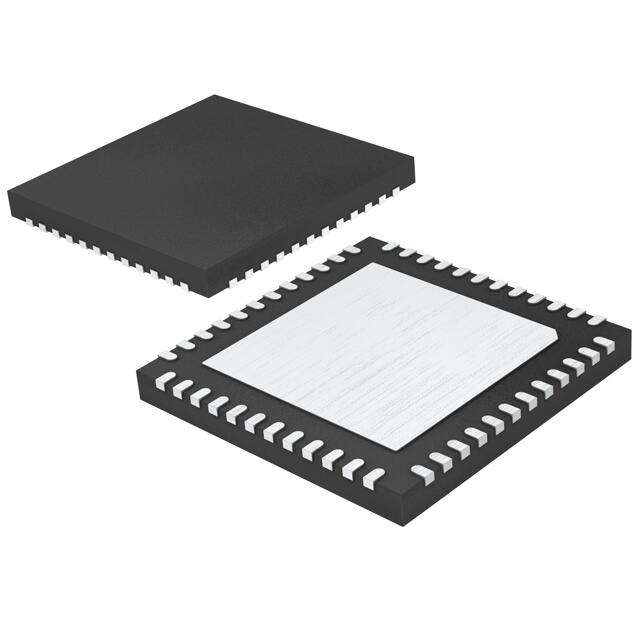


 工商网监
湘ICP备2023018690号
工商网监
湘ICP备2023018690号
