LTC6373
36V Fully-Differential Programmable-Gain
Instrumentation Amplifier with 25pA Input Bias Current
FEATURES
DESCRIPTION
Pin-Programmable Gains:
G = 0.25, 0.5, 1, 2, 4, 8, 16V/V + Shutdown
n Fully Differential Outputs
n Gain Error: 0.012% (Max)
n Gain Error Drift: 1ppm/°C (Max)
n CMRR: 103dB (Min), G = 16
n Input Bias Current: 25pA (Max)
n Input Offset Voltage: 92μV (Max), G = 16
n Input Offset Voltage Drift: 1.7μV/°C (Max), G = 16
n –3dB Bandwidth: 4MHz, G = 16
n Input Noise Density: 8nV/√Hz, G = 16
n Slew Rate: 12V/μs, G = 16
n Adjustable Output Common Mode Voltage
n Quiescent Supply Current: 4.4mA
n Supply Voltage Range: ±4.5V to ±18V
n –40°C to 125°C Specified Temperature Range
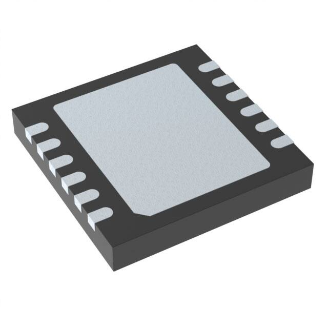
n Small 12-Lead 4mm × 4mm DFN (LFCSP) Package
The LTC®6373 is a precision instrumentation amplifier
with fully differential outputs which includes a closelymatched internal resistor network to achieve excellent
CMRR, offset voltage, gain error, gain drift, and gain nonlinearity. The user can easily program the gain to one
of seven available settings through a 3-bit parallel interface (A2 to A0). The 8th state puts the part in shutdown
which reduces the current consumption to 220μA. Unlike
a conventional voltage feedback amplifier, the LTC6373
maintains nearly the same bandwidth across all its gain
settings.
n
The LTC6373 features fully differential outputs to drive
high performance, differential-input ADCs. The output
common mode voltage is independently adjustable via
the VOCM pin. The combination of high impedance inputs,
DC precision, low noise, low distortion, and high-speed
differential ADC drive makes the LTC6373 an ideal candidate for optimizing data acquisition systems.
APPLICATIONS
The LTC6373 is available in a 12-lead 4mm × 4mm DFN
(LFCSP) package and is fully specified over the −40°C to
125°C temperature range.
Data Acquisition Systems
n Biomedical Instrumentation
n Test and Measurement Equipment
n Differential ADC Drivers
n Single-Ended-to-Differential Conversion
n Multiplexed Applications
n
All registered trademarks and trademarks are the property of their respective owners.
TYPICAL APPLICATION
vs Frequency
Gain vsGain
Frequency
36
Interfacing a 40VP-P Ground-Referenced Differential Input Signal to a 5V ADC
10V
V+OUT
A2
A1
A0
–10V
V+IN
V–
CAP
DGND
VOCM
+
10V
–10V
0V
–
2.5V
V–IN
LTC6373
180pF
180pF
887Ω
IN+
887Ω
5V
IN–
180pF
0V
–15V
18
5V
G = 0.25
V+
24
5V
1.8V
VREF
VDD
AD4020
SAR ADC
GAIN (dB)
15V
RL = 2kΩ
30
20-BIT
0.6Msps
GND
MEASURED SIGNAL CHAIN PERFORMANCE:
INPUT: fIN =1kHz, –0.5dBFS
SNR: 96.5dB
6373 TA01a
THD: –122dB
12
6
0
–6
–12
–18
–24
0.01
0.1
G = 16
G=8
G=4
1
10
FREQUENCY (MHz)
G=2
G=1
100
6373 TA01b
G = 0.5
G = 0.25
Rev. 0
Document Feedback
For more information www.analog.com
1
�LTC6373
ABSOLUTE MAXIMUM RATINGS
PIN CONFIGURATION
(Note 1)
Supply Voltages
V+...................................................... V– to (V– + 40V)
V+OUT................................................ V– to (V+ + 0.3V)
VOCM..................................(V– – 0.3V) to (V+OUT + 0.3V)
A0, A1, A2, DGND.................... (V– – 0.3V) to (V+ + 0.3V)
+IN, –IN
Common Mode................... (V– – 0.3V) to (V+ + 0.3V)
Differential...........................................................±20V
Output Current (+OUT, –OUT) (Note 2)............ 40mARMS
Output Short-Circuit Duration (+OUT, –OUT)
(Note 3)................................................Thermally Limited
Operating and Specified Temperature Range (Notes 4, 5)
LTC6373I..............................................–40°C to 85°C
LTC6373H........................................... –40°C to 125°C
Maximum Junction Temperature........................... 150°C
Storage Temperature Range................... –65°C to 150°C
TOP VIEW
12 +IN
–IN
1
A0
2
A1
3
V+
4
V+OUT
5
8 VOCM
+OUT
6
7 –OUT
11 A2
13
V–
10 DGND
9 CAP
DFM PACKAGE
12-LEAD (4mm × 4mm) PLASTIC DFN
TJMAX = 150°C, θJA = 43°C/W, θJC = 3.4°C/W
EXPOSED PAD (PIN 13) IS V–, MUST BE SOLDERED TO PCB
ORDER INFORMATION
TUBE
TAPE AND REEL
PART MARKING* PACKAGE DESCRIPTION
TEMPERATURE RANGE
LTC6373IDFM#PBF
LTC6373IDFM#TRPBF
6373
12-Lead (4mm × 4mm) Plastic DFN, Side Solderable –40°C to 85°C
LTC6373HDFM#PBF
LTC6373HDFM#TRPBF
6373
12-Lead (4mm × 4mm) Plastic DFN, Side Solderable –40°C to 125°C
Contact the factory for parts specified with wider operating temperature ranges. *The temperature grade is identified by a label on the shipping container.
Tape and reel specifications. Some packages are available in 500 unit reels through designated sales channels with #TRMPBF suffix.
Rev. 0
2
For more information www.analog.com
�LTC6373
ELECTRICAL CHARACTERISTICS
The l denotes the specifications which apply over the full operating
temperature range, otherwise specifications and all typical values are at TA = 25°C. V+ = V+OUT = 15V, V– = –15V, VICM = VOCM = DGND =
0V, G = 1 (A2 = 5V, A1 = A0 = 0V). VS is defined as (V+ – V–). VICM is defined as (V+IN + V–IN)/2. VOUTCM is defined as (V+OUT + V–OUT)/2.
VOUTDIFF is defined as (V+OUT – V–OUT).
SYMBOL
PARAMETER
CONDITIONS
MIN
GDIFF
Differential Gain Range
G = 16, 8, 4, 2, 1, 0.5, 0.25
0.25
∆GDIFF
Differential Gain Error (Note 11)
G = 4, 2, 1, 0.5, 0.25
G = 4, 2, 1, 0.5, 0.25
l
G = 16, 8
G = 16, 8
l
∆GDIFF/∆T
Differential Gain Drift (Note 6)
GNL
Differential Gain Nonlinearity (Note 11)
l
VOUTDIFF = 40VP-P
TYP
∆VOSDIFF/∆T
V/V
0.002
0.012
0.02
%
%
0.003
0.015
0.023
%
%
0.25
1
ppm/°C
1
3
10
ppm
ppm
10 + 40/G
80 + 192/G
250 + 400/G
1120 + 1120/G
1.5 + 2.5/G
5 + 5.5/G
Differential Offset Voltage (Input Referred)
(Note 7)
G = 16, 8, 4, 2, 1, 0.5, 0.25
TA = –40°C to 85°C
TA = –40°C to 125°C
l
l
Differential Offset Voltage Drift
(Input Referred) (Note 6)
G = 16, 8, 4, 2, 1, 0.5, 0.25
TA = –40°C to 85°C
TA = –40°C to 125°C
l
l
0.3 + 0.5/G
2 + 1.5/G
l
10 + 15/G
Differential Offset Voltage Hysteresis (Input G = 16, 8, 4, 2, 1, 0.5, 0.25
Referred) (Note 12)
IB
IOS
Input Bias Current (Notes 7, 8)
Input Offset Current (Notes 7, 8)
Active
TA = –40°C to 85°C
TA = –40°C to 125°C
2
l
l
Shutdown (A2 = A1 = A0 = 5V)
20
Active
TA = –40°C to 85°C
TA = –40°C to 125°C
2
l
l
Shutdown (A2 = A1 = A0 = 5V)
en
in
Differential Input Voltage Noise Density
f = 10kHz
G = 16
G = 8
G = 4
G = 2
G = 1
G = 0.5
G = 0.25
Differential Input Voltage Noise
0.1Hz to10Hz
G = 16
G = 8
G = 4
G = 2
G = 1
G = 0.5
G = 0.25
Input Current Noise Density
f = 10kHz
Input Current Noise
0.1Hz to 10Hz
enVOCM
Common Mode Voltage Noise Density
f = 10kHz
RIN
Input Resistance
Differential Mode
Common Mode
CIN
Input Capacitance
VINR
Input Voltage Range
25
50
500
pA
pA
pA
pA
pA
pA
pA
8
8.4
9.5
12.2
18.7
26.4
41
nV/√Hz
nV/√Hz
nV/√Hz
nV/√Hz
nV/√Hz
nV/√Hz
nV/√Hz
1.1
1.2
1.3
1.5
1.8
2.4
4.2
μVP-P
μVP-P
μVP-P
μVP-P
μVP-P
μVP-P
μVP-P
1
fA/√Hz
100
fAP-P
24
nV/√Hz
Ω
Ω
15
l
μV/°C
μV/°C
pA
25
40
100
5×10¹²
5×10¹²
V– + 3
–
V + 3.25
μV
μV
μV
μV
5
UNITS
16
l
VOSDIFF
MAX
pF
V+ – 3
V+ – 3
V
V
Rev. 0
For more information www.analog.com
3
�LTC6373
ELECTRICAL CHARACTERISTICS
The l denotes the specifications which apply over the full operating
temperature range, otherwise specifications and all typical values are at TA = 25°C. V+ = V+OUT = 15V, V– = –15V, VICM = VOCM = DGND =
0V, G = 1 (A2 = 5V, A1 = A0 = 0V). VS is defined as (V+ – V–). VICM is defined as (V+IN + V–IN)/2. VOUTCM is defined as (V+OUT + V–OUT)/2.
VOUTDIFF is defined as (V+OUT – V–OUT).
SYMBOL
PARAMETER
CONDITIONS
CMRR
(Note 9)
Input Common Mode Rejection Ratio
(Input Referred) ∆VICM/∆VOSDIFF
DC to 60Hz, 1kΩ Source
Imbalance, VICM = ±10V
G = 16
G = 16
MIN
TYP
MAX
UNITS
103
98
119
l
dB
dB
G = 8
G = 8
100
98
113
l
dB
dB
G = 4
G = 4
94
92
107
l
dB
dB
G = 2
G = 2
88
86
101
l
dB
dB
G = 1
G = 1
82
80
95
l
dB
dB
G = 0.5
G = 0.5
83
80
95
l
dB
dB
G = 0.25
G = 0.25
80
75
95
l
dB
dB
CMRRIO
(Note 9)
Output Common Mode Rejection Ratio
(Input Referred) ∆VOCM/∆VOSDIFF
VOCM = ±13V
l
75
95
dB
PSRR
(Note 10)
Differential Power Supply Rejection
Ratio (∆VS/∆VOSDIFF)
VS = ±4.5V to ±18V
G = 16
G = 8
G = 4
G = 2
G = 1
G = 0.5
G = 0.25
l
l
l
l
l
l
l
105
102
102
100
98
95
92
142
139
136
133
130
125
120
dB
dB
dB
dB
dB
dB
dB
PSRRCM
(Note 10)
Output Common Mode Power Supply
Rejection Ratio (∆VS/∆VOSCM)
VS = ±4.5V to ±18V
l
110
135
dB
VOUT
Output Voltage, High, Either Output Pin
IL = 0mA, VS = ±4.5V
IL = –5mA, VS = ±4.5V
l V+OUT – 0.6 V+OUT – 0.3
l V+OUT –1.1 V+OUT – 0.7
V
V
IL = 0mA, VS = ±15V
IL = –5mA, VS = ±15V
l V+OUT – 1.8 V+OUT – 1.1
l V+OUT – 1.9 V+OUT – 1.3
V
V
IL = 0mA, VS = ±4.5V
IL = 5mA, VS = ±4.5V
l
l
V– + 0.3
V– + 0.6
V– + 0.6
V– + 1
V
V
IL = 0mA, VS = ±15V
IL = 5mA, VS = ±15V
l
l
V– + 1.1
V– + 1.2
V– + 1.8
V– + 1.9
V
V
Output Voltage, Low, Either Output Pin
Output Short-Circuit Current, Either Output VS = ±4.5V
Pin, Sinking
VS = ±15V
l
l
27
35
39
47
mA
mA
Output Short-Circuit Current, Either Output VS = ±4.5V
VS = ±15V
Pin, Sourcing
l
l
23
29
33
38
mA
mA
GCM
Common Mode Gain (∆VOUTCM/∆VOCM)
VS = ±4.5V, VOCM = ±3V
VS = ±15V, VOCM = ±13V
l
l
1
1
V/V
V/V
∆GCM
Common Mode Gain Error
100 × (GCM – 1)
VS = ±4.5V, VOCM = ±3V
VS = ±15V, VOCM = ±13V
l
l
0.05
0.05
0.1
0.1
%
%
BAL
Output Balance (∆VOUTCM/∆VOUTDIFF)
VOUTDIFF = ±10V
Single-Ended Input
Differential Input
l
l
–80
–90
–70
–75
dB
dB
1
40
50
mV
mV
ISC
VOSCM
Common Mode Offset Voltage
(VOUTCM – VOCM)
l
Rev. 0
4
For more information www.analog.com
�LTC6373
ELECTRICAL CHARACTERISTICS
The l denotes the specifications which apply over the full operating
temperature range, otherwise specifications and all typical values are at TA = 25°C. V+ = V+OUT = 15V, V– = –15V, VICM = VOCM = DGND =
0V, G = 1 (A2 = 5V, A1 = A0 = 0V). VS is defined as (V+ – V–). VICM is defined as (V+IN + V–IN)/2. VOUTCM is defined as (V+OUT + V–OUT)/2.
VOUTDIFF is defined as (V+OUT – V–OUT).
SYMBOL
PARAMETER
CONDITIONS
VOUTCMR
Voltage Range for the VOCM Pin
(Guaranteed by ∆GCM)
VS = ±4.5V
VS = ±15V
l
l
MIN
VOCM
Self-Biased Voltage at the VOCM Pin
VOCM Not Connected
l
RINVOCM
Input Resistance, VOCM Pin
VDGND
Voltage Range for the DGND Pin
UNITS
V
V
(V+OUT +
V–)/2 + 0.1
V
(V+OUT +
V–)/2
l
1.9
2.3
2.7
l
V–
0
V+ – 2.5
V
–4
DGND Pin Current
DGND = 5V, A2 = A1 = A0 = 15V
l
–7
VIL
Digital Input (A2/A1/A0) Logic Low
Referred to DGND
l
DGND
Digital Input (A2/A1/A0) Logic High
MAX
V+OUT – 1.5
V+OUT – 2
(V+OUT +
V–)/2 – 0.1
IDGND
VIH
TYP
V– + 1.5
V– + 2
Referred to DGND
l DGND + 1.5
l
8
MΩ
–1
µA
DGND + 0.6
V
V+
V
IA2/A1/A0
Digital Input (A2/A1/A0) Pin Current
A2/A1/A0 = 5V
f–3dB
–3dB Bandwidth
SR
Slew Rate
G = 16, VOUTDIFF = 40VP-P Step, RL = 2kΩ l
ts
Settling Time
G = 16, VOUTDIFF = 8VP-P Step, RL = 1kΩ
0.1%
0.01%
0.0015% (16-Bit)
4ppm (18-Bit)
2.1
2.25
2.4
2.7
µs
µs
µs
µs
THD
Total Harmonic Distortion
G = 1, VOUTDIFF = 10VP-P, RL = 2kΩ
f = 1kHz
f = 10kHz
–115
–110
dB
dB
tON
Turn-On Time
10
µs
tOFF
Turn-Off Time
5
µs
Gain Switching Time
5
µs
G = 16
G=8
G=4
G=2
G=1
G = 0.5
G = 0.25
VS
Supply Voltage Range
Guaranteed by PSRR
IS
Supply Current
Active
l
7.5
l
µA
MHz
MHz
MHz
MHz
MHz
MHz
MHz
12
V/µs
9
36
V
4.4
4.75
5.25
mA
mA
220
600
µA
l
Shutdown (A2 = A1 = A0 = 5V)
12
4
5.5
6
6.5
6.5
7
7.5
Rev. 0
For more information www.analog.com
5
�LTC6373
ELECTRICAL CHARACTERISTICS
Note 1: Stresses beyond those listed under Absolute Maximum Ratings
may cause permanent damage to the device. Exposure to any Absolute
Maximum Rating condition for extended periods may affect device
reliability and lifetime.
Note 2: The LTC6373 is capable of producing peak output currents in
excess of 40mA. Current density limitations within the IC require the
continuous RMS current supplied by the output (sourcing or sinking)
over the operating lifetime of the part be limited to under 40mA (Absolute
Maximum).
Note 3: A heat sink may be required to keep the junction temperature
below absolute maximum when the output is shorted indefinitely.
Note 4: The LTC6373I is guaranteed functional over the operating
temperature range of –40°C to 85°C. The LTC6373H is guaranteed
functional over the operating temperature range of –40°C to 125°C.
Note 5: The LTC6373I is guaranteed to meet specified performance
from –40°C to 85°C. The LTC6373H is guaranteed to meet specified
performance from –40°C to 125°C.
Note 6: Guaranteed by design.
Note 7: ESD (Electrostatic Discharge) sensitive device. ESD protection
devices are used extensively internal to the LTC6373; however, high
electrostatic discharge can damage or degrade the device. Use proper ESD
handling precautions.
Note 8: Input bias current is defined as the maximum of the input currents
flowing into either of the input pins (–IN and +IN). Input Offset current is
defined as the difference between the input currents (IOS = IB+ – IB–).
Note 9: Input CMRR (CMRR) is defined as the ratio of the change in
the input common mode voltage at the pins +IN or –IN to the change
in differential input referred offset voltage. Output CMRR (CMRRIO) is
defined as the ratio of the change in the voltage at the VOCM pin to the
change in differential input referred offset voltage.
Note 10: Differential power supply rejection ratio (PSRR) is defined as
the ratio of the change in supply voltage to the change in differential
input referred offset voltage. Common mode power supply rejection ratio
(PSRRCM) is defined as the ratio of the change in supply voltage to the
change in the common mode offset voltage.
Note 11: This parameter is measured in a high speed automatic tester
that does not measure the thermal effects with longer time constants. The
magnitude of these thermal effects are dependent on the package used,
PCB layout, heat sinking and air flow conditions.
Note 12: Hysteresis in output voltage is created by mechanical stress
that differs depending on whether the IC was previously at a higher or
lower temperature. Output voltage is always measured at 25°C, but
the IC is cycled to the hot or cold temperature limit before successive
measurements. For instruments that are stored in well controlled
temperatures (within 20 or 30 degrees of operational temperature),
hysteresis is usually not a significant error source. Typical Hysteresis is
the worst case of differential offset measured between 25°C to -40°C to
25°C thermal cycle and 25°C to 125°C to 25°C thermal cycle.
Rev. 0
6
For more information www.analog.com
�LTC6373
TYPICAL PERFORMANCE CHARACTERISTICS
V+ = V+OUT = 15V, V– = –15V, VICM = VOCM = 0V, TA = 25°C, G = 1, unless otherwise noted.
30
25
20
15
10
30
25
20
15
10
G = 0.25
TA = 25°C
~1500 UNITS
25
20
15
10
5
5
0
–100 –80 –60 –40 –20 0 20 40 60 80 100
DIFFERENTIAL RTI OFFSET VOLTAGE (µV)
0
–250 –200–150–100 –50 0 50 100 150 200 250
DIFFERENTIAL RTI OFFSET VOLTAGE (µV)
0
–750 –600–450–300–150 0 150 300 450 600 750
DIFFERENTIAL RTI OFFSET VOLTAGE (µV)
20
Typical Distribution of Differential
RTI Offset Voltage Drift
25
G = 16
TA = –40°C to 85°C
97 UNITS
PERCENTAGE OF UNITS (%)
25
15
10
5
20
25
G=1
TA = –40°C to 85°C
97 UNITS
15
10
5
6373 G05
6373 G04
10
5
Typical Distribution of CMRR
25
25
PERCENTAGE OF UNITS (%)
G = 16
TA = 25°C
VICM = ±10V
20 ~1500 UNITS
15
10
5
4
15
6373 G06
5
6373 G07
6
20
Typical Distribution of CMRR
25
G=1
TA = 25°C
VICM = ±10V
~1500 UNITS
PERCENTAGE OF UNITS (%)
Typical Distribution of CMRR
20
G = 0.25
TA = –40°C to 85°C
97 UNITS
0
–10 –8 –6 –4 –2 0 2 4 6 8 10
DIFFERENTIAL RTI OFFSET VOLTAGE DRIFT (µV/°C)
–5 –4 –3 –2 –1 0 1 2 3 4 5
DIFFERENTIAL RTI OFFSET VOLTAGE DRIFT (µV/°C)
–2 –1.6 –1.2 –0.8 –0.4 0 0.4 0.8 1.2 1.6 2
DIFFERENTIAL RTI OFFSET VOLTAGE DRIFT (µV/°C)
–6 –5 –4 –3 –2 –1 0 1 2 3
CMRR (µV/V = ppm)
Typical
Typical Distribution
Distribution of
of Differential
Differential
RTI
Offset
Voltage
Drift
RTI Offset Voltage Drift
0
0
0
6373 G03
6373 G02
Typical
Typical Distribution
Distribution of
of Differential
Differential
RTI
RTI Offset
Offset Voltage
Voltage Drift
Drift
PERCENTAGE OF UNITS (%)
35
G=1
TA = 25°C
~1500 UNITS
5
6373 G01
PERCENTAGE OF UNITS (%)
Typical
Typical Distribution
Distribution of
of Differential
Differential
RTI
RTI Offset
Offset Voltage
Voltage
PERCENTAGE OF UNITS (%)
PERCENTAGE OF UNITS (%)
30
35
G = 16
TA = 25°C
~1500 UNITS
PERCENTAGE OF UNITS (%)
35
Typical
Typical Distribution
Distribution of
of Differential
Differential
RTI
RTI Offset
Offset Voltage
Voltage
PERCENTAGE OF UNITS (%)
Typical Distribution of Differential
RTI Offset Voltage
15
10
5
0
–100 –80 –60 –40 –20 0 20 40 60 80 100
CMRR (µV/V = ppm)
6373 G08
20
G = 0.25
TA = 25°C
VICM = ±10V
~1500 UNITS
15
10
5
0
–100 –80 –60 –40 –20 0 20 40 60 80 100
CMRR (µV/V = ppm)
6373 G09
Rev. 0
For more information www.analog.com
7
�LTC6373
TYPICAL PERFORMANCE CHARACTERISTICS
V+ = V+OUT = 15V, V– = –15V, VICM = VOCM = 0V, TA = 25°C, G = 1, unless otherwise noted.
Typical Distribution of Differential
PSRR
45
G = 16
40 TA = 25°C
VS = ±4.5V TO ±18V
35 ~1500 UNITS
30
25
20
15
10
35
25
20
15
10
5
0
–0.6
0
–1.2
–0.2
0
0.2
PSRR (µV/V = ppm)
0.4
0.6
–0.8
–0.4
0
0.4
PSRR (µV/V = ppm)
0.8
1.2
100
20
15
10
0
–2.4
–1.6
–0.8
0
0.8
PSRR (µV/V = ppm)
70
60
50
40
30
20
10
80
70
60
50
40
30
20
10
0
2
0
4 6 8 10 12 14 16 18 20
INPUT BIAS CURRENT (pA)
0
2
4 6 8 10 12 14 16 18 20
INPUT OFFSET CURRENT (pA)
6373 G14
Typical Distribution
Distribution of
of Differential
Differential
Typical
Gain
Nonlinearity
Gain Nonlinearity
Typical
Typical Distribution
Distribution of
of Differential
Differential
Gain
Gain Error
Error
80
TA = 25°C
~1500 UNITS
TA = 25°C
~1500 UNITS
70
20
PERCENTAGE OF UNITS (%)
PERCENTAGE OF UNITS (%)
2.4
6373 G12
6373 G13
25
1.6
TA = 25°C
~1500 UNITS
90
PERCENTAGE OF UNITS (%)
PERCENTAGE OF UNITS (%)
25
Typical
Typical Distribution
Distribution of
of Input
Input
Offset
Offset Current
Current
TA = 25°C
~1500 UNITS
80
0
30
6373 G11
Typical Distribution of Input Bias
Current
Bias Current
90
35
5
6373 G10
100
G = 0.25
TA = 25°C
VS = ±4.5V TO ±18V
~1500 UNITS
40
30
5
–0.4
45
G=1
TA = 25°C
VS = ±4.5V TO ±18V
~1500 UNITS
40
PERCENTAGE OF UNITS (%)
PERCENTAGE OF UNITS (%)
45
Typical Distribution of Differential
PSRR
PERCENTAGE OF UNITS (%)
Typical Distribution
Distribution of
of Differential
Differential
Typical
PSRR
PSRR
15
10
5
60
50
40
30
20
10
0
–100 –80 –60 –40 –20 0 20 40 60 80 100
GAIN ERROR (ppm)
0
0
6373 G15
0.5
1
1.5
2
2.5
GAIN NONLINEARITY (ppm)
3
6373 G16
Rev. 0
8
For more information www.analog.com
�LTC6373
TYPICAL PERFORMANCE CHARACTERISTICS
V+ = V+OUT = 15V, V– = –15V, VICM = VOCM = 0V, TA = 25°C, G = 1, unless otherwise noted.
DifferentialGain
GainNonlinearity
Nonlinearity vs
Differential
Output
Voltage
vs
Output
Voltage
0
–5
–10
–15
–20
–20 –15 –10
NO RL
RL = 10kΩ
RL = 2kΩ
RL = 1kΩ
100
100
80
80
60
60
40
40
20
0
–20
–40
–80
–5
0
5
VOUTDIFF (V)
10
15
20
0
25
50
75
TEMPERATURE (°C)
100
125
40
CMRR (µV/V = ppm)
60
12
6
0
–6
20
0
–20
–40
–60
–12
–80
–18
1
10
FREQUENCY (MHz)
100
–100
–50
–25
6373 G20
G=2
G=1
G = 0.5
G = 0.25
G = 16
G=8
G=4
0
25
50
75
TEMPERATURE (°C)
G=2
G=1
100
125
G=2
G=1
100
125
6373 G19
G = 0.5
G = 0.25
100
1k
10k
FREQUENCY (Hz)
G = 16
G=8
G=4
G=2
G=1
100k
1M
6373 G22
G = 0.5
G = 0.25
Positive PSRR vs Frequency, RTI
140
130
120
100
110
90
100
PSRR (dB)
110
80
70
60
90
80
70
50
60
NO SOURCE IMBALANCE
1kΩ SOURCE IMBALANCE
5kΩ SOURCE IMBALANCE
10kΩ SOURCE IMBALANCE
40
30
20
0.1
10
G = 0.5
G = 0.25
G = 16
120
130
124
118
112
106
100
94
88
82
76
70
64
58
52
46
40
6373 G21
CMRR vs Frequency With Source
Imbalance
Source Imbalance
130
0
25
50
75
TEMPERATURE (°C)
CMRR
vsFrequency
Frequency
CMRR vs
TYPICAL UNIT
80
–25
G = 16
G=8
G=4
CMRR
vsTemperature
Temperature
CMRR vs
100
18
CMRR (dB)
GAIN (dB)
–25
–100
–50
6373 G18
24
G = 16
G=8
G=4
–40
–80
5 UNITS
G = 16
6373 G17
RL = 2kΩ
0.1
0
–20
–60
–100
–50
Gain
vsFrequency
Frequency
Gain vs
30
TYPICAL UNIT
20
–60
36
–24
0.01
GAIN ERROR (ppm)
10
5
Differential Gain Error vs
Temperature
CMRR (dB)
15
LINEAR FIT FOR –20V ≤ VOUTDIFF ≤ 20V
DIFFERENTIAL INPUTS
GAIN ERROR (ppm)
GAIN NONLINEARITY (µV/V = ppm)
20
Differential Gain Error vs
Temperature
Temperature
1
10
50
40
100 1k 10k 100k
FREQUENCY (Hz)
1M
10
6373 G23
For more information www.analog.com
100
1k
10k
FREQUENCY (Hz)
100k
1M
6373 G24
G = 16
G=8
G=4
G=2
G=1
G = 0.5
G = 0.25
Rev. 0
9
�LTC6373
TYPICAL PERFORMANCE CHARACTERISTICS
V+ = V+OUT = 15V, V– = –15V, VICM = VOCM = 0V, TA = 25°C, G = 1, unless otherwise noted.
140
20
130
19
120
18
SLEW RATE (V/µs)
PSRR (dB)
110
100
90
80
70
60
3
G = 16
VOUTDIFF = 40VP-P STEP
RL = 2kΩ
SLEW RATE MEASURED 10% TO 90%
17
16
15
14
13
12
50
40
Long Term Differential RTI Offset
Voltage Drift
Slew Rate
Ratevs
vsTemperature
Temperature
Slew
CHANGE IN
DIFFERENTIAL RTI OFFSET VOLTAGE (µV)
NegativePSRR
PSRRvsvsFrequency,
Frequency,
Negative
RTIRTI
11
10
100
1k
10k
FREQUENCY (Hz)
100k
1M
10
–50
6373 G25
G = 16
G=8
G=4
G=2
G=1
–25
0
25
50
75
TEMPERATURE (°C)
100
125
2.5
2
1.5
1
0.5
0
–0.5
–1
–1.5
–2
–3
6373 G26
G = 0.5
G = 0.25
G = 16
6 UNITS, SOLDERED TO PCB
–2.5
0
250 500 750 1000 1250 1500 1750 2000
TIME (HOURS)
6373 G27
Input Referred Voltage Noise
Density
vsFrequency
Frequency
Density vs
Input Referred 0.1Hz to 10Hz
Voltage Noise (G = 16)
Input Referred 0.1Hz to 10Hz
Voltage Noise (G = 8)
VOLTAGE NOISE (200nV/DIV)
VOLTAGE NOISE (200nV/DIV)
100
10
1
0.1
1
10
100
1k
FREQUENCY (Hz)
10k
100k
G = 16
G=8
G=4
G=2
G=1
TIME (1s/DIV)
TIME (1s/DIV)
6373 G28
G = 0.5
G = 0.25
6373 G30
6373 G29
Input Referred 0.1Hz to 10Hz
Voltage Noise (G = 2)
Input Referred 0.1Hz to 10Hz
Voltage Noise (G = 1)
VOLTAGE NOISE (200nV/DIV)
VOLTAGE NOISE (200nV/DIV)
Input Referred 0.1Hz to 10Hz
Voltage Noise (G = 4)
VOLTAGE NOISE (200nV/DIV)
VOLTAGE NOISE DENSITY (nV/√Hz)
1000
TIME (1s/DIV)
6373 G31
TIME (1s/DIV)
TIME (1s/DIV)
6373 G32
6373 G33
Rev. 0
10
For more information www.analog.com
�LTC6373
TYPICAL PERFORMANCE CHARACTERISTICS
V+ = V+OUT = 15V, V– = –15V, VICM = VOCM = 0V, TA = 25°C, G = 1, unless otherwise noted.
Input Referred 0.1Hz to 10Hz
Voltage Noise (G = 0.5)
Input Referred 0.1Hz to 10Hz
Voltage Noise (G = 0.25)
DGND Pin Current vs DGND Pin
Voltage
10
0
DGND PIN CURRENT (µA)
VOLTAGE NOISE (500nV/DIV)
VOLTAGE NOISE (500nV/DIV)
A2 = A1 = A0 = 15V
–10
–20
–30
–40°C
25°C
85°C
125°C
–40
–50
–15 –12.5 –10 –7.5 –5 –2.5 0 2.5 5 7.5 10 12.5
DGND VOLTAGE (V)
TIME (1s/DIV)
TIME (1s/DIV)
6373 G35
6373 G34
6373 G36
A0 Digital Input Pin Current vs
A0 Digital Input Pin Voltage
60
DGND = A2 = A1 = 0V
40
30
20
–40°C
25°C
85°C
125°C
10
0
30
20
–40°C
25°C
85°C
125°C
10
0
0 1 2 3 4 5 6 7 8 9 10 11 12 13 14 15
A0 VOLTAGE (V)
40
30
20
0
0 1 2 3 4 5 6 7 8 9 10 11 12 13 14 15
A1 VOLTAGE (V)
Shutdown Supply Current vs
Temperature
300
4.9
4.5
280
4.8
4.0
260
4.5
4.4
4.3
4.2
VS = 9V
VS = 30V
4.1
4.0
–50
–25
0
25
50
75
TEMPERATURE (°C)
100
3.5
3.0
2.5
2.0
1.5
–40°C
25°C
85°C
125°C
1.0
0.5
125
6373 G40
TOTAL SUPPLY CURRENT (µA)
5.0
TOTAL SUPPLY CURRENT (mA)
5.0
4.6
0
0
5
10 15 20 25 30
SUPPLY VOLTAGE (V)
35
0 1 2 3 4 5 6 7 8 9 10 11 12 13 14 15
A2 VOLTAGE (V)
6373 G39
Supply Current vs Supply Voltage
4.7
–40°C
25°C
85°C
125°C
10
6373 G38
Supply Current vs Temperature
DGND = A1 = A0 = 0V
50
40
6373 G37
TOTAL SUPPLY CURRENT (mA)
60
DGND = A2 = A0 = 0V
50
A1 PIN CURRENT (µA)
A0 PIN CURRENT (µA)
50
A2 Digital Input Pin Current vs
A2 Digital Input Pin Voltage
A2 PIN CURRENT (µA)
60
A1 Digital Input Pin Current vs
A1 Digital Input Pin Voltage
240
220
200
180
160
140
VS = 9V
VS = 30V
120
40
6373 G41
100
–50
–25
0
25
50
75
TEMPERATURE (°C)
100
125
6373 G42
Rev. 0
For more information www.analog.com
11
�LTC6373
TYPICAL PERFORMANCE CHARACTERISTICS
V+ = V+OUT = 15V, V– = –15V, VICM = VOCM = 0V, TA = 25°C, G = 1, unless otherwise noted.
Supply Current vs Digital Input
(A2/A1/A0) Pin Voltage
300
5.0
DGND = 0V
TOTAL SUPPLY CURRENT (mA)
200
150
100
–40°C
25°C
85°C
125°C
50
0
0
5
10 15 20 25 30
SUPPLY VOLTAGE (V)
35
–40°C
25°C
85°C
125°C
4.0
3.5
3.0
2.5
2.0
1.5
1.0
0.5
0
40
INPUT BIAS AND OFFSET CURRENTS (pA)
INPUT BIAS AND OFFSET CURRENTS (|pA|)
DIRECTION OF THE CURRENT
IS OUT OF THE PIN
10
1
0.1
–50
IB (+IN)
IB (–IN)
IOS
–25
0
25
50
75
TEMPERATURE (°C)
100
125
1
0.1
–50
40
15
30
20
10
0
–10
–20
–30
IB (+IN)
IB (–IN)
IOS
–40
–50
–15
–10
–5
0
5
10
INPUT COMMON MODE VOLTAGE (V)
10
–15
15
IB (+IN)
IB (–IN)
–20
–30
–20
–10
0
10
20
30
INPUT DIFFERENTIAL VOLTAGE, V+IN – V –IN (V)
6373 G48
Large Signal Step Response
VOLTAGE (5V/DIV)
VOLTAGE (5V/DIV)
DIFFERENTIAL RTI OFFSET VOLTAGE (µV)
G=1
VINDIFF = 20VP-P
RL = 2kΩ
400
G = 16
VINDIFF = 2.5VP-P
RL = 2kΩ
–600
6373 G49
G = 0.5
G = 0.25
FAULT CONDITION
(OVER DRIVEN INPUT)
–10
600
G=2
G=1
G = 16
–5
–OUT
G = 16
G=8
G=4
125
0
Large Signal Step Response
800
–800
NORMALIZED AT VICM = 0V
–1000
–15 –12 –9 –6 –3 0 3 6 9 12 15
INPUT COMMON MODE VOLTAGE (V)
100
5
1000
–400
0
25
50
75
TEMPERATURE (°C)
6373 G47
Differential RTI Offset Voltage vs
0
–25
Input Bias Current vs Input
Differential Voltage
20
Input
Common
vs
Input
CommonMode
Mode Voltage
Voltage
–200
IB (+IN)
IB (–IN)
IOS
6373 G45
50
6373 G46
200
DIRECTION OF THE CURRENT
IS OUT OF THE PIN
10
Input Bias Current and Offset Current
vs Input Common Mode Voltage
VS = 9V
VS = 30V
6373 G44
Input Bias Current and Offset
Current vs Temperature
100
100
0 1 2 3 4 5 6 7 8 9 10 11 12 13 14 15
A2 = A1 = A0 VOLTAGE (V)
6373 G43
1k
1k
INPUT BIAS CURRENT (mA)
TOTAL SUPPLY CURRENT (µA)
4.5
250
Input Bias Current and Offset
Current vs Temperature
INPUT BIAS AND OFFSET CURRENTS (|pA|)
Shutdown Supply Current vs
Supply Voltage
–OUT
+OUT
+OUT
TIME (2µs/DIV)
6373 G50
TIME (2µs/DIV)
6373 G51
Rev. 0
12
For more information www.analog.com
�LTC6373
TYPICAL PERFORMANCE CHARACTERISTICS
V+ = V+OUT = 15V, V– = –15V, VICM = VOCM = 0V, TA = 25°C, G = 1, unless otherwise noted.
Large Signal Step Response
Small Signal Step Response
G = 0.25
VINDIFF = 20VP-P
RL = 2kΩ
G=1
VINDIFF = 200mVP-P
RL = 2kΩ
+OUT
VOLTAGE (50mV/DIV)
VOLTAGE (50mV/DIV)
–OUT
VOLTAGE (0.5V/DIV)
Small Signal Step Response
G = 16
VINDIFF = 12.5mVP-P
RL = 2kΩ
–OUT
+OUT
VOUTDIFF = 200mVP-P
90 RL = 2kΩ
60
50
40
30
0
20
40
60
80
CAPACITIVE LOAD, CL (pF)
G = 16
G=8
G=4
6373 G55
–2
G=2
G=1
10.0
7.5
7.5
5.0
2.5
0
25°C
–40°C
85°C
125°C
–0.1
–0.2
VOUTDIFF
–0.3
–8
–0.5
100
0
0.5
1
1.5
TIME (µs)
2
–0.4
2.5
6373 G57
6373 G56
G = 0.5
G = 0.25
High Output Voltage Swing vs
Supply Voltage
3.0
G=2
HIGH OUTPUT VOLTAGE SWING,
RELATIVE TO V+OUT SUPPLY (V)
12.5
OUTPUT VOLTAGE (V)
OUTPUT VOLTAGE (V)
15.0
10.0
5.0
2.5
0
–2.5
25°C
–40°C
85°C
125°C
–5.0
–7.5
–10.0
25°C, RL=10kΩ
25°C, RL=2kΩ
–40°C, RL=10kΩ
–40°C, RL=2kΩ
85°C, RL=10kΩ
85°C, RL=2kΩ
125°C, RL=10kΩ
125°C, RL=2kΩ
2.5
2.0
1.5
G=2
1.0
0.5
–12.5
–12.5
–15.0
%ERROR
Output Voltage Swing vs Load
Resistance
G=2
–10.0
0
0
G = 16
TIME (1µs/DIV)
–7.5
0.1
–6
10
Output Voltage Swing vs Load
Current
0.2
2
–4
20
0
16 • VINDIFF
4
70
VOLTAGE (V)
STEP OVERSHOOT (%)
+OUT
0.3
6
80
–OUT
0.4
8
100
ERROR (%)
VOLTAGE (50mV/DIV)
Settling Time to 8VP-P Output
Step
Step
vs Load
LoadCapacitance
Capacitance
vs
G = 0.25
VINDIFF = 800mVP-P
RL = 2kΩ
–5.0
6373 G54
Small Signal Step Overshoot
Small Signal Step Response
–2.5
TIME (1µs/DIV)
6373 G53
6373 G52
12.5
+OUT
TIME (1µs/DIV)
TIME (2µs/DIV)
15.0
–OUT
0
2
4
6 8 10 12 14 16 18 20
LOAD CURRENT (mA)
6373 G58
–15.0
0.1
1
10
LOAD RESISTANCE, RL (kΩ)
100
6373 G59
0
4
6
8
10
12
14
16
SUPPLY VOLTAGE, ±VS (V)
18
6373 G60
Rev. 0
For more information www.analog.com
13
�LTC6373
TYPICAL PERFORMANCE CHARACTERISTICS
V+ = V+OUT = 15V, V– = –15V, VICM = VOCM = 0V, TA = 25°C, G = 1, unless otherwise noted.
Low Output Voltage Swing vs
Supply Voltage
2.0
1.5
55
1.0
0.5
0
4
6
8
10
12
14
16
SUPPLY VOLTAGE, ±VS (V)
60
50
50
45
40
VOUTDIFF (VP-P )
2.5
30
20
0
–50
18
–70
–90
–90
125
–110
–130
–130
–140
40k
6373 G63
G = 0.5
G = 0.25
–70
RL = 2kΩ
VOUTDIFF = 10VP-P
DIFFERENTIAL INPUTS
–80 10Hz TO 22kHz BAND-PASS FILTER
–110
–120
100k
Total Harmonic Distortion + Noise
vs Frequency
–100
–120
G=2
G=1
20
G = 16
G=1
THD + N (dB)
–100
10k
25
10 RL = 2kΩ
5 DIFFERENTIAL INPUTS
THD < –40dB
0
100
1k
10k
FREQUENCY (Hz)
RL = 2kΩ
VOUTDIFF = 10VP-P
–80
DIFFERENTIAL INPUTS
100
1k
FREQUENCY (Hz)
30
3rd Harmonic Distortion vs
Frequency
HD3 (dBc)
HD2 (dBc)
100
35
6373 G62
RL = 2kΩ
VOUTDIFF = 10VP-P
–80 DIFFERENTIAL INPUTS
G = 16
G=8
G=4
0
25
50
75
TEMPERATURE (°C)
6373 G61
–70
10
–25
40
15
VS = 30V, SOURCE
VS = 30V, SINK
VS = 9V, SOURCE
VS = 9V, SINK
10
2nd Harmonic Distortion vs
Frequency
–140
Maximum Undistorted Output
Swing
Swing vs
vs Frequency
Frequency
60
G=2
25°C, RL=10kΩ
25°C, RL=2kΩ
–40°C, RL=10kΩ
–40°C, RL=2kΩ
85°C, RL=10kΩ
85°C, RL=2kΩ
125°C, RL=10kΩ
125°C, RL=2kΩ
SHORT–CIRCUIT CURRENT (mA)
LOW OUTPUT VOLTAGE SWING,
RELATIVE TO V– SUPPLY (V)
3.0
Output Short-Circuit Current vs
Temperature
–90
–100
–110
10
100
1k
FREQUENCY (Hz)
6373 G64
G = 0.5
G = 0.25
G = 16
G=8
G=4
10k
40k
–120
10
6373 G65
G=2
G=1
G = 0.5
G = 0.25
Total Harmonic Distortion + Noise
vs Frequency
100
1k
FREQUENCY (Hz)
G = 16
G=8
G=4
G=2
G=1
10k
40k
6373 G66
G = 0.5
G = 0.25
Total
HarmonicDistortion
Distortion
+ Noise
Total Harmonic
+ Noise
vs
OutputAmplitude
Amplitude
vs Output
–20
–70
RL = 2kΩ
VOUTDIFF = 10VP-P
DIFFERENTIAL INPUTS
–80 10Hz TO 500kHz BAND-PASS FILTER
RL = 2kΩ
fIN = 1kHz
DIFFERENTIAL INPUTS
10Hz TO 22kHz BAND–PASS FILTER
–30
–40
THD + N (dB)
THD + N (dB)
–50
–90
–100
–60
–70
–80
–90
–100
–110
–110
–120
10
100
1k
FREQUENCY (Hz)
G = 16
G=8
G=4
G=2
G=1
10k
40k
6373 G67
G = 0.5
G = 0.25
–120
0
5 10 15 20 25 30 35 40 45 50 55 60
VOUTDIFF (VP-P)
6373 G68
G = 16
G=8
G=4
G=2
G=1
G = 0.5
G = 0.25
Rev. 0
14
For more information www.analog.com
�LTC6373
TYPICAL
PERFORMANCE
CHARACTERISTICS
+
+
–
V =V
OUT = 15V, V
= –15V, VICM = VOCM = 0V, TA = 25°C, G = 1, unless otherwise noted.
Differential Output Impedance vs
Frequency
Gain Switching Transient
Response
VA2 = 0V
VOUTDIFF
VA1
VA0
10
G=2
G=8
G = 16
0.1
1
10
FREQUENCY (MHz)
100
VOUTDIFF
G=8
G = 16
TIME (40µs/DIV)
TIME (20µs/DIV)
6373 G70
6373 G71
6373 G69
Common Mode Offset Voltage
vs
vs Temperature
Temperature
Output Overdrive Recovery
4
COMMON MODE OFFSET VOLTAGE (mV)
1
0.01
VOLTAGE (1V/DIV)
VA2 = VA1= VA0
VOLTAGE (1V/DIV)
100
16 • V+IN
VOLTAGE (10V/DIV)
OUTPUT IMPEDANCE MAGNITUDE (Ω)
1000
Turn-On and Turn-Off
Transient Response
VOUTDIFF
G = 16
V+IN = 5VP-P
V–IN = 0V
5 UNITS
3
2
1
0
–1
–2
–3
–4
–50
TIME (20µs/DIV)
6373 G72
–25
0
25
50
75
TEMPERATURE (°C)
100
125
6373 G73
Rev. 0
For more information www.analog.com
15
�LTC6373
PIN FUNCTIONS
–IN (Pin 1): Inverting Input of Instrumentation Amplifier.
Input voltage range is between V– + 3V and V+ – 3V.
–OUT (Pin 7): Negative Output Pin of Instrumentation
Amplifier.
A0 (Pin 2): Digital Gain Programming Pin 0. In combination with A2 and A1, the user can choose the desired gain
setting for the LTC6373 (refer to Gain Selection section
of this data sheet). The logic threshold for the A0 pin is
specified with respect to the voltage on the DGND pin
(logic low = any voltage between DGND and DGND + 0.6V;
logic high = any voltage between DGND + 1.5V and V+).
If the A0 pin is left floating, an internal resistor pulls its
voltage close to the DGND pin, resulting in a default logic
low state for this programming pin.
VOCM (Pin 8): Output Common Mode Reference Voltage.
Voltage applied to this pin sets the output common mode
voltage level. If the VOCM pin is left floating, an internal
resistor divider creates a default voltage approximately
halfway between V+OUT and V–. The VOCM pin should be
decoupled to ground with a minimum of 0.1μF bypass
capacitor.
A1 (Pin 3): Digital Gain Programming Pin 1. In combination with A2 and A0, the user can choose the desired gain
setting for the LTC6373 (refer to Gain Selection section
of this data sheet). The logic threshold for the A1 pin is
specified with respect to the voltage on the DGND pin
(logic low = any voltage between DGND and DGND + 0.6V;
logic high = any voltage between DGND + 1.5V and V+).
If the A1 pin is left floating, an internal resistor pulls its
voltage close to the DGND pin, resulting in a default logic
low state for this programming pin.
V+ (Pin 4): Positive Power Supply. The operating voltage
range for V+ is (V– + 9V) ≤ V+ ≤ (V– + 36V).
V+OUT (Pin 5): Positive Power Supply for the Output
Differential Amplifier inside the LTC6373 (the amplifier
marked as A3 in Figure 1 of this data sheet). V+OUT pin is
normally tied to V+ pin, however the user may also choose
a lower voltage for V+OUT to save power dissipation or to
help protect ADC inputs. The voltage on V+OUT pin should
never be higher than V+ pin. The operating voltage range
for V+OUT is (V– + 9V) ≤ V+OUT ≤ V+.
+OUT (Pin 6): Positive Output Pin of Instrumentation
Amplifier.
CAP (Pin 9): Bypass Capacitor Pin. The CAP pin should
be decoupled to ground with a 180pF bypass capacitor.
DGND (Pin 10): Reference for Digital Gain Programming
Pins (A2/A1/A0). DGND is normally tied to ground, however any voltage between V– and V+ – 2.5V may also be
chosen. If the DGND pin is left floating, an internal resistor
divider creates a default voltage approximately halfway
between V+ and V–. The logic threshold for A2/A1/A0 pins
is specified with respect to the DGND pin.
A2 (Pin 11): Digital Gain Programming Pin 2. In combination with A1 and A0, the user can choose the desired gain
setting for the LTC6373 (refer to Gain Selection section
of this data sheet). The logic threshold for the A2 pin is
specified with respect to the voltage on the DGND pin
(logic low = any voltage between DGND and DGND + 0.6V;
logic high = any voltage between DGND + 1.5V and V+).
If the A2 pin is left floating, an internal resistor pulls its
voltage close to the DGND pin, resulting in a default logic
low state for this programming pin.
+IN (Pin 12): Noninverting Input of Instrumentation
Amplifier. Input voltage range is between V– + 3V and
V+ – 3V.
V– (Exposed Pad Pin 13): Negative Power Supply. The
exposed pad must be soldered to PCB and connected
to V–.
Rev. 0
16
For more information www.analog.com
�LTC6373
SIMPLIFIED BLOCK DIAGRAM
4
LTC6373
10
V+
11
DGND
3
A2
2
A1
5
A0
V+OUT
V+
V–
5M
V–
V–
V–
V–
V–
V+OUT
5M
12
55Ω
+IN
V–
55Ω
V+
+
A1
–
V–
VOUTA1
2k
666.67Ω
533.33Ω
800Ω
–OUT
7
V–
V–
1k
500Ω
250Ω
125Ω
9
+
125Ω
250Ω
CAP
V+OUT
–
125Ω
V–
A3
V–
125Ω
V+OUT
250Ω
5M
500Ω
5M
V–
1k
55Ω
–
V–
1
–IN
55Ω
A2
+
V+OUT
V+
V–
VOUTA2
2k
666.67Ω
533.33Ω
800Ω
+OUT
6
DIGITAL GAIN CONTROL
V–
V–
13
VOCM
8
V–
6373 BD
Figure 1. Simplified Block Diagram
Rev. 0
For more information www.analog.com
17
�LTC6373
APPLICATIONS INFORMATION
Functional Description
The LTC6373 is a monolithic instrumentation amplifier
based on the classic 3-op-amp topology, as shown in
the Block Diagram of Figure 1. A parallel interface allows
users to digitally program gains to one of the seven available settings (G = 0.25, 0.5, 1, 2, 4, 8, and 16V/V) while
the 8th state puts the part in shutdown mode (which
reduces the current drawn from the supplies to 220µA).
Gain control is achieved by switching resistors in an
internal, precision resistor array (as shown in Figure 1).
Although the LTC6373 has a voltage feedback topology,
the gain-bandwidth product increases at higher gain settings because each gain has its own frequency compensation, resulting in increased bandwidth at higher gains and
minimum phase variation across all gains.
The LTC6373 is optimized to convert a fully differential or
single-ended input signal to a low impedance, balanced
differential output suitable for driving high performance,
analog-to-digital converters (ADCs). The balanced differential nature of the amplifier provides even-order harmonic distortion cancellation, and low susceptibility to
common mode noise (like power supply noise). Load
capacitances above 50pF to ground or 25pF differentially
should be decoupled with 10Ω to 50Ω of series resistance
from each output to prevent oscillation or ringing.
Overall, the LTC6373 simplifies signal chain design by
offering:
• High impedance buffering (due to using CMOS
technology and the resulting pA input bias current)
• Signal amplification (G>1) and attenuation (G