LTM4607
36VIN, 24VOUT High Efficiency
Buck-Boost DC/DC
µModule Regulator
Description
Features
Single Inductor Architecture Allows VIN Above,
Below or Equal to VOUT
n Wide V Range: 4.5V to 36V
IN
n Wide V
OUT Range: 0.8V to 24V
n 5A DC (10A DC in Buck Mode)
n High Efficiency Up to 98%
n Current Mode Control
n Power Good Output Signal
n Phase-Lockable Fixed Frequency: 200kHz to 400kHz
n Ultrafast Transient Response
n Current Foldback Protection
n Output Overvoltage Protection
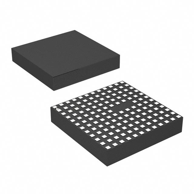
n Small, Low Profile Surface Mount LGA Package
(15mm × 15mm × 2.8mm)
The LTM®4607 is a high efficiency switching mode buckboost power supply. Included in the package are the
switching controller, power FETs, and support components.
Operating over an input voltage range of 4.5V to 36V, the
LTM4607 supports an output voltage range of 0.8V to
24V, set by a resistor. This high efficiency design delivers
up to 5A continuous current in boost mode (10A in buck
mode). Only the inductor, sense resistor, bulk input and
output capacitors are needed to finish the design.
n
The low profile package enables utilization of unused space
on the bottom of PC boards for high density point of load
regulation. The high switching frequency and current
mode architecture enable a very fast transient response
to line and load changes without sacrificing stability. The
LTM4607 can be frequency synchronized with an external
clock to reduce undesirable frequency harmonics.
Applications
Fault protection features include overvoltage and foldback
current protection. The DC/DC µModule® regulator is
offered in a small thermally enhanced 15mm × 15mm ×
2.8mm LGA package. The LTM4607 is Pb-free and RoHS
compliant.
Telecom, Servers and Networking Equipment
n Industrial and Automotive Equipment
n High Power Battery-Operated Devices
n
L, LT, LTC, LTM, Linear Technology, the Linear logo, µModule and PolyPhase are registered
trademarks and No RSENSE is a trademark of Linear Technology Corporation. All other
trademarks are the property of their respective owners.
Typical Application
Efficiency and Power Loss
vs Input Voltage
20V/2.5A Buck-Boost DC/DC µModule Regulator with 4.5V to 36V Input
VIN
PLLIN V
OUT
RUN
LTM4607
4.7µH
+
330µF
25V
VOUT
20V
2.5A
SW1
SW2
RSENSE
SENSE+
0.1µF
SS
SGND
SENSE–
PGND
R2
7mΩ
99
5
98
97
4
96
3
95
94
2
93
92
1
91
VFB
4607 TA01
6
VOUT = 20V, 2.5A
ƒ = 200kHz
POWER LOSS (W)
10µF
35V
FCB
ON/OFF
100
CLOCK SYNC
10µF
50V
EFFICIENCY (%)
VIN
4.5V TO 36V
4.12k
90
6
11
16
21
VIN (V)
26
31
0
36
4607 TA01b
4607fc
For more information www.linear.com/LTM4607
1
�LTM4607
Absolute Maximum Ratings
Pin Configuration
(Note 1)
(See Table 6 Pin Assignment)
VIN.............................................................. –0.3V to 36V
VOUT.............................................................. 0.8V to 25V
INTVCC, EXTVCC, RUN, SS, PGOOD.............. –0.3V to 7V
SW1 (Note 6)................................................. –5V to 25V
SW2 (Note 6)................................................. –5V to 36V
VFB, COMP................................................. –0.3V to 2.4V
FCB, STBYMD........................................–0.3V to INTVCC
PLLIN......................................................... –0.3V to 5.5V
PLLFLTR.................................................... –0.3V to 2.7V
Operating Temperature Range
(Note 2).....................................................–40°C to 85°C
Storage Temperature Range................... –55°C to 125°C
TOP VIEW
BANK 2
M
L
BANK 4
BANK 1
K
J
H
BANK 5
BANK 3
G
F
E
D
BANK 6
C
B
A
1
2
3
4
5
6
7
8
9
10
11
12
LGA PACKAGE
141-LEAD (15mm × 15mm × 2.8mm)
TJMAX = 125°C, θJP = 4°C/W, WEIGHT = 1.5g
order information
PART MARKING*
DEVICE
FINISH CODE
PACKAGE
TYPE
MSL
RATING
Au (RoHS)
LTM4607V
e4
LGA
3
–40°C to 85°C
Au (RoHS)
LTM4607V
e4
LGA
3
–40°C to 85°C
PART NUMBER
PAD OR BALL FINISH
LTM4607EV#PBF
LTM4607IV#PBF
TEMPERATURE RANGE
(NOTE 2)
Consult Marketing for parts specified with wider operating temperature
ranges. *Device temperature grade is indicated by a label on the shipping
container. Pad or ball finish code is per IPC/JEDEC J-STD-609.
• Recommended LGA and BGA PCB Assembly and Manufacturing
Procedures:
www.linear.com/umodule/pcbassembly
• Terminal Finish Part Marking:
www.linear.com/leadfree
• LGA and BGA Package and Tray Drawings:
www.linear.com/packaging
Electrical
Characteristics
The l denotes the specifications which apply over the full operating
temperature range, otherwise specifications are at TA = 25°C (Note 2), VIN = 12V. Per typical application (front page) configuration.
SYMBOL
PARAMETER
CONDITIONS
MIN
TYP
MAX
UNITS
Input Specifications
VIN(DC)
Input DC Voltage
VIN(UVLO)
Undervoltage Lockout Threshold
VIN Falling
IQ(VIN)
Input Supply Bias Current
Normal
Standby
Shutdown Supply Current
VRUN = 0V, VSTBYMD > 2V
VRUN = 0V, VSTBYMD = Open
2
l
l
4.5
3.4
2.8
1.6
35
36
V
4
V
60
mA
mA
µA
4607fc
For more information www.linear.com/LTM4607
�LTM4607
Electrical
Characteristics
The l denotes the specifications which apply over the full operating
temperature range, otherwise specifications are at TA = 25°C (Note 2), VIN = 12V. Per typical application (front page) configuration.
SYMBOL
PARAMETER
CONDITIONS
MIN
TYP
MAX
UNITS
Output Specifications
IOUTDC
Output Continuous Current Range
VIN = 32V, VOUT = 12V
(See Output Current Derating Curves VIN = 6V, VOUT = 12V
for Different VIN, VOUT and TA)
ΔVFB/VFB(NOM)
Reference Voltage Line Regulation
Accuracy
VIN = 4.5V to 36V, VCOMP = 1.2V (Note 3)
ΔVFB/VFB(LOAD)
Load Regulation Accuracy
VCOMP = 1.2V to 0.7V
VCOMP = 1.2V to 1.8V (Note 3)
M1 tr
Turn-On Time (Note 4)
Drain to Source Voltage VDS = 12V, Bias
Current ISW = 10mA
50
ns
M1 tf
Turn-Off Time
Drain to Source Voltage VDS = 12V, Bias
Current ISW = 10mA
40
ns
M3 tr
Turn-On Time
Drain to Source Voltage VDS = 12V, Bias
Current ISW = 10mA
25
ns
M3 tf
Turn-Off Time
Drain to Source Voltage VDS = 12V, Bias
Current ISW = 10mA
20
ns
M2, M4 tr
Turn-On Time
Drain to Source Voltage VDS = 12V, Bias
Current ISW = 10mA
20
ns
M2, M4 tf
Turn-Off Time
Drain to Source Voltage VDS = 12V, Bias
Current ISW = 10mA
20
ns
t1d
M1 Off to M2 On Delay (Note 4)
Drain to Source Voltage VDS = 12V, Bias
Current ISW = 10mA
50
ns
t2d
M2 Off to M1 On Delay
Drain to Source Voltage VDS = 12V, Bias
Current ISW = 10mA
50
ns
t3d
M3 Off to M4 On Delay
Drain to Source Voltage VDS = 12V, Bias
Current ISW = 10mA
50
ns
t4d
M4 Off to M3 On Delay
Drain to Source Voltage VDS = 12V, Bias
Current ISW = 10mA
50
ns
Mode Transition 1
M2 Off to M4 On Delay
Drain to Source Voltage VDS = 12V, Bias
Current ISW = 10mA
220
ns
Mode Transition 2
M4 Off to M2 On Delay
Drain to Source Voltage VDS = 12V, Bias
Current ISW = 10mA
220
ns
M1 RDS(ON)
Static Drain-to-Source
On-Resistance
Bias Current ISW = 3A
10
mΩ
M2 RDS(ON)
Static Drain-to-Source
On-Resistance
Bias Current ISW = 3A
12
18
mΩ
M3 RDS(ON)
Static Drain-to-Source
On-Resistance
Bias Current ISW = 3A
8
12
mΩ
M4 RDS(ON)
Static Drain-to-Source
On-Resistance
Bias Current ISW = 3A
8
12
mΩ
10
5
l
l
A
A
0.002
0.02
%/V
0.15
–0.15
0.5
–0.5
%
%
Switch Section
Oscillator and Phase-Locked Loop
fNOM
Nominal Frequency
VPLLFLTR = 1.2V
260
300
330
kHz
fLOW
Lowest Frequency
VPLLFLTR = 0V
170
200
220
kHz
fHIGH
Highest Frequency
VPLLFLTR = 2.4V
340
400
440
kHz
RPLLIN
PLLIN Input Resistance
IPLLFLTR
Phase Detector Output Current
fPLLIN < fOSC
fPLLIN > fOSC
50
kΩ
–15
15
µA
µA
4607fc
For more information www.linear.com/LTM4607
3
�LTM4607
Electrical
Characteristics
The l denotes the specifications which apply over the full operating
temperature range, otherwise specifications are at TA = 25°C (Note 2), VIN = 12V. Per typical application (front page) configuration.
SYMBOL
PARAMETER
CONDITIONS
MIN
TYP
MAX
UNITS
VFB
Feedback Reference Voltage
VCOMP = 1.2V
0.792
0.8
0.808
V
VRUN
RUN Pin ON/OFF Threshold
1
1.6
2.2
V
ISS
Soft-Start Charging Current
VRUN = 2.2V
VSTBYMD(START)
Start-Up Threshold
VSTBYMD Rising
VSTBYMD(KA)
Keep-Active Power On Threshold
VSTBYMD Rising, VRUN = 0V
VFCB
Forced Continuous Threshold
IFCB
Forced Continuous Pin Current
VFCB = 0.85V
VBURST
Burst Inhibit (Constant Frequency)
Threshold
Measured at FCB Pin
DF(BOOST, MAX)
Maximum Duty Factor
% Switch M4 On
99
%
DF(BUCK, MAX)
Maximum Duty Factor
% Switch M1 On
99
%
tON(MIN, BUCK)
Minimum On-Time for Synchronous Switch M1 (Note 5)
Switch in Buck Operation
RFBHI
Resistor Between VOUT and VFB Pins
Control Section
l
1
1.7
µA
0.4
0.7
V
1.25
V
0.76
0.8
0.84
V
–0.3
–0.2
–0.1
µA
5.3
5.5
V
99.5
200
250
ns
100
100.5
kΩ
6
6.3
V
0.3
2
%
Internal VCC Regulator
INTVCC
Internal VCC Voltage
VIN > 7V, VEXTVCC = 5V
ΔVLDO/VLDO
Internal VCC Load Regulation
ICC = 0mA to 20mA, VEXTVCC = 5V
VEXTVCC
EXTVCC Switchover Voltage
ICC = 20mA, VEXTVCC Rising
ΔVEXTVCC(HYS)
EXTVCC Switchover Hysteresis
ΔVEXTVCC
EXTVCC Switch Drop Voltage
l
l
5.7
5.4
ICC = 20mA, VEXTVCC = 6V
5.6
V
300
mV
60
150
mV
160
–130
190
–150
mV
mV
Current Sensing Section
VSENSE(MAX)
Maximum Current Sense Threshold
Boost Mode
Buck Mode
VSENSE(MIN, BUCK)
Minimum Current Sense Threshold
Discontinuous Mode
–=V
l
l
–95
+
SENSE = 0V
–6
mV
–380
µA
Sense Pins Total Source Current
VSENSE
ΔVFBH
PGOOD Upper Threshold
VFB Rising
5.5
7.5
10
%
ΔVFBL
PGOOD Lower Threshold
VFB Falling
–5.5
–7.5
–10
%
ΔVFB(HYS)
PGOOD Hysteresis
VFB Returning
2.5
VPGL
PGOOD Low Voltage
IPGOOD = 2mA
0.2
IPGOOD
PGOOD Leakage Current
VPGOOD = 5V
ISENSE
PGOOD
Note 1: Stresses beyond those listed under Absolute Maximum Ratings
may cause permanent damage to the device. Exposure to any Absolute
Maximum Rating condition for extended periods may affect device
reliability and lifetime.
Note 2: The LTM4607E is guaranteed to meet specifications from 0°C to
85°C operating temperature range. Specifications over the –40°C to 85°C
operating temperature range are assured by design, characterization and
correlation with statistical process controls. The LTM4607I is guaranteed
over the –40°C to 85°C operating temperature range.
4
%
0.3
V
1
µA
Note 3: The LTM4607 is tested in a feedback loop that servos VCOMP to a
specified voltage and measures the resultant VFB.
Note 4: Turn-on and turn-off time are measured using 10% and 90%
levels. Transition delay time is measured using 50% levels.
Note 5: 100% test at wafer level only.
Note 6: Absolute Maximum Rating of –5V on SW1 and SW2 is under
transient condition only.
4607fc
For more information www.linear.com/LTM4607
�LTM4607
Typical Performance Characteristics
Efficiency vs Load Current
12VIN to 12VOUT
100
100
90
90
90
80
80
80
70
70
70
60
50
40
30
20
0
0.01
0.1
1
LOAD CURRENT (A)
60
50
40
30
0
0.01
0.1
1
LOAD CURRENT (A)
4607 G01
85
80
2
4
6
8
LOAD CURRENT (A)
10
100
99
98
98
97
97
96
95
94
93
90
0
2
94
93
28VIN to 24VOUT
32VIN to 24VOUT
36VIN to 24VOUT
90
0
1
3
2
4
5
LOAD CURRENT (A)
4607 G05
Efficiency vs Load Current
3.3µH Inductor
6
7
4607 G06
Transient Response from
12VIN to 12VOUT
Transient Response from
6VIN to 12VOUT
100
EFFICIENCY (%)
95
91
8
4
6
LOAD CURRENT (A)
96
92
28VIN to 20VOUT
32VIN to 20VOUT
36VIN to 20VOUT
4607 G04
95
100
Efficiency vs Load Current
8µH Inductor
99
91
12
0.1
1
10
LOAD CURRENT (A)
4607 G03
100
92
5VIN TO 5VOUT
12VIN TO 5VOUT
32VIN TO 5VOUT
0
0
0.01
10
EFFICIENCY (%)
EFFICIENCY (%)
EFFICIENCY (%)
95
90
SKIP CYCLE
DCM
CCM
10
Efficiency vs Load Current
6µH Inductor
100
70
50
40
4607 G02
Efficiency vs Load Current
3.3µH Inductor
75
60
20
BURST
DCM
CCM
10
10
Efficiency vs Load Current
32VIN to 12VOUT
30
20
BURST
DCM
CCM
10
EFFICIENCY (%)
100
EFFICIENCY (%)
EFFICIENCY (%)
Efficiency vs Load Current
6VIN to 12VOUT
(Refer to Figure 18)
IOUT
2A/DIV
IOUT
2A/DIV
VOUT
200mV/DIV
VOUT
200mV/DIV
90
85
80
200µs/DIV
70
LOAD STEP: 0A TO 3A AT CCM
OUTPUT CAPS: 4× 22µF CERAMIC CAPS AND
2× 180µF ELECTROLYTIC CAPS
2× 15mΩ SENSING RESISTORS
5VIN to 16VOUT
5VIN to 20VOUT
5VIN to 24VOUT
75
0
0.5
1.5
1
2
LOAD CURRENT (A)
2.5
4607 G08
200µs/DIV
4607 G09
LOAD STEP: 0A TO 3A AT CCM
OUTPUT CAPS: 4× 22µF CERAMIC CAPS AND
2× 180µF ELECTROLYTIC CAPS
2× 15mΩ SENSING RESISTORS
3
4607 G07
4607fc
For more information www.linear.com/LTM4607
5
�LTM4607
Typical Performance Characteristics
Transient Response from
32VIN to 12VOUT
Start-Up with 6VIN to 12VOUT at
IOUT = 5A
IOUT
2A/DIV
VOUT
100mV/DIV
200µs/DIV
IL
5A/DIV
IL
5A/DIV
IIN
5A/DIV
IIN
2A/DIV
VOUT
10V/DIV
VOUT
10V/DIV
4607 G10
50ms/DIV
4607 G11
10ms/DIV
4607 G12
LOAD STEP: 0A TO 5A AT CCM
OUTPUT CAPS: 4× 22µF CERAMIC CAPS AND
2× 180µF ELECTROLYTIC CAPS
2× 12mΩ SENSING RESISTORS
0.1µF SOFT-START CAP
OUTPUT CAPS: 4× 22µF CERAMIC CAPS AND
2× 180µF ELECTROLYTIC CAPS
2× 12mΩ SENSING RESISTORS
0.1µF SOFT-START CAP
OUTPUT CAPS: 4× 22µF CERAMIC CAPS AND
2× 180µF ELECTROLYTIC CAPS
2× 12mΩ SENSING RESISTORS
Short-Circuit with 6VIN to 12VOUT
at IOUT = 5A
Short-Circuit with 32VIN to 12VOUT
at IOUT = 5A
Short-Circuit with 36VIN to 24VOUT
at IOUT = 6A
VOUT
5V/DIV
IIN
10A/DIV
20µs/DIV
4607 G13
OUTPUT CAPS: 4× 22µF CERAMIC CAPS AND
2× 180µF ELECTROLYTIC CAPS
2× 12mΩ SENSING RESISTORS
4605 G11
4605 G11
4605 G11
6
Start-Up with 32VIN to 12VOUT at
IOUT = 5A
IIN
2A/DIV
VOUT
10V/DIV
VOUT
5V/DIV
IIN
2A/DIV
50µs/DIV
4607 G14
OUTPUT CAPS: 4× 22µF CERAMIC CAPS AND
2× 180µF ELECTROLYTIC CAPS
2× 12mΩ SENSING RESISTORS
20µs/DIV
4607 G15
OUTPUT CAPS: 4× 22µF CERAMIC CAPS AND
2× 180µF ELECTROLYTIC CAPS
15mΩ SENSING RESISTORS
4607fc
For more information www.linear.com/LTM4607
�LTM4607
Pin Functions
VIN (Bank 1): Power Input Pins. Apply input voltage between these pins and PGND pins. Recommend placing
input decoupling capacitance directly between VIN pins
and PGND pins.
VOUT (Bank 5): Power Output Pins. Apply output load
between these pins and PGND pins. Recommend placing
output decoupling capacitance directly between these pins
and PGND pins.
PGND (Bank 6): Power Ground Pins for Both Input and
Output Returns.
SW1, SW2 (Bank 4, Bank 2): Switch Nodes. The power
inductor is connected between SW1 and SW2.
RSENSE (Bank 3): Sensing Resistor Pin. The sensing resistor is connected from this pin to PGND.
SENSE+ (Pin A4): Positive Input to the Current Sense and
Reverse Current Detect Comparators.
SENSE– (Pin A5): Negative Input to the Current Sense and
Reverse Current Detect Comparators.
EXTVCC (Pin F6): External VCC Input. When EXTVCC exceeds
5.7V, an internal switch connects this pin to INTVCC and
shuts down the internal regulator so that the controller and
gate drive power is drawn from EXTVCC. Do not exceed
7V at this pin and ensure that EXTVCC < VIN.
INTVCC (Pin F5): Internal 6V Regulator Output. This pin
is for additional decoupling of the 6V internal regulator.
PLLIN (Pin B9): External Clock Synchronization Input
to the Phase Detector. This pin is internally terminated
to SGND with a 50k resistor. The phase-locked loop will
force the rising bottom gate signal of the controller to be
synchronized with the rising edge of PLLIN signal.
PLLFLTR (Pin B8): The lowpass filter of the phase-locked
loop is tied to this pin. This pin can also be used to set the
frequency of the internal oscillator with an AC or DC voltage. See the Applications Information section for details.
STBYMD (Pin A10): LDO Control Pin. Determines whether
the internal LDO remains active when the controller is
shut down. See the Operations section for details. If the
STBYMD pin is pulled to ground, the SS pin is internally
pulled to ground to disable start-up and thereby providing a single control pin for turning off the controller. An
internal decoupling capacitor is tied to this pin.
VFB (Pin B6): The Negative Input of the Error Amplifier.
Internally, this pin is connected to VOUT with a 100k precision resistor. Different output voltages can be programmed
with an additional resistor between VFB and SGND pins.
See the Applications Information section.
FCB (Pin A9): Forced Continuous Control Input. The
voltage applied to this pin sets the operating mode of the
module. When the applied voltage is less than 0.8V, the
forced continuous current mode is active. When this pin
is allowed to float, the Burst Mode operation is active in
boost operation and the skip cycle mode is active in buck
operation. When the pin is tied to INTVCC, the constant
frequency discontinuous current mode is active in buck or
boost operation. See the Applications Information section.
SGND (Pin A7): Signal Ground Pin. This pin connects to
PGND at output capacitor point.
COMP (Pin B7): Current Control Threshold and Error
Amplifier Compensation Point. The current comparator
threshold increases with this control voltage. The voltage
ranges from 0V to 2.4V.
PGOOD (Pin B5): Output Voltage Power Good Indicator.
Open drain logic output that is pulled to ground when the
output voltage is not within ±10% of the regulation point,
after a 25µs power bad mask timer expires.
RUN (Pin A8): Run Control Pin. A voltage below 1.6V will
turn off the module. There is a 100k resistor between the
RUN pin and SGND in the module. Do not apply more than
6V to this pin. See the Applications Information section.
SS (Pin A6): Soft-Start Pin. Soft-start reduces the input
surge current from the power source by gradually increasing the controller’s current limit.
4607fc
For more information www.linear.com/LTM4607
7
�LTM4607
Simplified Block Diagram
VIN
4.5V TO 36V
EXTVCC
C1
CIN
M1
SW2
INTVCC
M2
PGOOD
L
SW1
RUN
ON/OFF
VOUT
100k
STBYMD
12V
5A
CO1
M3
COUT
0.1µF
100k
COMP
VFB
M4
CONTROLLER
INT
COMP
RFB
7.15k
RSENSE
SENSE+
SS
SS
0.1µF
PLLIN
INT
FILTER
PLLFLTR
RSENSE
SENSE–
PGND
INT
FILTER
FCB
1000pF
SGND
TO PGND PLANE AS
SHOWN IN FIGURE 15
4607 BD
Figure 1. Simplified LTM4607 Block Diagram
Decoupling
Requirements TA = 25°C. Use Figure 1 configuration.
SYMBOL
PARAMETER
CONDITIONS
CIN
External Input Capacitor Requirement
(VIN = 4.5V to 36V, VOUT = 12V)
IOUT = 5A
10
COUT
External Output Capacitor Requirement
(VIN = 4.5V to 36V, VOUT = 12V)
IOUT = 5A
200
8
MIN
TYP
MAX
UNITS
µF
300
µF
4607fc
For more information www.linear.com/LTM4607
�LTM4607
Operation
Power Module Description
The LTM4607 is a non-isolated buck-boost DC/DC power
supply. It can deliver a wide range output voltage from 0.8V
to 24V over a wide input range from 4.5V to 36V, by only
adding the sensing resistor, inductor and some external
input and output capacitors. It provides precisely regulated
output voltage programmable via one external resistor.
The typical application schematic is shown in Figure 18.
The LTM4607 has an integrated current mode buck-boost
controller, ultralow RDS(ON) FETs with fast switching speed
and integrated Schottky diodes. With current mode control
and internal feedback loop compensation, the LTM4607
module has sufficient stability margins and good transient
performance under a wide range of operating conditions
and with a wide range of output capacitors. The operating
frequency of the LTM4607 can be adjusted from 200kHz
to 400kHz by setting the voltage on the PLLFLTR pin.
Alternatively, its frequency can be synchronized by an input clock signal from the PLLIN pin. The typical switching
frequency is 400kHz.
The Burst Mode and skip-cycle mode operations can be
enabled at light loads to improve efficiency, while the forced
continuous mode and discontinuous mode operations are
used for constant frequency applications. Foldback current
limiting is activated in an overcurrent condition as VFB
drops. Internal overvoltage and undervoltage comparators pull the open-drain PGOOD output low if the output
feedback voltage exits the ±10% window around the
regulation point. Pulling the RUN pin below 1.6V forces
the controller into its shutdown state.
If an external bias supply is applied on the EXTVCC pin,
then an efficiency improvement will occur due to the reduced power loss in the internal linear regulator. This is
especially true at the higher end of the input voltage range.
Applications Information
The typical LTM4607 application circuit is shown in
Figure 18. External component selection is primarily
determined by the maximum load current and output
voltage. Refer to Table 3 for specific external capacitor
requirements for a particular application.
Output Voltage Programming
The PWM controller has an internal 0.8V reference voltage.
As shown in the Block Diagram, a 100k internal feedback
resistor connects VOUT and VFB pins together. Adding a
resistor RFB from the VFB pin to the SGND pin programs
the output voltage:
VOUT = 0.8V •
100k +RFB
RFB
Operation Frequency Selection
The LTM4607 uses current mode control architecture at
constant switching frequency, which is determined by the
internal oscillator’s capacitor. This internal capacitor is
charged by a fixed current plus an additional current that
is proportional to the voltage applied to the PLLFLTR pin.
The PLLFLTR pin can be grounded to lower the frequency
to 200kHz or tied to 2.4V to yield approximately 400kHz.
When PLLFLTR is left open, the PLLFLTR pin goes low,
forcing the oscillator to its minimum frequency.
A graph for the voltage applied to the PLLFLTR pin vs
frequency is given in Figure 2. As the operating frequency
increases, the gate charge losses will be higher, thus the
efficiency is lower. The maximum switching frequency is
approximately 400kHz.
Table 1. RFB Resistor (0.5%) vs Output Voltage
VOUT
0.8V
1.5V
2.5V
3.3V
5V
6V
8V
RFB
Open
115k
47.5k
32.4k
19.1k
15.4k
11k
VOUT
9V
10V
12V
15V
16V
20V
24V
RFB
9.76k
8.66k
7.15k
5.62k
5.23k
4.12k
3.4k
Frequency Synchronization
The LTM4607 can also be synchronized to an external
source via the PLLIN pin instead of adjusting the voltage on
the PLLFLTR pin directly. The power module has a phaselocked loop comprised of an internal voltage controlled
4607fc
For more information www.linear.com/LTM4607
9
�LTM4607
Applications Information
oscillator and a phase detector. This allows turning on the
internal top MOSFET for locking to the rising edge of the
external clock. A pulse detection circuit is used to detect a
clock on the PLLIN pin to turn on the phase-locked loop.
The input pulse width of the clock has to be at least 400ns,
and 2V in amplitude. The synchronized frequency ranges
from 200kHz to 400kHz, corresponding to a DC voltage
input from 0V to 2.4V at PLLFLTR. During the start up of
the regulator, the phase-locked loop function is disabled.
450
OPERATING FREQUENCY (kHz)
400
350
300
250
200
150
100
50
0
0
1.0
1.5
2.0
0.5
PLLFLTR PIN VOLTAGE (V)
2.5
4607 F02
Figure 2. Frequency vs PLLFLTR Pin Voltage
Low Current Operation
To improve efficiency at low output current operation,
LTM4607 provides three modes for both buck and boost
operations by accepting a logic input on the FCB pin. Table
2 shows the different operation modes.
The MOSFETs will turn on for several cycles, followed by a
variable “sleep” interval depending upon the load current.
During buck operation, skip-cycle mode sets a minimum
positive inductor current level. In this mode, some cycles
will be skipped when the output load current drops below
1% of the maximum designed load in order to maintain
the output voltage.
When the FCB pin voltage is tied to the INTVCC pin, the
controller enters constant frequency discontinuous current
mode (DCM). For boost operation, if the output voltage is
high enough, the controller can enter the continuous current
buck mode for one cycle to discharge inductor current.
In the following cycle, the controller will resume DCM
boost operation. For buck operation, constant frequency
discontinuous current mode is turned on if the preset
minimum negative inductor current level is reached. At
very light loads, this constant frequency operation is not
as efficient as Burst Mode operation or skip-cycle, but
does provide low noise, constant frequency operation.
Input Capacitors
In boost mode, since the input current is continuous, only
minimum input capacitors are required. However, the input
current is discontinuous in buck mode. So the selection
of input capacitor CIN is driven by the need of filtering the
input square wave current.
For a buck converter, the switching duty-cycle can be
estimated as:
D=
Table 2. Different Operating Modes
FCB PIN
BUCK
BOOST
0V to 0.75V
Force Continuous Mode
Force Continuous Mode
0.85V to 5V
Skip-Cycle Mode
Burst Mode Operation
>5.3V
DCM with Constant Freq
DCM with Constant Freq
When the FCB pin voltage is lower than 0.8V, the controller
behaves as a continuous, PWM current mode synchronous
switching regulator. When the FCB pin voltage is below
VINTVCC – 1V, but greater than 0.85V, the controller enters
Burst Mode operation in boost operation or enters skipcycle mode in buck operation. During boost operation,
Burst Mode operation is activated if the load current is
lower than the preset minimum output current level.
10
VOUT
VIN
Without considering the inductor current ripple, the RMS
current of the input capacitor can be estimated as:
ICIN(RMS) =
IOUT(MAX)
η
• D • (1−D)
In the above equation, η is the estimated efficiency of the
power module. CIN can be a switcher-rated electrolytic
aluminum capacitor, OS-CON capacitor or high volume ceramic capacitors. Note the capacitor ripple current ratings
are often based on temperature and hours of life. This
makes it advisable to properly derate the input capacitor,
4607fc
For more information www.linear.com/LTM4607
�LTM4607
Applications Information
or choose a capacitor rated at a higher temperature than
required. Always contact the capacitor manufacturer for
derating requirements.
L BOOST ≥
Output Capacitors
In boost mode, the discontinuous current shifts from the
input to the output, so the output capacitor COUT must be
capable of reducing the output voltage ripple.
For boost and buck modes, the steady ripple due to charging and discharging the bulk capacitance is given by:
VRIPPLE,BOOST =
VRIPPLE,BUCK =
IOUT(MAX) • ( VOUT − VIN(MIN) )
COUT • VOUT • ƒ
VOUT • ( VIN(MAX) − VOUT )
8 • L • COUT • VIN(MAX) • ƒ2
The steady ripple due to the voltage drop across the ESR
(effective series resistance) is given by:
inductor current. In the inductor design, the worst cases
in continuous mode are considered as follows:
VESR,BUCK = ΔIL(MAX) • ESR
VESR,BOOST = IL(MAX) • ESR
The LTM4607 is designed for low output voltage ripple.
The bulk output capacitors defined as COUT are chosen
with low enough ESR to meet the output voltage ripple and
transient requirements. COUT can be the low ESR tantalum
capacitor, the low ESR polymer capacitor or the ceramic
capacitor. Multiple capacitors can be placed in parallel to
meet the ESR and RMS current handling requirements.
The typical capacitance is 300µF. Additional output filtering
may be required by the system designer, if further reduction of output ripple or dynamic transient spike is required.
Table 3 shows a matrix of different output voltages and
output capacitors to minimize the voltage droop and
overshoot at a current transient.
Inductor Selection
The inductor is chiefly decided by the required ripple current and the operating frequency. The inductor current
ripple ΔIL is typically set to 20% to 40% of the maximum
L BUCK ≥
(
VIN • VOUT(MAX) − VIN
)
VOUT(MAX) • ƒ •IOUT(MAX) • Ripple%
VOUT • ( VIN(MAX) − VOUT )
VIN(MAX) • ƒ •IOUT(MAX) • Ripple%
where:
ƒ is operating frequency, Hz
Ripple% is allowable inductor current ripple, %
VOUT(MAX) is maximum output voltage, V
VIN(MAX) is maximum input voltage, V
VOUT is output voltage, V
IOUT(MAX) is maximum output load current, A
The inductor should have low DC resistance to reduce the
I2R losses, and must be able to handle the peak inductor
current without saturation. To minimize radiated noise,
use a toroid, pot core or shielded bobbin inductor. Please
refer to Table 3 for the recommended inductors for different cases.
RSENSE Selection and Maximum Output Current
RSENSE is chosen based on the required inductor current.
Since the maximum inductor valley current at buck mode
is much lower than the inductor peak current at boost
mode, different sensing resistors are suggested for use
in buck and boost modes.
The current comparator threshold sets the peak of the
inductor current in boost mode and the maximum inductor
valley current in buck mode. In boost mode, the allowed
maximum average load current is:
⎛ 160mV ΔI ⎞ V
IOUT(MAX,BOOST) = ⎜
− L ⎟ • IN
2 ⎠ VOUT
⎝ RSENSE
where ΔIL is peak-to-peak inductor ripple current.
4607fc
For more information www.linear.com/LTM4607
11
�LTM4607
Applications Information
In buck mode, the allowed maximum average load current is:
IOUT(MAX,BUCK) =
130mV ΔIL
+
RSENSE 2
The maximum current sensing RSENSE value for the boost
mode is:
RSENSE(MAX,BOOST) =
2 • 130mV
2 •IOUT(MAX,BUCK) – ΔIL
A 20% to 30% margin on the calculated sensing resistor
is usually recommended. Please refer to Table 3 for the
recommended sensing resistors for different applications.
Soft-Start
The SS pin provides a means to soft-start the regulator.
A capacitor on this pin will program the ramp rate of the
output voltage. A 1.7µA current source will charge up the
external soft-start capacitor. This will control the ramp
of the internal reference and the output voltage. The total
soft-start time can be calculated as:
tSOFTSTART =
2.4V • CSS
1.7µA
When the RUN pin falls below 1.6V, then soft-start pin
is reset to allow for proper soft-start control when the
regulator is enabled again. Current foldback and force
continuous mode are disabled during the soft-start process. The soft-start function can also be used to control
the output ramp up time, so that another regulator can be
easily tracked. Do not apply more than 6V to the SS pin.
12
The RUN pin can also be used as an undervoltage lockout
(UVLO) function by connecting a resistor from the input
supply to the RUN pin. The equation:
V _UVLO =
R1+R2
• 1.6V
R2
Power Good
The maximum current sensing RSENSE value for the buck
mode is:
The RUN pin is used to enable the power module. The pin
can be driven with a logic input, not to exceed 6V.
2 • 160mV • VIN
2 •IOUT(MAX,BOOST) • VOUT + ΔIL • VIN
RSENSE(MAX,BUCK) =
Run Enable
The PGOOD pin is an open drain pin that can be used to
monitor valid output voltage regulation. This pin monitors
a ±7.5% window around the regulation point.
COMP Pin
This pin is the external compensation pin. The module
has already been internally compensated for most output
voltages. A spice model is available for other control loop
optimization.
Fault Conditions: Current Limit and Overcurrent
Foldback
LTM4607 has a current mode controller, which inherently
limits the cycle-by-cycle inductor current not only in steady
state operation, but also in transient. Refer to Table 3.
To further limit current in the event of an overload condition, the LTM4607 provides foldback current limiting. If the
output voltage falls by more than 70%, then the maximum
output current is progressively lowered to about 30% of
its full current limit value for boost mode and about 40%
for buck mode.
Standby Mode (STBYMD)
The standby mode (STBYMD) pin provides several choices
for start-up and standby operational modes. If the pin is
pulled to ground, the SS pin is internally pulled to ground,
preventing start-up and thereby providing a single control
4607fc
For more information www.linear.com/LTM4607
�LTM4607
Applications Information
pin for turning off the controller. If the pin is left open
or decoupled with a capacitor to ground, the SS pin is
internally provided with a starting current, permitting
external control for turning on the controller. If the pin
is connected to a voltage greater than 1.25V, the internal
regulator (INTVCC) will be on even when the controller is
shut down (RUN pin voltage