LTM8023
2A, 36V DC/DC
Step-Down µModule
Regulator
DESCRIPTION
FEATURES
Complete Step-Down Switch Mode Power Supply
Wide Input Voltage Range: 3.6V to 36V
2A Output Current
0.8V to 10V Output Voltage
Selectable Switching Frequency: 200kHz to 2.4MHz
Current Mode Control
Programmable Soft-Start
SnPb (BGA) or RoHS Compliant (LGA and BGA)
Finish
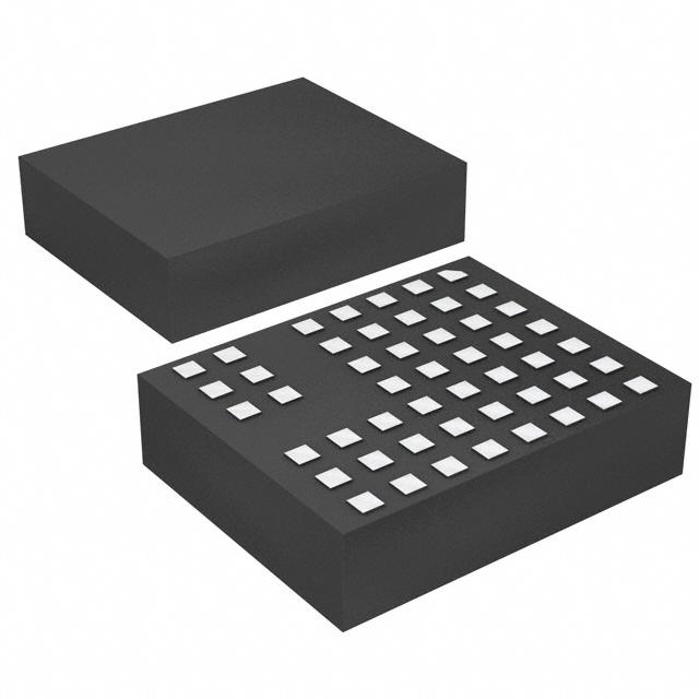
n Tiny, Low Profile, Surface Mount LGA (9mm ×
11.25mm × 2.82mm) and BGA (9mm × 11.25mm ×
3.42mm) Packages
n
n
n
n
n
n
n
n
APPLICATIONS
n
n
n
n
n
Automotive Battery Regulation
Power for Portable Products
Distributed Supply Regulation
Industrial Supplies
Wall Transformer Regulation
The LTM®8023 is a complete 2A, DC/DC step-down power
supply. Included in the package are the switching controller,
power switches, inductor, and all support components.
Operating over an input voltage range of 3.6V to 36V, the
LTM8023 supports an output voltage range of 0.8V to 10V,
and a switching frequency range of 200kHz to 2.4MHz,
each set by a single resistor. Only the bulk input and output
filter capacitors are needed to finish the design.
The low profile package enables utilization of unused
space on the bottom of PC boards for high density point
of load regulation.
The LTM8023 is packaged in a thermally enhanced, compact and low profile over-molded land grid array (LGA)
and ball grid array (BGA) packages suitable for automated
assembly by standard surface mount equipment. The
LTM8023 is available with SnPb (BGA) or RoHS compliant terminal finish.
L, LT, LTC, LTM, Linear Technology, the Linear logo, Burst Mode and µModule are registered
trademarks of Linear Technology Corporation. All other trademarks are the property of their
respective owners.
TYPICAL APPLICATION
5.5VIN to 36VIN, 3.3V/2A DC/DC µModule® Converter
VIN*
5.5V TO 36V
VIN
VOUT
AUX
22µF
BIAS
SHARE
LTM8023
PGOOD
RT
1.6
1.4
80
1.2
75
1.0
70
0.8
65
0.6
0.4
VIN = 12V
VOUT = 3.3V
f = 650 kHz
55
GND SYNC
8023 TA01
49.9k
85
60
ADJ
SELECTABLE
OPERATING
FREQUENCY
1.8
154k
50
*RUNNING VOLTAGE RANGE. PLEASE
REFER TO APPLICATIONS INFORMATION
FOR START-UP DETAILS
POWER LOSS (W)
RUN/SS
VOUT
3.3V
2A
EFFICIENCY (%)
2.2µF
Efficiency and Power Loss
90
0.01
0.1
1
LOAD CURRENT (A)
0.2
0
10
8023 TA01b
8023fj
For more information www.linear.com/LTM8023
1
�LTM8023
ABSOLUTE MAXIMUM RATINGS
(Note 1)
VIN + BIAS..................................................................56V
Internal Operating Temperature
(Note 2)................................................... –40°C to 125°C
Storage Temperature.............................. –55°C to 125°C
Solder Temperature................................................ 250°C
VIN, RUN/SS Voltage..................................................40V
ADJ, RT, SHARE Voltage..............................................5V
VOUT, AUX..................................................................10V
PGOOD, SYNC...........................................................30V
BIAS...........................................................................16V
PIN CONFIGURATION
GND (BANK 3)
SHARE RT
ADJ
SHARE RT
GND (BANK 3)
7
ADJ
7
6
SYNC
PGOOD
6
SYNC
PGOOD
5
RUN/SS
5
RUN/SS
BIAS
4
3
VOUT
(BANK 2) 2
VIN
(BANK 1)
BIAS
4
AUX
AUX
3
VOUT
(BANK 2) 2
1
VIN
(BANK 1)
1
A
B
C
D
E
F
G
H
A
LGA PACKAGE
50-LEAD (11.25mm × 9mm × 2.82mm)
B
C
E
D
F
G
H
BGA PACKAGE
50-LEAD (11.25mm × 9mm × 3.42mm)
TJMAX = 125°C, θJA = 30.4°C/W, θJCbottom = 12.2°C/W,
θJCtop = 23.9°C/W, θJB = 12.1°C/W, WEIGHT = 0.9g
θ VALUES DETERMINED PER JEDEC 51-9, 51-12
TJMAX = 125°C, θJA = 32.1°C/W, θJCbottom = 14.8°C/W,
θJCtop = 23.7°C/W, θJB = 14.6°C/W, WEIGHT = 0.9g
θ VALUES DETERMINED PER JEDEC 51-9, 51-12
ORDER INFORMATION
PART NUMBER
PAD OR BALL FINISH
LTM8023EV#PBF
Au (RoHS)
PART MARKING*
DEVICE
FINISH CODE
PACKAGE
TYPE
LTM8023V
e4
LGA
MSL
RATING
3
TEMPERATURE RANGE
(Note 2)
–40°C to 85°C
LTM8023IV#PBF
Au (RoHS)
LTM8023V
e4
LGA
3
–40°C to 85°C
LTM8023MPV#PBF
Au (RoHS)
LTM8023MPV
e4
LGA
3
–55°C to 125°C
LTM8023EY#PBF
SAC305 (RoHS)
LTM8023Y
e1
BGA
3
–40°C to 85°C
LTM8023IY#PBF
SAC305 (RoHS)
LTM8023Y
e1
BGA
3
–40°C to 85°C
LTM8023IY
SnPb (63/37)
LTM8023Y
e0
BGA
3
–40°C to 85°C
LTM8023MPY#PBF
SAC305 (RoHS)
LTM8023Y
e1
BGA
3
–55°C to 125°C
LTM8023MPY
SnPb (63/37)
LTM8023Y
e0
BGA
3
–55°C to 125°C
Consult Marketing for parts specified with wider operating temperature
ranges. *Device temperature grade is indicated by a label on the shipping
container. Pad or ball finish code is per IPC/JEDEC J-STD-609.
• Recommended LGA and BGA PCB Assembly and Manufacturing
Procedures:
www.linear.com/umodule/pcbassembly
• Terminal Finish Part Marking:
www.linear.com/leadfree
• LGA and BGA Package and Tray Drawings:
www.linear.com/packaging
2
8023fj
For more information www.linear.com/LTM8023
�LTM8023
ELECTRICAL
CHARACTERISTICS
The l denotes the specifications which apply over the full operating
temperature range, otherwise specifications are at TA = 25°C. VIN = 10V, VRUN/SS = 10V, VBIAS = 3V, RT = 60.4k, COUT = 4.7µF unless
otherwise specified.
SYMBOL
PARAMETER
VIN
Input DC Voltage
VOUT
Output DC Voltage
RADJ(MIN)
Minimum Allowable RADJ
(Note 4)
IOUT
Continuous Output DC Current
4 ≤ VIN ≤ 36, COUT = 51µF
IQVIN
VIN Quiescent Current
VRUN/SS = 0.2V, RT = 174k
VBIAS = 3V, Not Switching, RT = 174k (E, I)
VBIAS = 3V, Not Switching, RT = 174k (MP)
VBIAS = 0V, Not Switching, RT = 174k
l
l
VRUN/SS = 0.2V, RT = 174k
VBIAS = 3V, Not Switching, RT = 174k (E, I)
VBIAS = 3V, Not Switching, RT = 174k (MP)
VBIAS = 0V, Not Switching, RT = 174k
l
l
IQBIAS
BIAS Quiescent Current
CONDITIONS
MIN
l
TYP
3.6
0A < IOUT ≤ 2A, RADJ Open, COUT = 51µF (Note 3)
0A < IOUT ≤ 2A, RADJ = 43.2k, COUT = 51µF (Note 3)
MAX
36
0.8
10
UNITS
V
V
V
42.2
kΩ
0
2
A
0.1
25
25
85
0.5
60
350
120
µA
µA
µA
µA
0.03
50
50
1
0.5
120
200
5
µA
µA
µA
µA
ΔVOUT/VOUT
Line Regulation
5 ≤ VIN ≤ 36, IOUT = 1A, VOUT = 3.3V, COUT = 51µF
0.1
ΔVOUT/VOUT
Load Regulation
VIN = 24V, 0 ≤ IOUT ≤ 2A, VOUT = 3.3V, COUT = 51µF
0.4
%
VIN = 24V, IOUT = 2A, VOUT = 3.3V, COUT = 51µF
10
mV
325
kHz
VOUT(AC_RMS) Output Ripple (RMS)
fSW
Switching Frequency
RT = 113k, COUT = 51µF
ISC(OUT)
Output Short Circuit Current
VIN = 36V, VOUT = 0V (Note 5)
VADJ
Voltage at ADJ Pin
COUT = 51µF
VBIAS(MIN)
Minimum BIAS Voltage for Proper
Operation
IADJ
Current Out of ADJ Pin
ADJ = 1V, COUT = 51µF
IRUN/SS
RUN/SS Pin Current
VRUN/SS = 2.5V
VIH(RUN/SS)
RUN/SS Input High Voltage
COUT = 51µF
2.9
l
765
A
790
805
mV
2.3
2.8
V
2
5
µA
10
2.5
VIL(RUN/SS)
RUN/SS Input Low Voltage
COUT = 51µF
PGOOD Threshold
VOUT Rising
730
0.2
IPGOOD(O)
PGOOD Leakage
VPGOOD = 30V
0.1
IPGOOD(SINK)
PGOOD Sink Current
VPGOOD = 0.4V
VSYNCIL
SYNC Input Low Threshold
fSYNC = 550kHz, COUT = 51µF
VSYNCIH
SYNC Input High Threshold
fSYNC = 550kHz, COUT = 51µF
ISYNCBIAS
SYNC Pin Bias Current
VSYNC = 0V
200
µA
V
VPGOOD(TH)
Note 1: Stresses beyond those listed under Absolute Maximum Ratings
may cause permanent damage to the device. Exposure to any Absolute
Maximum Rating condition for extended periods may affect device
reliability and lifetime.
Note 2: The LTM8023E is guaranteed to meet performance specifications
from 0°C to 85°C ambient. Specifications over the full –40°C to
85°C ambient operating temperature range are assured by design,
characterization and correlation with statistical process controls. The
LTM8023I is guaranteed to meet specifications over the full –40°C to 85°C
ambient operating temperature range. The LTM8023MP is guaranteed to
%
1
800
µA
µA
0.5
0.7
V
mV
V
V
0.1
µA
meet specifications over the full –55°C to 125°C temperature range. Note
that the maximum internal temperature is determined by specific operating
conditions in conjunction with board layout, the rated package thermal
resistance and other environmental factors.
Note 3: COUT = 51µF is composed of a 4.7µF ceramic capacitor in parallel
with a 47µF electrolytic.
Note 4: Guaranteed by design.
Note 5: Short circuit current at VIN = 36V is guaranteed by characterization
and correlation. 100% tested at VIN = 10V
8023fj
For more information www.linear.com/LTM8023
3
�LTM8023
TYPICAL PERFORMANCE CHARACTERISTICS
Efficiency (8VOUT)
90
VOUT = 8V
90
70
60
50
40
30
20
0.01
0.1
OUTPUT CURRENT (A)
75
70
65
50
0.01
20
0.1
OUTPUT CURRENT (A)
8023 G01
Minimum Required Input Voltage
vs Output Voltage
75
70
65
60
12VIN
24VIN
36VIN
55
1
VOUT = 3.3V
80
60
12VIN
24VIN
36VIN
Efficiency (3.3VOUT)
85
80
EFFICIENCY (%)
EFFICIENCY (%)
90
VOUT = 5V
85
80
5VIN
12VIN
24VIN
36VIN
55
50
0.01
1
0.1
OUTPUT CURRENT (A)
8023 G02
36VIN Start-Up Waveforms
(5VOUT)
1
8023 G03
36VIN Start-Up Waveforms
(3.3VOUT)
IOUT = 2A
18
16
INPUT VOLTAGE (V)
Efficiency (5VOUT)
EFFICIENCY (%)
100
TA = 25°C unless otherwise noted
14
OPERATING FREQUENCY
AS RECOMMENDED
IN TABLE 1
12
10
VOUT
2V/DIV
IIN
0.2A/DIV
VOUT
2V/DIV
IIN
0.2A/DIV
RUN/SS
5V/DIV
RUN/SS
5V/DIV
VIN = 36V
IOUT = 2A
VBIAS = 3V
8
6
50µs/DIV
8023 G05
VIN = 36V
IOUT = 2A
VBIAS = 3V
50µs/DIV
8023 G06
4
2
0
2
4
6
OUTPUT VOLTAGE (V)
8
10
8023 G04
Input Current vs Output Current
1600
VOUT = 8V
1400
800
600
400
12VIN
24VIN
36VIN
200
4
VOUT = 5V
0
500
1000
1500
OUTPUT CURRENT (mA)
2000
8023 G07
VOUT = 3.3V
1800
1600
INPUT CURRENT (mA)
1000
0
Input Current vs Output Current
2000
1000
1200
INPUT CURRENT (mA)
INPUT CURRENT (mA)
Input Current vs Output Current
1200
800
12VIN
24VIN
36VIN
600
400
1400
1200
5VIN
12VIN
24VIN
36VIN
1000
800
600
400
200
200
0
0
500
1000
1500
OUTPUT CURRENT (mA)
2000
8023 G08
0
0
500
1000
1500
OUTPUT CURRENT (mA)
2000
8023 G09
8023fj
For more information www.linear.com/LTM8023
�LTM8023
TYPICAL PERFORMANCE CHARACTERISTICS
Output Short-Circuit Current
vs Input Voltage
BIAS Current vs Load Current
30
3200
2500
25
2600
2400
2200
2000
20
3.3VOUT
5VOUT
8VOUT
15
10
1500
1000
500
5
1800
0
10
20
30
INPUT VOLTAGE (V)
2500
0
40
0
500
1000
1500
LOAD CURRENT (mA)
Load Current
vs Input Voltage (5VOUT, LGA)
1500
1000
0
10
20
30
INPUT VOLTAGE (V)
40
8023 G13
1500
1000
0
40
25°C
40°C
85°C
0
10
8023 G14
20
30
INPUT VOLTAGE (V)
80
60
70
TEMPERATURE RISE (°C)
35
30
25
20
15
10
12VIN
24VIN
36VIN
5
1000
1500
CURRENT (mA)
2000
2500
8023 G16
TEMPERATURE RISE (°C)
50
40
40
30
20
12VIN
24VIN
36VIN
10
0
40
8023 G15
8VOUT Junction Temperature
vs Load (LGA)
45
TEMPERATURE RISE (°C)
20
30
INPUT VOLTAGE (V)
Load Current
vs Input Voltage (3.3VOUT, LGA)
5VOUT Junction Temperature
vs Load (LGA)
50
500
10
500
25°C
40°C
85°C
3.3VOUT Junction Temperature
vs Load (LGA)
0
0
2000
500
0
25°C
40°C
85°C
8023 G11
2500
LOAD CURRENT (mA)
LOAD CURRENT (mA)
0
2000
8023 G10
2000
0
Maximum Load Current
vs Input Voltage (8VOUT, LGA)
2000
LOAD CURRENT (mA)
2800
BIAS CURRENT (mA)
OUTPUT CURRENT (mA)
3000
1600
TA = 25°C unless otherwise noted
0
500
1000
1500
CURRENT (mA)
2000
2500
8023 G17
60
50
40
30
20
16VIN
24VIN
36VIN
10
0
0
500
1000
1500
CURRENT (mA)
2000
2500
8023 G18
8023fj
For more information www.linear.com/LTM8023
5
�LTM8023
TYPICAL PERFORMANCE CHARACTERISTICS
5VOUT Temperature Rise vs
Load Current (BGA)
60
50
50
40
30
20
12VIN
24VIN
36VIN
0
0
6
500
1000
1500
2000
LOAD CURRENT (mA)
2500
8023 G19
8VOUT Temperature Rise vs
Load Current (BGA)
90
80
TEMPERATURE RISE (°C)
60
TEMPERATURE RISE (°C)
TEMPERATURE RISE (°C)
3.3VOUT Temperature Rise vs
Load Current (BGA)
10
TA = 25°C unless otherwise noted
40
30
20
12VIN
24VIN
36VIN
10
0
0
500
1000
1500
2000
LOAD CURRENT (mA)
2500
8023 G20
70
60
50
40
30
20
18VIN
24VIN
36VIN
10
0
0
500
1000
1500
2000
LOAD CURRENT (mA)
2500
8023 G21
8023fj
For more information www.linear.com/LTM8023
�LTM8023
PIN FUNCTIONS
VIN (Bank 1): The VIN pin supplies current to the LTM8023’s
internal regulator and to the internal power switch. This
pin must be locally bypassed with an external, low ESR
capacitor of at least 2.2µF.
VOUT (Bank 2): Power Output Pins. Apply the output filter
capacitor and the output load between these pins and
GND pins.
AUX (Pin F5): Low Current Voltage Source for BIAS. The
VAUX pin is internally connected to VOUT and is placed
adjacent to the BIAS pin to ease printed circuit board
routing. Although this pin is internally connected to VOUT,
do NOT connect this pin to the load. If this pin is not tied
to BIAS, leave it floating.
large impact on the thermal performance of the part. See
the PCB Layout and Thermal Consideration sections for
more details. Return the feedback divider (RADJ) to this net.
RT (Pin G7): The RT pin is used to program the switching
frequency of the LTM8023 by connecting a resistor from
this pin to ground. The Applications Information section of
the data sheet includes a table to determine the resistance
value based on the desired switching frequency. Minimize
capacitance at this pin.
SHARE (Pin F7): Tie this to the SHARE pin of another
LTM8023 when paralleling the outputs. Otherwise, do not
connect (leave floating).
BIAS (Pin G5): The BIAS pin connects to the internal power
bus. Connect to a power source greater than 2.8V. If the
output is greater than 2.8V, connect this pin there. If the
output voltage is less, connect this to a voltage source
between 2.8V and 16V. Also, make sure that BIAS + VIN
is less than 56V.
SYNC (Pin G6): This is the external clock synchronization
input. Ground this pin for low ripple Burst Mode® operation
at low output loads. Tie to a stable voltage source greater
than 0.7V to disable Burst Mode operation. Do not leave
this pin floating. Tie to a clock source for synchronization.
Clock edges should have rise and fall times faster than 1µs.
See synchronizing section in Applications Information.
RUN/SS (Pin H5): Tie RUN/SS pin to ground to shut down
the LTM8023. Tie to 2.5V or more for normal operation.
If the shutdown feature is not used, tie this pin to the VIN
pin. RUN/SS also provides a soft-start function; see the
Applications Information section.
PGOOD (Pin H6): The PGOOD pin is the open-collector
output of an internal comparator. PG remains low until
the ADJ pin is within 10% of the final regulation voltage.
PG output is valid when VIN is above 3.6V and RUN/SS is
high. If this function is not used, leave this pin floating.
GND (Bank 3): Tie these GND pins to a local ground plane
below the LTM8023 and the circuit components. In most
applications, the bulk of the heat flow out of the LTM8023
is through these pads, so the printed circuit design has a
ADJ (Pin H7): The LTM8023 regulates its ADJ pin to 0.79V.
Connect the adjust resistor from this pin to ground. The
value of RADJ is given by the equation RADJ = 394.21/
(VOUT – 0.79), where RADJ is in kΩ.
8023fj
For more information www.linear.com/LTM8023
7
�LTM8023
BLOCK DIAGRAM
VIN
VOUT
4.7µH
0.1µF
4.7pF
499k
10µF
AUX
BIAS
SHARE
RUN/SS
PGOOD
CURRENT MODE
CONTROLLER
SYNC
GND
RT
ADJ
8023 BD
8
8023fj
For more information www.linear.com/LTM8023
�LTM8023
OPERATION
The LTM8023 is a standalone nonisolated step-down
switching DC/DC power supply. It can deliver up to 2A of
DC output current with only bulk external input and output
capacitors. This module provides a precisely regulated
output voltage programmable via one external resistor
from 0.8VDC to 10VDC. The input voltage range is 3.6V to
36V. Given that the LTM8023 is a step-down converter,
make sure that the input voltage is high enough to support
the desired output voltage and load current. A simplified
Block Diagram is given on the previous page.
The LTM8023 contains a current mode controller, power
switching element, power inductor, power Schottky diode
and a modest amount of input and output capacitance.
The LTM8023 is a fixed frequency PWM regulator. The
switching frequency is set by simply connecting the
appropriate resistor value from the RT pin to GND.
An internal regulator provides power to the control circuitry. The bias regulator normally draws power from the
VIN pin, but if the BIAS pin is connected to an external
voltage higher than 2.8V, bias power will be drawn from
the external source (typically the regulated output voltage). This improves efficiency. The RUN/SS pin is used
to place the LTM8023 in shutdown, disconnecting the
output and reducing the input current to less than 1µA.
To further optimize efficiency, the LTM8023 automatically
switches to Burst Mode operation in light load situations.
Between bursts, all circuitry associated with controlling
the output switch is shut down reducing the input supply
current to 50µA in a typical application. The oscillator
reduces the LTM8023’s operating frequency when the
voltage at the ADJ pin is low. This frequency foldback helps
to control the output current during start-up and overload.
The LTM8023 contains a power good comparator which
trips when the ADJ pin is at 92% of its regulated value.
The PGOOD output is an open-collector transistor that is
off when the output is in regulation, allowing an external
resistor to pull the PGOOD pin high. Power good is valid
when the LTM8023 is enabled and VIN is above 3.6V.
APPLICATIONS INFORMATION
For most applications, the design process is straight
forward, summarized as follows:
1. Look at Table 1 and find the row that has the desired
input range and output voltage.
2. Apply the recommended CIN, COUT, RADJ and RT values.
3. Connect BIAS as indicated.
While these component combinations have been tested
for proper operation, it is incumbent upon the user to
verify proper operation over the intended system’s line,
load and environmental conditions.
Capacitor Selection Considerations
The CIN and COUT capacitor values in Table 1 are the
minimum recommended values for the associated operating conditions. Applying capacitor values below those
indicated in Table 1 is not recommended, and may result
in undesirable operation. Using larger values is generally
acceptable, and can yield improved dynamic response, if
it is necessary. Again, it is incumbent upon the user to
verify proper operation over the intended system’s line,
load and environmental conditions.
Ceramic capacitors are small, robust and have very low
ESR. However, not all ceramic capacitors are suitable.
X5R and X7R types are stable over temperature and applied voltage and give dependable service. Other types,
including Y5V and Z5U have very large temperature and
voltage coefficients of capacitance. In an application circuit they may have only a small fraction of their nominal
capacitance resulting in much higher output voltage ripple
than expected.
8023fj
For more information www.linear.com/LTM8023
9
�LTM8023
APPLICATIONS INFORMATION
Table 1. Recommended Component Values and Configuration (TA = 25°C)
VIN
VOUT
CIN
COUT
RADJ
BIAS
fOPTIMAL (kHz)
RT(OPTIMAL)
fMAX (kHz)
RT(MIN)
3.6V to 36V
0.82V
10µF
200µF 1206
13M
≥2.8V,