19-1064; Rev 1; 1/07
Low-Voltage, Dual-Supply, SPST,
CMOS Analog Switches
____________________________Features
The MAX4503/MAX4504 are low-voltage, dual-supply,
single-pole/single-throw (SPST), CMOS analog switches. The MAX4503 is normally open (NO). The MAX4504
is normally closed (NC).
These CMOS switches can operate continuously with
dual supplies between ±1.V and ±6V. Each switch can
handle rail-to-rail analog signals. The off-leakage current is only 1nA at +25°C or 10nA at +85°C.
The digital input is CMOS-logic compatible when using
±5V supplies. A unique logic input architecture allows
this even though the parts have no ground pin.
For single-supply operation, use the MAX4501/
MAX4502, which are pin-for-pin equivalents.
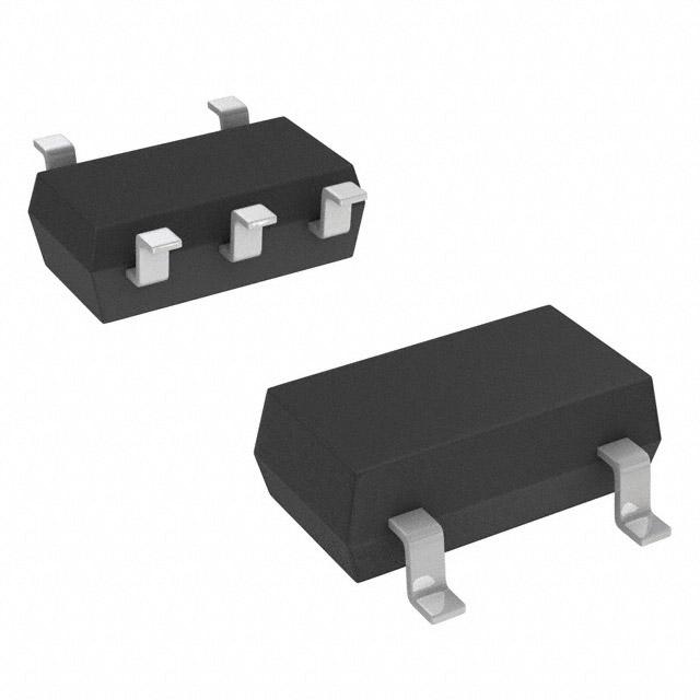
♦ Available in SOT23-5 Package
♦ Dual-Supply Operation from ±1V to ±6V
♦ Guaranteed On-Resistance:
Ω with ±5V Supplies
250Ω
♦ Guaranteed Low Off-Leakage Currents:
1nA at +25°C
10nA at +85°C
♦ Guaranteed Low On-Leakage Currents:
2nA at +25°C
20nA at +85°C
♦ Guaranteed Low Charge Injection: 10pC Max
♦ Fast Switching Speed: tON = 150ns, tOFF = 100ns
♦ CMOS-Logic Compatible Input
________________________Applications
______________Ordering Information
Battery-Operated Equipment
PART
TEMP RANGE
Audio and Video Signal Routing
MAX4503CPA
0°C to +70°C
8 Plastic DIP
Low-Voltage Data-Acquisition Systems
MAX4503CSA
MAX4503CUK
MAX4503C/D
MAX4503EPA
MAX4503ESA
MAX4503EUK
MAX4503MJA
0°C to +70°C
0°C to +70°C
0°C to +70°C
-40°C to +85°C
-40°C to +85°C
-40°C to +85°C
-55°C to +125°C
8 SO
5 SOT23-5
Dice*
8 Plastic DIP
8 SO
5 SOT23-5
8 CERDIP**
Communications Circuits
Cellular Phones
PCMCIA Cards
Modems
PIN-PACKAGE
Ordering Information continued at end of data sheet.
*Contact factory for dice specifications.
**Contact factory for availability.
___________________________________________________________Pin Configurations
TOP VIEW
COM 1
8
NO
COM 1
8
NC
N.C. 2
7
V-
N.C. 2
7
V-
N.C. 3
6
IN
N.C. 3
6
IN
5
N.C.
5
N.C.
V+ 4
MAX4503
DIP/SO
INPUT
LOW
HIGH
V+ 4
MAX4504
DIP/SO
SWITCH STATE
MAX4504
MAX4503
ON
OFF
OFF
ON
COM 1
5
V+
NO 2
V- 3
COM 1
5
V+
4
IN
NC 2
MAX4503
SOT23-5
4
IN
V- 3
MAX4504
SOT23-5
MARKING INFORMATION (SOTs ONLY)
LOT SPECIFIC CODE
XX XX
AC = MAX4503
AD = MAX4504
N.C. = NOT INTERNALLY CONNECTED
________________________________________________________________ Maxim Integrated Products
For pricing, delivery, and ordering information, please contact Maxim/Dallas Direct! at
1-888-629-4642, or visit Maxim’s website at www.maxim-ic.com.
1
MAX4503/MAX4504
General Description
�MAX4503/MAX4504
Low-Voltage, Dual-Supply, SPST,
CMOS Analog Switches
ABSOLUTE MAXIMUM RATINGS
(Voltages Referenced to V-)
V+ ..............................................................................-0.3V, +13V
Voltage into Any Terminal (Note 1) ..........-0.3V to (V+ + 0.3V) or
±10mA (whichever occurs first)
Continuous Current into Any Terminal..............................±10mA
Peak Current, NO_ or COM_
(pulsed at 1ms,10% duty cycle)...................................±20mA
Continuous Power Dissipation (TA = +70°C)
8-Pin Plastic DIP (derate 9.09mW/°C above +70°C) ...727mW
8-Pin SO (derate 5.88mW/°C above +70°C)................471mW
5-Pin SOT23-5 (derate 7.1mW/°C above +70°C) ........571mW
8-Pin CERDIP (derate 8.00mW/°C above +70°C)........640mW
Operating Temperature Ranges
MAX4503C_ _/MAX4504C_ _ .............................0°C to +70°C
MAX4503E_ _/MAX4504E_ _ ...........................-40°C to +85°C
MAX4503MJA/MAX4504MJA ........................-55°C to +125°C
Storage Temperature Range .............................-65°C to +150°C
Lead Temperature (soldering, 10sec) .............................+300°C
Note 1: Voltages on any signal terminal exceeding V+ or V- are clamped by internal diodes. Limit forward-diode current to maximum
current rating.
Stresses beyond those listed under “Absolute Maximum Ratings” may cause permanent damage to the device. These are stress ratings only, and functional
operation of the device at these or any other conditions beyond those indicated in the operational sections of the specifications is not implied. Exposure to
absolute maximum rating conditions for extended periods may affect device reliability.
ELECTRICAL CHARACTERISTICS—±5V Supply
(V+ = +4.5V to +5.5V, V- = -4.5V to -5.5V, VINH =3.5V, VINL = 1.5V, TA = TMIN to TMAX, unless otherwise noted. Typical values are at
TA = +25°C.)
PARAMETER
SYMBOL
MIN
CONDITIONS
TYP
MAX
(Note 2)
UNITS
ANALOG SWITCH
Analog Signal Range
COM to NO or NC
On-Resistance
NO or NC Off Leakage
Current (Note 3)
COM Off Leakage Current
(Note 3)
COM On Leakage Current
(Note 3)
VCOM, VNO,
VNC
RON
INO(OFF),
INC(OFF)
ICOM(OFF)
ICOM(ON)
VVCOM_ = 3.5V, ICOM = 1mA
TA = +25°C
V+
60
TA = TMIN to TMAX
V+ = 5.5V, V- = -5.5V,
VCOM_ = ±4.5V,
_
VNO or VNC = +4.5V
TA = +25°C
V+ = 5.5V, V- = -5.5V,
VCOM_ = ±4.5V,
_
VNO or VNC = +4.5V
TA = +25°C
V+ = 5.5V, V- = -5.5V,
VCOM = ±4.5V,
VNO or VNC = ±4.5V
TA = +25°C
TA = TMIN
to TMAX
TA = TMIN
to TMAX
TA = TMIN
to TMAX
250
350
-1
C, E
-10
M
-100
-1
C, E
-10
M
-100
-2
0.01
V
Ω
1
10
nA
100
0.01
1
10
nA
100
0.01
2
C, E
-20
20
M
-200
200
nA
DIGITAL I/O
IN Input Logic High
VIH
(V+) - 1.5
V+
V
IN Input Logic Low
VIL
V-
(V+) - 3.5
V
1
µA
IN Input Current Logic
High or Low
2
IIH, IIL
VIN = V+, 0V
-1
0.03
_______________________________________________________________________________________
�Low-Voltage, Dual-Supply, SPST,
CMOS Analog Switches
(V+ = +4.5V to +5.5V, V- = -4.5V to -5.5V, VINH = 3.5V, VINL = 1.5V, TA = TMIN to TMAX, unless otherwise noted. Typical values are at
TA = +25°C.)
PARAMETER
SYMBOL
CONDITIONS
MIN
TYP
(Note 2)
MAX
UNITS
SWITCH DYNAMIC CHARACTERISTICS
Turn-On Time
tON
VIN = 3V, RL = 1kΩ
VNO or VNC = 3V, Figure 1
TA = +25°C
Turn-Off Time
tOFF
VIN = 3V, RL = 1kΩ
VNO or VNC = 3V, Figure 1
TA = +25°C
Charge Injection
(Note 4)
Q
Off Isolation
VISO
NO or NC Off Capacitance
30
TA = TMIN to TMAX
150
240
20
TA = TMIN to TMAX
100
150
CL = 1nF, VNO_ = 0V, RS = 0Ω,
TA = +25°C, Figure 2
1
RL = 50Ω, CL = 15pF, VNO = 1VRMS,
f = 100kHz, TA = +25°C, Figure 3
10
ns
ns
pC


 工商网监
湘ICP备2023018690号
工商网监
湘ICP备2023018690号
