System Board 6330
MAXREFDES150# Pocket IO PLC Development Platform
Industry 4.0, the fourth revolution in manufacturing and process automation, poses a
considerable challenge for PLC design engineers who are required to pack more functionality
into enclosures that keep getting smaller. Higher I/O (input/output) density and smaller form
factors also add to the design challenge in another basic way, a consequence of the inevitable
power dissipation. The system must be more power efficient than ever to keep the PLC from
overheating, especially in an application where fans and vents are generally not acceptable.
Fortunately, new solutions are being developed by companies, such as Maxim Integrated, who
are looking to leverage their integration capabilities in the evolving industrial market.
�Features
Two analog input channels ±12V, 24-bit ADC
Two analog input channels ±24mA, 24-bit ADC
Analog output channel 0V to ±12V, 16-bit DAC
Eight digital input channels 36V (max) configurable for IEC® 61131-2 input types 1, 2, and 3
Eight digital output channels; 640mA high-side switches or 640mA push-pull at 24V
Two RS-485 COM ports; half-duplex up to 42Mbps data rate
Three DC-motor controllers: 9V to 32V full-bridge DC-motor drivers, up to 2.5A peak motor
current (supplied by separate power supply)
Four IO-Link master ports with M12 female connectors
Fully IO-Link version 1.1 compliant
TEConcept IO-Link master stack
Applications
Factory and process automation
Building automation
Robotic control
Rapidly creating and prototyping new industrial control systems
IO-Link sensors and actuators
MAXREFDES150# contents
Pocket IO: MAXREFDES150MAIN# and MAXREFDES150LED# stacked in plastic case with
Intel Edison
Connector attach board – MAXREFDES150ATACH#
40-pin female-female cable assembly–two off
USB A to micro-USB B
AC-to-DC (24VDC, 1A) power supply with adapters for regional outlets
Introduction
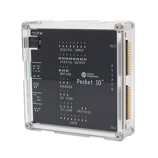
Maxim's new Pocket IO™ development platform is a reference design integrating a total of 30
IO's consisting of four analog inputs, one analog output, eight digital inputs, eight digital
outputs, two RS485 (Profibus-capable field busses), three encoder motor-control ports, and
four IO-Link® masters. Maxim’s Pocket IO technology demonstration platform shows how
analog integration can enable lower heat dissipation and faster throughput in a footprint that is
less than ten cubic inches. Pocket IO connectivity is through USB or its own Wi-Fi® network.
Code can be developed to run on the Intel® Edison using the popular and easy to use opensource Arduino®software IDE.
Detailed Description of Hardware
Pocket IO is the brand name for MAXREFDES150#. The MAXREFDES150# consists of three
different boards. The overall system block diagram is shown in Figure 1.
�Figure 1. MAXREFDES150# system block diagram.
The ICs for the main functional blocks are within the Pocket IO case (the two boards are
MAXREFDES150MAIN# and MAXREFDES150LED#) while the connectors are on a separate
board (called MAXREFDES150ATACH#) which connects to Pocket IO using two 40-pin cable
assemblies.
The control program for Pocket IO runs on the Intel Edison board, which is mounted on the
MAXREFDES150MAIN# board. Separate STM microcontrollers are used to support the IOLink masters (TEConcepts stack) and the DC-motor drivers.
�Power Supplies
A single 24V, 1A supply is used to power the Pocket IO and internal DC-DC, and LDO circuits
are used to generate the various different voltage levels required by the analog and digital
devices. Note: The maximum load this adapter can supply is 1A, which limits how many of
the digital outputs are switching loads simultaneously since each of the eight outputs can
handle loads of up to 640mA each. The user can use a different 24V supply with 5A (max)
capacity. The 24V, 1A supply connects to the block barrel connector, shown on the left in
Figure 2.
Pocket IO has three DC-motor controllers, each of which can support +9V to +32V full-bridge
DC-motor drivers at up to 2.5A peak motor current. In order to support these higher voltages
and currents, a separate user-supplied power supply is required, and connects to Pocket IO
through the green three-way terminal. Terminal 1 is used (with Terminal 3) to test the polarity
of the external supply (to protect Pocket IO motor drivers from reverse polarity connections).
In normal-use mode Terminal 2 is the +9V to +32V connection and Terminal 3 is the ground
or 0V connection.
Figure 2. MAXREFDES150# power inputs.
Connections
The main functional blocks are on the two PCBs within the Pocket IO case while the
connectors are on a separate board, called MAXREFDES150ATACH# shown in Figure 3.
Figure 3. MAXREFDES150ATACH#.
�LED Indicators
Figure 4 explains the functions of the LED indicators for MAXREFDES150#.
Figure 4. Pocket IO LEDs.
Detailed Description of Software
When building up a quick application, or when prototyping some feature, the quickest and
easiest way to program Pocket IO, is through the Arduino application. Though not a full-code
development, debugging environment, the Arduino sketch technique has a lot to offer,
including:
A familiar interface, instantly recognizable by many
A full C/C++ compiler
Access to many useful features built into the Linux OS resident in the Intel Edison processor
Access to Pocket IO features through an included library
Access to library updates as they become available
With so much capability packed into one small enclosure, the interface to manage all this is
crucial. Each of Pocket IO's 10 resources has its own API. Figure 5 shows the software
architecture for Pocket IO using Arduino IDE to compile code to run on the onboard Intel
Edison CPU.
�Figure 5. Pocket IO software architecture.
The following sections are details about API and some techniques, many Linux-specific, that
enhance the capability of your applications.
Detailed Pocket IO API
These sections, organized alphabetically by Pocket IO feature, details the API available to
control Pocket IO through sketch.
Note: For information about how to access software revision codes from Pocket IO, consult
Boardinfo.ino in the Pio section of the Examples in sketch.
Analog Input
Pocket IO features two analog voltage inputs and two analog current inputs, all easily
accessible through sketch. The voltage channels read anything between -12V and +12V
whereas the current channels read anything between -24mA and +24mA. Pocket IO features
a MAX11254 24-bit ADC featuring built-in two-point calibration compensation, which the API
accommodates.
�The API selects from among four channels, as follows:
Channel
API Mnemonic
Attach Board Symbol
First Voltage
AI0
AI0+/AI0-
Second Voltage
AI1
AI1+/AI1-
First Current
AI2
AI2 AI2+/AI2-
Second Current
AI3
AI3 AI3+/AI3-
Note: The analog input and output circuitry grounds are isolated from
the ground of the rest of Pocket IO. The AGND labels on the attach
board indicate this separate analog ground. If you accidentally return
an analog signal, either from one of the analog inputs or from the
analog output, to the more common GND, there can be unexpected
results.
Calibration
The following code snippet shows how to perform a two-point
calibration. Commonly, the user locks in the calibration, so it does not
need to be done again, and calibration rarely needs to be done.
Calibration comes in handy when attaching further circuitry to the
analog inputs, and accuracy is to be maintained ahead of this extra
circuitry. Pocket IO comes factory-calibrated for best accuracy at the
connection points of the attach board.
The code snippet uses port AI0 as an example, but the code is the
same regardless of which port is being calibrated. Each channel keeps
its own unique calibration parameters.
// Makes Pocket IO analog input API available
// #include
PioAi pioAi; // Instances an analog input interface object
pioAi.init(); // Always needed for analog input pioAi.initCal(AI0); //Commences calibration
/*
* Put code here to apply +12 volts at the point of calibration
* if channel AI0 or channel AI1, or to apply +24mA if channel
* AI2 or AI3.
�*
* Do not proceed until the voltage or current is applied and * stable.
*/
pioAi.setFullCal(AI0); // +12V or +24mA measured
/*
* Put code here to apply 0 volts or 24mA at the point of
* calibration.
*
* Do not proceed until the voltage or current is applied and * stable.
*/
pioAi.setZeroCal(AI0); // 0V or 24mA measured
delay(1000); // needed for ADC to calc corrections
// This method call takes the required corrections for that
// channel and stores it in nonvolatile memory
pioAi.storeCal(AI0);
Reading an Analog Sample
Samples can be read either as a float or as a raw binary code from the
ADC. The following code snippet shows how it is done. Because the
sample rate is determined by the ADC itself, the user must select from
one of the MAX11254 sample times as shown in the following table.
Longer sample times result in readings with lower noise. This affects
multiple sample reads. For example, with AI_RATE_1_9_SPS, after a
first read, the thread calling a read method a second time is blocked for
about 526msec.
MAX11254 Sample Rate (sps)
API Mnemonic
1.9
AI_RATE_1_9_SPS
15.6
AI_RATE_15_6_SPS
31.2
AI_RSTE_31_2_SPS
62.5
AI_RATE_62_5_SPS
250
AI_RATE_250_SPS
500
AI_RATE_500_SPS
1000
AI_RATE_1000_SPS
�// Makes Pocket IO analog input API available
//
#include // no init() method
PioAi pioAi; // instances an analog input interface object
pioAi.init(); // always needed for analog input
// Loads a previously stored calibration for that channel,
// usually done once at setup
//
pioAi.restoreCal(AI0);
>while (XXX)
{
>// Reads one sample as a raw binary code
//
uint32_t code = pioAi.readCode(AI0, AI_RATE_1_9_SPS);
// The returned code is in offset binary, where 0V is
// 2^23, 12V is 2^23+2^23 = 2^24, and 12V is // 2^23 – 2^23 = 0
//
// In the case of current, the calibration is done is
// firmware, so the returned code is not relevant
// float toVolts = (float) (code – 8388608) * 12.0 / 8388608;
// Or you can do it easier this way, for reading current,
// this is the best way.
// float volts = pioAi.readFloat(AI0, AI_RATE_1_9_SPS);
}
Analog Output
Pocket IO provides one analog output, capable of any output voltage
between 0V and 12V. Since there is only one analog output channel,
there is no need to select channels. The API consists of only one
method call, and no init() is needed for analog out.
�The call to the method is a raw 16-bit code to the DAC. To drive a
specific voltage, it must first be converted to a 16-bit equivalent for the
DAC, as shown in the code snippet below.
// Makes Pocket IO analog output API available
// #include PioAo pioAo;
// instances an analog output interface object
const float DAC_CONV = 5443.106; // codes per volt
float voltageOut = 1.250; // desired output voltage
uint16_t codeDAC = (uint16_t) (voltageOut * DAC_CONV);
// Returns the argument to the method, as a uint16_t, which
// is usually ignored
//
uint16_t intCodeDAC = pioAo.writeCode(codeDAC);
// Could also do it this way
// uint16_t intCodeDAC = pioAo.writeCode(voltageOut * DAC_CONV);
Communications (RS-485)
Pocket IO provides serial communication through two RS-485 ports.
Each port is half-duplex, and is preset for 115.2KBAUD at 8N2 (eight
data bits, no parity, two stop bits).
Select from among the 2 channels as follows:
Channel
API Mnemonic
Attach Board Symbol
0
COM0
COM0A/COM0B
1
COM1
COM1A/COM1B
The API permits independent reading and writing for each channel. For
any given channel, writes supersede reads. No harm occurs if multiple
RS-485 transceivers drive a bus at the same time though this means
any received data would be corrupted. Use protocol to ensure only one
transceiver drives the bus at a time.
// Makes Pocket IO COMMS API available
// #include PioCom
pioCom; // instances a COMMS interface object
pioCom.init(); // always needed for COMMS
�uint8_t bytes = {‘H’, ‘e’, ‘l’, ‘l’, ‘o’, ‘,’,’ ‘, ‘W’, ‘o’, ‘r’, ‘l’, ‘d’, ‘!’, \0};
// First param must be either COM0 or COM1
// Second param is a pointer to an array of bytes
// Third param is the number of bytes to transfer
//
// Maximum of 128 bytes can be sent. If a previous write
// has not yet completed, then the number of bytes that
// can be written is 128 – (number of bytes left to send)
// // If you send more than 128 bytes, the transmitted data
// will be corrupted. // PioCom.write (COM0, bytes, sizeof(bytes));
Reading data from an RS-485 port is similar to writing, with the added
complication that you do not necessarily know how many bytes have
been received. The following code snippet shows how to read data.
// Makes Pocket IO COMMS API available
//
#include PioCom pioCom;
// instances a COMMS interface object pioCom.init();
// always needed for COMMS
// Needed once before first read
// pioCom.clearInterrupts(COM0); uint8_t receiveBuffer [100]; uint8_t receiveCount;
// First param must be either COM0 or COM1
// Second param is an array to receive data
// Third param is the size of the buffer
// Fourth param will get the number of bytes actually read
//
// The receive buffer will be filled with a number of bytes
// received since a previous read method call. If this is less
// than the size of the buffer, then the buffer is
// partially filled. Otherwise, the buffer is filled and
�// a subsequent read can obtain further read data.
//
// Note that data will be corrupted if more than 128 bytes
// have been received since a previous read method call.
//
// If there is no data, the fourth param will be set to zero
//
pioCom.read(COM0, receiveBuffer,
sizeof(receiveBuffer), &receiveCount);
// Do you want to test if there is pending data to be
// received? This method call returns the number of // bytes waiting to be read
//
// Useful for conditional mutex
//
uint8_t howManyBytes = pioCom.readRxFifoLevel(COM0);
Digital Input
Pocket IO has eight individual IEC-compliant industrial digital inputs.
These inputs connect to binary sensors, such as limit switches,
proximity sensors, distance sensors, and user switches. These inputs
can be read individually, or as a group, through sketch.
Eight LEDs on the display panel indicate the state of each of these
digital inputs. The LEDs are extinguished if driven low or left open, and
illuminate when the corresponding input is driven logic high. The
following table connects the individual inputs to the values returned
through the API
Channel
Bit Mask
API Mnemonic
Attach Board Symbol
1
0x01
DI1
DI1
2
0x02
DI2
DI2
3
0x04
DI3
DI3
4
0x08
DI4
DI4
5
0x10
DI5
DI5
6
0x20
DI6
DI6
�7
0x40
DI7
DI7
8
0x80
DI8
DI8
Additionally, the user has access to the debounce feature of the
MAX31913 industrial digital input device. This feature reduces
chattering of particularly noisy digital inputs. This debounce is global,
applying to all digital inputs simultaneously used by Pocket IO. The
following code snippet shows how to access these inputs as well as
how to manage debounce.
// Makes Pocket IO digital input API available
//
#include PioDi pioDi;
;// Instances a DI interface object pioDi.init();
pioDi.init(); // always needed for DI
// Gets all 8 inputs at once, correspondence between
;
// bits and inputs given in the table above
// uint8_t allDigitalInputs = pioDi.readInput();
// Overloaded method also reads individual digital input
// channels. Returns ‘0’ or ‘1’
//
// In this case, checks the state of channel 7 only
// uint8_t specificDigitalInput = pioDi.readInput(DI7);
// This is how to set the debounce. Set as follows:
// 0x00 – no debounce
// 0x01 – 25usec of debounce
�// 0x02 – 750usec of debounce
// 0x03 through 0xff – 3msec of debounce
//
// A possibly corrected value is returned, for example if you
// try to set 0x10, 0x03 will be returned
// uint8_t realDebounce = pioDi.writeDebounce(0x02);
// The currently operational debounce setting can be checked
// uint8_t whichDeboucne = pioDi.readDebounce();
Digital Output
Pocket IO supports eight industrial digital outputs, each capable of
driving 24V at greater than 640mA. The API supports many of the
features of the MAX14913 or MAX14912 digital output driver IC,
including output modes and fault detection.
Each digital output channel can be in one of two modes. High-side
mode, as its name implies, only drives a channel high (nominal 24V).
Many existing actuators and indicators work best in high-side mode. To
have faster output driver switching, each output channel can also be
configured to push-pull mode. Since both a high and a low are actively
driven, there is no longer a natural decay of the wiring slowing down
the transitions from high to low. The following table shows how to
specify these through the API.
Mode
API Mnemonic
High-Side
HS_MODE
Push-Pull
PP_MODE
Each individual digital output can be driven high or low. The Pocket IO
front panel allows easy confirmation of the output state, illuminating a
green LED for each output being driven high. A matching red LED
indicates that a fault has occurred on that output. This most commonly
happens when accidentally tying two digital outputs together when they
drive conflicting logic levels.
Channel
Bit Mask
API Mnemonic
Attach Board Symbol
1
0x01
DO1
DO1
2
0x02
DO2
DO2
3
0x04
DO3
DO3
�4
0x08
DO4
DO4
5
0x10
DO5
DO5
6
0x20
DO6
DO6
7
0x40
DO7
DO7
8
0x80
DO8
DO8
The following code snippets show how to command the digital outputs
and manage the mode settings of Pocket IO.
// Makes Pocket IO digital output API available
// #include PioDo pioDo;
// instances a DO interface object
// no init() method
// Commonly, set the output mode once before
// driving outputs
//
// first param:
// 0x00 means set all to highside more
// 0x01 – 0xff means set all to pushpull mode
// pioDo.setModeAll(PP_MODE);
// can also set the mode of individual outputs
// here, half of the outputs are set to highside
// for (int i = DO5; i