MAXREFDES37# IO-Link Servo Driver
Quick Start Guide
Rev 0; 4/15
For pricing, delivery, and ordering information, please contact Maxim Direct at 1-888-629-4642, or visit Maxim Integrated’s website at www.maximintegrated.com.
Maxim Integrated cannot assume responsibility for use of any circuitry other than circuitry entirely embodied in a Maxim Integrated product. No circuit
patent licenses are implied. Maxim Integrated reserves the right to change the circuitry and specifications without notice at any time.
© 2015 Maxim Integrated Products, Inc.
Maxim Integrated and the Maxim Integrated logo are trademarks of Maxim Integrated Products, Inc.
�MAXREFDES37# IO-Link Servo Driver Quick Start Guide
Table of Contents
1.
Required Equipment ................................................................................................ 3
2.
Overview .................................................................................................................. 5
3.
Procedure ................................................................................................................ 6
4.
Trademarks ............................................................................................................ 15
5.
Revision History ..................................................................................................... 16
2
�MAXREFDES37# IO-Link Servo Driver Quick Start Guide
1. Required Equipment
0B
•
•
•
•
PC with Windows® 7 or Windows 8 (Verify with TEConcept that your version
of Windows is supported before purchasing their software license. See
Section 4 Software License Keys of the MAXREFDES79# IO-Link Master
Quick Start Guide.)
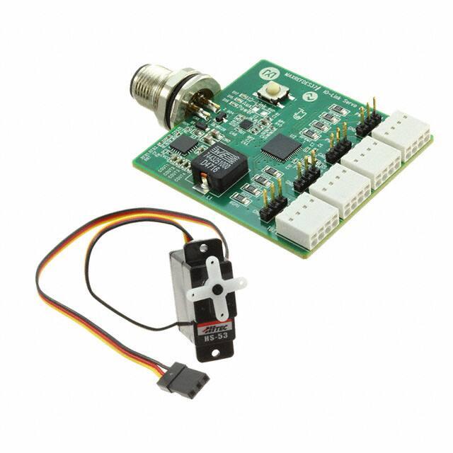
MAXREFDES37# (Box Contents)
o MAXREFDES37# board
o Hitec HS-53 servo motor
MAXREFDES79# (Box Contents)
o MAXREFDES79# 4-Port IO-Link® Master
o AC-to-DC 24V/1A output power converter
o USA-to-Euro power adapter
o Two Black IO-Link cables (1 meter)
o Micro-USB cable (2 meters)
Necessary downloadable software includes:
o TEConcept IO-Link Control Tool (CT) Software (see note)
o STM32F4 VCP Driver (see note)
Note: Download files from the Design Resources tab at:
www.maximintegrated.com\MAXREFDES37
www.maximintegrated.com\MAXREFDES79
Figure 1. MAXREFDES37# box contents.
3
�MAXREFDES37# IO-Link Servo Driver Quick Start Guide
Figure 2. MAXREFDES79# box contents.
Figure 3. MAXREFDES37# system connected to MAXREFDES79#.
4
�MAXREFDES37# IO-Link Servo Driver Quick Start Guide
2. Overview
1B
1. Install the TEConcept CT software (TC_Installer.msi).
2. Install the STM32F4 VCP driver.
3. Connect the Micro-USB cable from the PC to the MAXREFDES79#.
4. Connect the AC-to-DC 24V DC power converter.
5. Connect the MAXREFDES37# to Port 1 of the MAXREFDES79# IO-Link
master.
6. Connect the Hitec HS-53 servo motor to header H1 (PWM1) on the
MAXREFDES37#.
7. Run the TEConcept CT software and connect to the MAXREFDES79#.
8. Load in the IODD file for your sensor or actuator.
9. Press the IO-Link button to connect to sensor or actuator.
10. Read and write to sensor or actuator parameters.
5
�MAXREFDES37# IO-Link Servo Driver Quick Start Guide
3. Procedure
2B
1. Download the TEConcept CT software and STM32F4 VCP driver from the
Design Resources tab at www.maximintegrated.com/MAXREFDES79.
2. Install the TEConcept CT software (TC_Installer.msi).
3. Install the appropriate STM32F4 VCP driver depending on the version of
Windows operating system (32-bit or 64-bit) as shown in Figure 4.
Figure 4. STM32F4 VCP Driver for 32-bit and 64-bit Windows 7/Windows 8.
4. Connect the Micro-USB cable from the PC to the MAXREFDES79# as shown
in Figure 5.
Figure 5. Connect the Micro-USB cable from underneath the
MAXREFDES79# and then connect it to the PC.
6
�MAXREFDES37# IO-Link Servo Driver Quick Start Guide
5. Ensure that switch SW1 is in the “Down” or “In” position as shown in Figure 6.
Figure 6. Verify the SW1 position and connect the AC-to-DC 24V DC power
converter.
6. Connect the AC-to-DC 24V DC power converter as shown in Figure 6.
7. Connect the MAXREFDES37# to Port 1 of the MAXREFDES79# IO-Link
master. Port 1 is the top M12 female connector on the LED side of the IO-Link
master.
8. Connect the Hitec HS-53 servo motor to header H1 on the MAXREFDES37# as
shown in Figure 1.
7
�MAXREFDES37# IO-Link Servo Driver Quick Start Guide
9. Open Windows Device Manager and verify the connected COM port number
connected as STMicroelectronics Virtual COM Port (COMx) shown in
Figure 7.
Figure 7. Verify COM port connected as “STMicroelectronics Virtual COM Port
(COMx).” It may be a different COM port number on your PC.
8
�MAXREFDES37# IO-Link Servo Driver Quick Start Guide
10. Run the TEConcept CT software as shown in Figure 8. Press the connection
settings icon, which is a gray gear. (COM port may be different on your PC.)
Press the Connect button and it will show a flashing green COM connection
label at the bottom of the GUI once connected.
Figure 8. TEConcept IO-Link CT Software. Tested with version 1.0.60.0.
9
�MAXREFDES37# IO-Link Servo Driver Quick Start Guide
11. Load in the IODD file for the MAXREFDES37#. First, press the Select device
button. In the Device selector window, press the Import button and select the
sensor’s *1.1.xml IODD file. Highlight the IODD file in the IO-Link Devices box
and press the Select device button. See Figure 9 and Figure 10.
Figure 9. Sensor IODD file (*1.1.xml).
10
�MAXREFDES37# IO-Link Servo Driver Quick Start Guide
Figure 10. Press the Select device button when imported IODD files are
highlighted.
11
�MAXREFDES37# IO-Link Servo Driver Quick Start Guide
12. The IO-Link button becomes active once the IODD file is assigned to a port
and the MAXREFDES79# is connected to the PC. Press the IO-Link button
once it becomes active as shown in Figure 11.
Figure 11. IO-Link button becomes active once an IODD is assigned to a port and
the MAXREFDES79# is connected to the PC.
12
�MAXREFDES37# IO-Link Servo Driver Quick Start Guide
13. Manually move the servo motor to the 0-degree position by typing -100 into the
Servo 1 Process data scroll box as shown in Figure 12. Next, press the
Actualize PD out button to send the value to the MAXREFDES37#. Next,
manually move the servo motor to the 90-degree position by typing 100 into
the Servo 1 Process data scroll box (first time was -100, this time is 100).
Then press the Actualize PD out button again to send the value to the
MAXREFDES37#.
Figure 12. Manually changing Servo 1 position using process data
output.
13
�MAXREFDES37# IO-Link Servo Driver Quick Start Guide
14. Select (0x0067) Servo 1 mode in the Parameters box and then use the dropdown menu to change the parameter value to (1) triangle slow. Lastly, press
the Write button to send the value change to the MAXREFDES37# as shown
Figure 13. Experiment with other Servo modes such as (2) triangle fast, (3)
rectangle, (4) sawtooth rising, or (5) sawtooth falling.
Figure 13. Changing Servo 1 mode to (1) triangle slow.
14
�MAXREFDES37# IO-Link Servo Driver Quick Start Guide
4. Trademarks
3B
IO-Link is a registered trademark of ifm electronic GmbH.
Windows is a registered trademark and registered service mark of Microsoft Corp.
15
�MAXREFDES37# IO-Link Servo Driver Quick Start Guide
5. Revision History
4B
REVISION
NUMBER
0
REVISION
DATE
4/15
DESCRIPTION
Initial release
PAGES
CHANGED
—
16
�
很抱歉,暂时无法提供与“MAXREFDES37#”相匹配的价格&库存,您可以联系我们找货
免费人工找货