Page 1 of 6
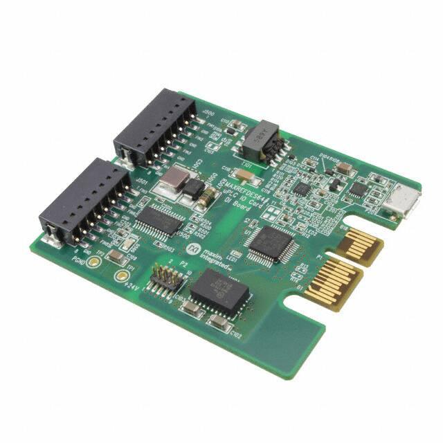
MAXREFDES64# System Board
Enlarge+
Introduction
Industry 4.01 marks the fourth industrial revolution, characterized by distributed, intelligent
control systems. Breaking from a past with large, centralized programmable-logic
controllers, Industry 4.0 allows for highly configurable, highly modular factories, which
accept an ever increasing number of sensor inputs while operating at a higher output than
ever before. The ultra-small PLC, or Micro PLC, lies at the heart of the Industry 4.0 factory,
providing high performance with ultra-low power consumption, in an ultra-small package.
The MAXREFDES64# is Maxim’s Micro PLC, octal-channel, digital input card.
The MAXREFDES64# reference design features 8-channel digital inputs with isolated
power and data. The design integrates a 600VRMS data isolator (MAX14850); a STM32F1
microcontroller; a FTDI USB-UART bridge; a high-efficiency DC-DC converter
(MAX17515); and isolated/regulated +24V and +5V power rails (MAX17498C). The entire
system typically operates at less than 140mW and fits into a space roughly the size of a
credit card. A block diagram of the system is shown in Figure 1.
�Page 2 of 6
Figure 1. The MAXREFDES64# reference design block diagram.
Applications
Features
•
•
•
•
Isolated power and data
Micro PLC form factor
Device drivers
Example C source code
• Industrial control and automation
• Process control
• PLC
Detailed Description of Hardware
The power requirement is shown in Table 1.
Table 1. Power Requirement for the MAXREFDES64# Reference Design
Power Type
Input Voltage (V)
Input Current (mA, typ)
On-board isolated power
24
5.6
Note: STM32 and FTDI are powered by USB separately.
The MAX31913 (U500) is an octal digital input serializer.
The ultra-efficient MAX17498C (U102) generates the isolated +24V, and +5V rails from a
24V supply. The MAX14850 (U301) digital data isolators provide data isolation. The
combined power and data isolation achieved is 600VRMS.
The MAX17515 (U101) step-down DC-DC converter converts the +5V supply from the
USB to +3.3V and powers the STM32 (U1) microcontroller and FTDI (U201) USB-UART
bridge.
Detailed Description of Firmware
�Page 3 of 6
The MAXREFDES64# uses the on-board STM32F1 microcontroller to communicate with
the octal digital input serializer. The user can read the digital inputs status through a
terminal program. The simple process flow is shown in Figure 2. The firmware is written in
C using the Keil µVision5 tool.
Figure 2. The MAXREFDES64# firmware flowchart.
The complete source code is provided to speed up customer development. Code
documentation can be found in the corresponding firmware platform files.
Quick Start
Required equipment:
• Windows® PC with a USB port
• MAXREFDES64# board
• 24V power supply
Procedure
The reference design is fully assembled and tested. Follow the steps to verify board
operation:
Always disconnect and reconnect the USB cable before using the terminal program.
1. Turn off, or keep off, the 24V power supply.
2. The MAXREFDES64# utilizes the FTDI USB-UART bridge IC. If Windows cannot
automatically install the driver for the FTDI USB-UART bridge IC, the driver is
available for download from www.ftdichip.com/Drivers/D2XX.htm.
3. Connect the negative terminal of the 24V power supply to the PGND connector on
the MAXREFDES64# board. Connect the positive terminal of the 24V power supply
to the +24V connector on the MAXREFDES64# board.
�Page 4 of 6
4. Turn on the 24V power supply.
5. Connect the USB cable from the PC to the MAXREFDES64# board.
6. Open Hyperterminal or a similar Terminal program on the PC. Find the appropriate
COM port, usually a higher number port, such as COM4, or COM6, and configure
the connection for 921600, n, 8, 1, none (flow control).
7. The MAXREFDES64# software will display a menu (Figure 3).
8. For immediate signal testing, connect the positive terminal of the 24V voltage source
to any digital input terminal (DI_FIN1 to DI_FIN8) of the J500 and J501 terminal
blocks. Pay close attention and avoid connecting 24V to the ground terminals. Since
the digital input terminals and the ground terminals alternate on the terminal block
and are so close to each other, special care must be taken.
9. Press 0 in the terminal program to start the continuous read mode.
10. Verify that the digital value read (hex and binary) matches the digital input status of
J500 and J501 terminal blocks.
Figure 3. Terminal program main menu.
Lab Measurements
Figure 4 and Figure 5 show the digital inputs of hex value 0x55 and also the result read
by the Terminal program.
�Page 5 of 6
Figure 4. Test setup.
Figure 5. Test outputs.
Reference
1. The new generation of manufacturing production is called Industry 4.0 in Germany
and Smart Manufacturing System elsewhere. See, Securing the future of German
manufacturing industry, Recommendations for implementing the strategic
initiative INDUSTRIE 4.0, Final report of the Industrie 4.0 Working Group,
�Page 6 of 6
Industry 4.0 Working Group, Acatech National Academy of Science and Engineering,
April 2013,
www.acatech.de/fileadmin/user_upload/Baumstruktur_nach_Website/Acatech/root/de/Material_fuer_Sonderseiten/
Industrie_4.0/Final_report__Industrie_4.0_accessible.pdf. Henceforth cited as
Industrie 4.0. Although the Industrie 4.0 report is focused on Germany, the
implications of the German research and findings are recognized for industry in other
countries. See also Ferber, Stefan, “Industry 4.0 – Germany takes the first steps
toward the next industrial revolution,” Bosch Software Group, Blogging the Internet
of Things, October 16, 2013, http://blog.bosch-si.com/industry-4-0-germany-takesfirst-steps-toward-the-next-industrial-revolution/.
There are many sources for Smart Manufacturing Leadership. An interesting
summary report of issues and topics can be found at the Smart Manufacturing
Leadership Coalition Committee Working Meeting, Minneapolis, MN, U.S.,
Thursday, October 20, 2011, https://smart-processmanufacturing.ucla.edu/workshops/2011-workshop/presentations/SMLC%2010-2011v3.pdf. Also see, Implementing 21st Century Smart Manufacturing, Workshop
Summary Report, Smart Manufacturing Leadership Coalition, June 24, 2011,
https://smart-process-manufacturing.ucla.edu/about/news/Smart%
20Manufacturing%206_24_11.pdf. A simple web search on the topic will reveal
considerably more references.
Windows is a registered trademark and registered service mark of Microsoft Corporation.
http://www.maximintegrated.com/en/design/reference-design-center/system-board/5983.html
12/8/2014
�