OP295

OP295

  • 厂商:

    AD(亚德诺)

  • 封装:

  • 描述:

    OP295 - Dual/Quad Rail-to-Rail Operational Amplifiers - Analog Devices

  • 详情介绍
  • 数据手册
  • 价格&库存
OP295 数据手册
Dual/Quad Rail-to-Rail Operational Amplifiers OP295/OP495 FEATURES Rail-to-rail output swing Single-supply operation: 3 V to 36 V Low offset voltage: 300 μV Gain bandwidth product: 75 kHz High open-loop gain: 1000 V/mV Unity-gain stable Low supply current/per amplifier: 150 μA maximum PIN CONFIGURATIONS OUT A –IN A +IN A V– 1 2 3 4 8 V+ OUT B 00331-001 00331-004 TOP VIEW (Not to Scale) OP295 7 6 5 –IN B +IN B Figure 1. 8-Lead Narrow-Body SOIC_N (S Suffix) APPLICATIONS Battery-operated instrumentation Servo amplifiers Actuator drives Sensor conditioners Power supply control OUT A –IN A +IN A V– 1 2 3 4 OP295 8 7 6 5 V+ OUT B 00331-002 00331-003 –IN B +IN B Figure 2. 8-Lead PDIP (P Suffix) GENERAL DESCRIPTION Rail-to-rail output swing combined with dc accuracy are the key features of the OP495 quad and OP295 dual CBCMOS operational amplifiers. By using a bipolar front end, lower noise and higher accuracy than those of CMOS designs have been achieved. Both input and output ranges include the negative supply, providing the user with zero-in/zero-out capability. For users of 3.3 V systems such as lithium batteries, the OP295/OP495 are specified for 3 V operation. Maximum offset voltage is specified at 300 μV for 5 V operation, and the open-loop gain is a minimum of 1000 V/mV. This yields performance that can be used to implement high accuracy systems, even in single-supply designs. The ability to swing rail-to-rail and supply 15 mA to the load makes the OP295/OP495 ideal drivers for power transistors and H bridges. This allows designs to achieve higher efficiencies and to transfer more power to the load than previously possible without the use of discrete components. For applications such as transformers that require driving inductive loads, increases in efficiency are also possible. Stability while driving capacitive loads is another benefit of this design over CMOS rail-to-rail amplifiers. This is useful for driving coax cable or large FET transistors. The OP295/OP495 are stable with loads in excess of 300 pF. OUT A –IN A +IN A V+ +IN B –IN B OUT B 1 2 3 4 5 6 7 14 13 12 OUT D –IN D +IN D V– +IN C –IN C OUT C OP495 11 10 9 8 Figure 3. 14-Lead PDIP (P Suffix) OUT A –IN A +IN A V+ +IN B –IN B OUT B NC 1 2 3 4 5 6 7 8 16 15 OUT D –IN D +IN D V– +IN C –IN C OUT C NC TOP VIEW (Not to Scale) OP495 14 13 12 11 10 9 NC = NO CONNECT Figure 4. 16-Lead SOIC_W (S Suffix) The OP295 and OP495 are specified over the extended industrial (−40°C to +125°C) temperature range. The OP295 is available in 8-lead PDIP and 8-lead SOIC_N surface-mount packages. The OP495 is available in 14-lead PDIP and 16-lead SOIC_W surface-mount packages. Rev. E Information furnished by Analog Devices is believed to be accurate and reliable. However, no responsibility is assumed by Analog Devices for its use, nor for any infringements of patents or other rights of third parties that may result from its use. Specifications subject to change without notice. No license is granted by implication or otherwise under any patent or patent rights of Analog Devices. Trademarks and registered trademarks are the property of their respective owners. One Technology Way, P.O. Box 9106, Norwood, MA 02062-9106, U.S.A. Tel: 781.329.4700 www.analog.com Fax: 781.461.3113 ©2006 Analog Devices, Inc. All rights reserved. OP295/OP495 TABLE OF CONTENTS Features .............................................................................................. 1 Applications....................................................................................... 1 General Description ......................................................................... 1 Pin Configurations ........................................................................... 1 Revision History ............................................................................... 2 Specifications..................................................................................... 3 Electrical Characteristics............................................................. 3 Absolute Maximum Ratings............................................................ 5 Thermal Resistance ...................................................................... 5 ESD Caution.................................................................................. 5 Typical Performance Characteristics ............................................. 6 Applications....................................................................................... 9 Rail-to-Rail Application Information........................................ 9 Low Drop-Out Reference ............................................................ 9 Low Noise, Single-Supply Preamplifier ..................................... 9 Driving Heavy Loads ................................................................. 10 Direct Access Arrangement ...................................................... 10 Single-Supply Instrumentation Amplifier .............................. 10 Single-Supply RTD Thermometer Amplifier ......................... 11 Cold Junction Compensated, Battery-Powered Thermocouple Amplifier .......................................................... 11 5 V Only, 12-Bit DAC That Swings 0 V to 4.095 V.................... 11 4 to 20 mA Current-Loop Transmitter.................................... 12 3 V Low Dropout Linear Voltage Regulator............................. 12 Low Dropout, 500 mA Voltage Regulator with Foldback Current Limiting ........................................................................ 12 Square Wave Oscillator.............................................................. 13 Single-Supply Differential Speaker Driver.............................. 13 High Accuracy, Single-Supply, Low Power Comparator ...... 13 Outline Dimensions ....................................................................... 14 Ordering Guide .......................................................................... 16 REVISION HISTORY 5/06—Rev. D to Rev. E Updated Format..................................................................Universal Changes to Features.......................................................................... 1 Changes to Pin Connections........................................................... 1 Updated Outline Dimensions ....................................................... 14 Changes to Ordering Guide .......................................................... 15 2/04—Rev. C to Rev. D Changes to General Description .................................................... 1 Changes to Specifications ................................................................ 2 Changes to Absolute Maximum Ratings ....................................... 4 Changes to Ordering Guide ............................................................ 4 Updated Outline Dimensions ....................................................... 12 3/02—Rev. B to Rev. C Figure changes to Pin Connections ................................................1 Deleted OP295GBC and OP495GBC from Ordering Guide ......3 Deleted Wafer Test Limits Table......................................................3 Changes to Absolute Maximum Ratings........................................4 Deleted Dice Characteristics............................................................4 Rev. E | Page 2 of 16 OP295/OP495 SPECIFICATIONS ELECTRICAL CHARACTERISTICS VS = 5.0 V, VCM = 2.5 V, TA = 25°C, unless otherwise noted. Table 1. Parameter INPUT CHARACTERISTICS Offset Voltage Input Bias Current Input Offset Current Input Voltage Range Common-Mode Rejection Ratio Large Signal Voltage Gain Offset Voltage Drift OUTPUT CHARACTERISTICS Output Voltage Swing High Symbol VOS −40°C ≤ TA ≤ +125°C IB −40°C ≤ TA ≤ +125°C IOS −40°C ≤ TA ≤ +125°C VCM CMRR AVO ΔVOS/ΔT VOH RL = 100 kΩ to GND RL = 10 kΩ to GND IOUT = 1 mA, −40°C ≤ TA ≤ +125°C RL = 100 kΩ to GND RL = 10 kΩ to GND IOUT = 1 mA, −40°C ≤ TA ≤ +125°C 4.98 4.90 0 V ≤ VCM ≤ 4.0 V, −40°C ≤ TA ≤ +125°C RL = 10 kΩ, 0.005 ≤ VOUT ≤ 4.0 V RL = 10 kΩ, −40°C ≤ TA ≤ +125°C 0 90 1000 500 110 10,000 1 5.0 4.94 4.7 0.7 0.7 90 ±18 110 150 0.03 75 86 1.5 51
OP295
物料型号: - OP295/OP495:Dual/Quad Rail-to-Rail Operational Amplifiers,即双/四路轨到轨运算放大器。

器件简介: - OP495是四路轨到轨运算放大器,而OP295是双路轨到轨运算放大器。它们结合了低噪声和轨到轨输出摆动的特点,适用于单电源供电,供电范围从3V到36V。

引脚分配: - 
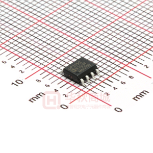
8引脚Narrow-Body SOIC_N(S后缀)、8引脚PDIP(P后缀)、14引脚PDIP(P后缀)和16引脚SOIC_W(S后缀)。

参数特性: - 轨到轨输出摆动; - 单电源运行:3V至36V; - 低失调电压:300μV; - 增益带宽积:75kHz; - 高开环增益:1000V/mV; - 低供电电流:每个放大器最大150μA。

功能详解: - 这些放大器能够在轨到轨输出摆动的同时保持直流精度,通过双极性前端实现比CMOS设计更低的噪声和更高的精度。 - 最大偏置电压在5V工作条件下为300μV,开环增益至少为1000V/mV,适用于实现高精度系统,甚至是单电源设计。 - 能够摆动到轨到轨并为负载提供15mA电流,使其成为理想的功率晶体管和H桥驱动器。 - 这些放大器在超过300pF的负载下稳定,适用于驱动同轴电缆或大型FET晶体管。

应用信息: - 电池操作的仪表、伺服放大器、执行器驱动、传感器调节器和电源控制。

封装信息: - 提供8引脚PDIP和8引脚SOIC_N表贴封装。 - OP495提供14引脚PDIP和16引脚SOIC_W表贴封装。
OP295 价格&库存

很抱歉,暂时无法提供与“OP295”相匹配的价格&库存,您可以联系我们找货

免费人工找货
OP295GSZ-REEL7
  •  国内价格
  • 1+18.306
  • 10+17.176
  • 30+16.95

库存:0