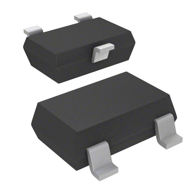
A1225, A1227, and A1229
Hall-Effect Latch for High Temperature Operation
Not for New Design
These parts are in production but have been determined to be
NOT FOR NEW DESIGN. This classification indicates that sale of
this device is currently restricted to existing customer applications.
The device should not be purchased for new design applications
because obsolescence in the near future is probable. Samples are no
longer available.
Date of status change: Septemer 3, 2018
Recommended Substitutions:
For existing customer transition, and for new customers or new applications, use APS12230.
NOTE: For detailed information on purchasing options, contact your
local Allegro field applications engineer or sales representative.
Allegro MicroSystems reserves the right to make, from time to time, revisions to the anticipated product life cycle plan for a
product to accommodate changes in production capabilities, alternative product availabilities, or market demand. The information included herein is believed to be accurate and reliable. However, Allegro MicroSystems assumes no responsibility for
its use; nor for any infringements of patents or other rights of third parties which may result from its use.
�A1225, A1227, and A1229
Hall-Effect Latch for High Temperature Operation
FEATURES AND BENEFITS
DESCRIPTION
▪ Symmetrical switchpoints
▪ Superior temperature stability
▪ Operation from unregulated supply
▪ Open-drain 25 mA output
▪ Reverse battery protection
▪ Activate with small, commercially available
permanent magnets
▪ Solid-state reliability
▪ Small size
▪ Resistant to physical stress
▪ Enhanced ESD structures result in 8 kV HBM ESD
performance without external protection components
▪ Internal protection circuits enable 40 V load dump
compliance without external protection components
These Hall-effect latches are extremely temperature-stable
and stress resistant sensor ICs especially suited for operation
over extended temperature ranges to 150°C. Superior hightemperature performance is made possible through a novel
Schmitt trigger circuit that maintains operate and release point
symmetry by compensating for temperature changes in the Hall
element. Additionally, internal compensation provides magnetic
switchpoints that become more sensitive with temperature,
hence offsetting the usual degradation of the magnetic field with
temperature. The symmetry capability makes these devices ideal
for use in pulse-counting applications where duty cycle is an
important parameter. The three basic devices (A1225, A1227,
and A1229) are identical except for magnetic switchpoints.
Each device includes on a single silicon chip a voltage regulator,
Hall-voltage generator, temperature compensation circuit,
signal amplifier, Schmitt trigger, and a buffered open-drain
output to sink up to 25 mA. The on-board regulator permits
operation with supply voltages of 3.8 to 24 V.
PACKAGES:
Not to scale
3-pin SOT23W
(suffix LH)
3-pin SIP,
matrix HD style
(suffix UA)
3-pin SIP,
chopper style
(suffix UA)
The first character of the part number suffix determines the
device operating temperature range. Suffix L is for –40°C to
150°C. Two package styles provide magnetically optimized
packages for most applications. Suffix LH is a 3-pin SOT23W
surface-mount package; suffix UA is a 3-pin ultramini SIP for
through-hole mounting. The packages are lead (Pb) free with
100% matte-tin leadframe plating.
Functional Block Diagram
Regulator
VCC
To All Subcircuits
Hall Chopping Logic
Clock / Logic
VOUT
AMP
Anti-aliasing
LP-Filter
Tuned Filter
GND
A1225-DS, Rev. 7
MCO-0000458
September 30, 2019
�A1225, A1227
and A1229
Hall-Effect Latch for High Temperature Operation
SELECTION GUIDE
Part Number
Packing [1]
Package
A1225LLHLT-T
7-in. reel, 3000 pieces/reel
3-pin SOT-23W surface mount
A1225LLHLX-T
13-in. reel, 10000 pieces/reel
3-pin SOT-23W surface mount
Bulk, 500 pieces/bag
3-pin SIP through hole
A1227LLHLT-T
7-in. reel, 3000 pieces/reel
3-pin SOT-23W surface mount
A1227LLHLX-T
13-in. reel, 10000 pieces/reel
3-pin SOT-23W surface mount
A1225LUA-T
A1227LUA-T
Bulk, 500 pieces/bag
3-pin SIP through hole
A1229LLHLT-T
7-in. reel, 3000 pieces/reel
3-pin SOT-23W surface mount
A1229LLHLX-T
13-in. reel, 10000 pieces/reel
3-pin SOT-23W surface mount
Bulk, 500 pieces/bag
3-pin SIP through hole
A1229LUA-T
[1] Contact Allegro™
Ambient
Temperature, TA
BRP(min)
(G)
BOP(max)
(G)
–40°C to 150°C
–300
300
–40°C to 150°C
–175
175
–40°C to 150°C
–200
200
for additional packaging options.
RoHS
COMPLIANT
ABSOLUTE MAXIMUM RATINGS
Rating
Unit
Forward Supply Voltage
Characteristic
Symbol
VCC
30
V
Reverse Supply Voltage
VRCC
–30
V
Output Off Voltage
VOUT
30
V
VROUT
–0.5
V
IOUT(SINK)
25
mA
–40 to 150
°C
Reverse Output Voltage
Continuous Output Current
Notes
Operating Ambient Temperature
TA
Maximum Junction Temperature
TJ(max)
165
°C
Tstg
–65 to 170
°C
Storage Temperature
Range L
Pinout Diagrams
Package LH
Package UA
3
1
2
1
2
Terminal List Table
Number
Name
Function
LH
UA
1
1
VCC
2
3
VOUT
Output signal
3
2
GND
Ground
Input power supply
3
Allegro MicroSystems
955 Perimeter Road
Manchester, NH 03103-3353 U.S.A.
www.allegromicro.com
2
�A1225, A1227
and A1229
Hall-Effect Latch for High Temperature Operation
ELECTRICAL CHARACTERISTICS: Valid at TA = –40°C to 150°C, CBYPASS = 0.1 µF, VCC = 12 V, unless otherwise noted
Characteristics
Symbol
Test Conditions
Min.
Typ. [1]
Max.
Unit [2]
24
V
ELECTRICAL CHARACTERISTICS
Supply Voltage
VCC
Supply Current
ICC
Operating; TJ ≤ 165°C
3.8
B < BRP (Output off)
–
–
6
mA
B > BOP (Output on)
–
–
6
mA
Supply Zener Voltage
VZ(sup)
ICC = 9 mA, TA = 25°C
28
–
–
V
Reverse Battery Current
IZ(sup)
VRCC = –28 V, TA = 25°C
–
–
–5
mA
–
–
12
µs
–
HIGH
–
–
–
400
–
kHz
–
175
400
mV
Power-On Time [3]
tPO
Power-On State
POS
Chopping Frequency
fchop
B < BOP
OUTPUT STAGE CHARACTERISTICS
Output Saturation Voltage
Output Leakage Current
Output Rise Time [3][4]
Output Fall
Time [3][4]
Output Zener Voltage
VOUT(sat)
IOUT = 20 mA
IOFF
VOUT = 24 V, B < BRP
–
