A1448
Low-Voltage, Full-Bridge Brushless DC Motor Driver with
Integrated Hall Sensor IC, PWM Speed Control, Soft-Switching,
and Reverse Battery and Short Circuit Protection
Discontinued Product
This device is no longer in production. The device should not be
purchased for new design applications. Samples are no longer available.
Date of status change: March 4, 2013
Recommended Substitutions:
For existing customer transition, and for new customers or new applications, contact Allegro Sales.
NOTE: For detailed information on purchasing options, contact your
local Allegro field applications engineer or sales representative.
Allegro MicroSystems, Inc. reserves the right to make, from time to time, revisions to the anticipated product life cycle plan
for a product to accommodate changes in production capabilities, alternative product availabilities, or market demand. The
information included herein is believed to be accurate and reliable. However, Allegro MicroSystems, Inc. assumes no responsibility for its use; nor for any infringements of patents or other rights of third parties which may result from its use.
�A1448
Low-Voltage, Full-Bridge Brushless DC Motor Driver with
Integrated Hall Sensor IC, PWM Speed Control, Soft-Switching,
and Reverse Battery and Short Circuit Protection
Features and Benefits
Description
▪ Low-voltage operation, 1.8 to 4.2 V
▪ Multifunction CONTROL pin input:
▫ Direct input PWM for speed control
▫ Active braking for fast stop cycle
▫ Sleep function to reduce average power consumption
▪ Reverse voltage protection on VDD and CONTROL pins
▪ Output thermal shutdown protection for robust performance
▪ Soft switching algorithm to reduce audible switching noise
and EMI
▪ Hall chopper stabilization technique for precise signal
response over operating range
▪ Antistall feature guarantees continuous rotation and
prevents overheating
▪ Single-chip solution for high reliability
▪ Miniature MLP/DFN package with industry-leading
0.40 mm maximum overall thickness
The A1448 is a full-bridge motor driver designed to drive
low-voltage, brushless DC motors. The device is designed
to allow the user to control several functions with a single
input control pin. The pin allows for direct input PWM for
speed control, is used to initiate the active braking function to reduce motor stop time, and acts as an enable pin to
engage micro-power sleep mode to reduce average power
consumption when not in use. The A1448 is designed for
use in vibration motor applications in portable devices that
require fast stop-start cycles, such as haptic applications and
vibration ring tones.
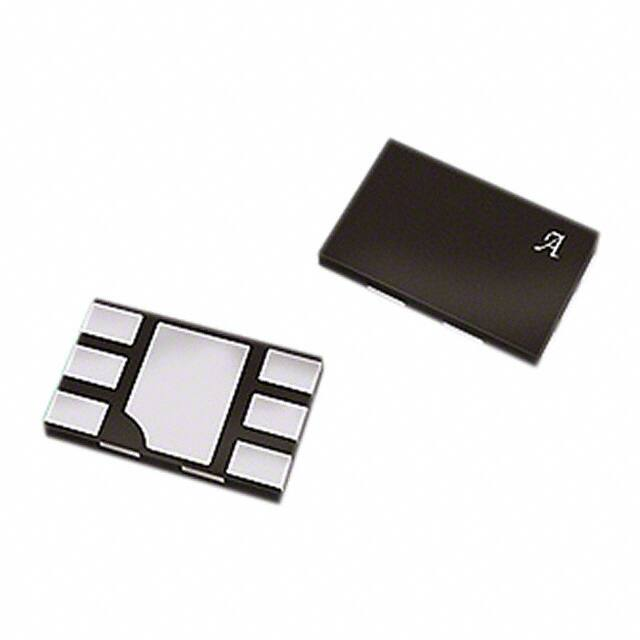
Package:
6-contact MLP/DFN
1.5 mm × 2 mm
0.40 mm maximum overall height
(EW package)
Commutation of the motor is achieved by use of a single
Hall element to detect the rotational position of an alternating-pole ring magnet. A high density CMOS semiconductor
process allows the integration of all the necessary electronics. This includes the Hall element, the motor control circuitry, and the output full bridge. Low-voltage design techniques have been employed to achieve full device functionality down to 1.8 V VDD. This fully integrated single chip
solution provides enhanced reliability (including reverse
battery protection and output short circuit protection) and
eliminates the need for any external support components.
The A1448 employs a soft-switching algorithm to reduce
audible switching noise and EMI interference. The micropower sleep mode can be initiated on the CONTROL pin,
and reduces current consumption for battery management in
Approximate size
Continued on the next page…
Functional Block Diagram
VDD
Reverse Battery
ESD
To All Subcircuits
Full Bridge
Active Braking
CONTROL
Sleep Mode
Q1
Q2
PWM Control
Drive
Logic
VOUT1
ESD
Amp
Q3
Q4
Stall Detection
Thermal Shutdown
Protection
GND
1448-DS, Rev. 4
VOUT2
�Low-Voltage, Full-Bridge Brushless DC Motor Driver with
Integrated Hall Sensor IC, PWM Speed Control, Soft-Switching,
and Reverse Battery and Short Circuit Protection
A1448
Description (continued)
portable electronic devices. This feature allows the removal of a
FET transistor for switching the device on and off.
industry with a 0.40 mm maximum thickness that allows for very
The A1448 is optimized for vibration motor applications in cellular phones, pagers, electronic toothbrushes, hand-held video
game controllers, and can also be used as a micro-fan driver for
fans motors up to 1 W.
low profile make this device ideally suited for use in applications
The Allegro DFN (EW) package is the thinnest DFN in the
thermal dissipation. Leadframe is 100% matte tin plated.
thin BLDC coin motor designs. The small package outline and
where printed circuit board area and component headroom are at
a premium. It is available in a lead (Pb) free, 6-contact MLP/DFN
micro-leadframe package, with an exposed pad for enhanced
Selection Guide
Packing1
Part Number
A1448EEWLT-P2
Package
1.5 mm × 2 mm , 0.40 mm maximum overall package
height, 6-contact MLP/DFN with exposed thermal pad
3000 pieces per 7-in. reel
1Contact Allegro for additional packing options.
2Allegro products sold in DFN package types are
not intended for automotive applications.
Absolute Maximum Ratings
Characteristic
Symbol
Notes
Rating
Units
Forward Supply Voltage
VDD
5.5
V
Reverse Supply Voltage
VRDD
–5.0
V
Forward Output Voltage
VOUT
VDD > 0 V
0 to VDD + 0.3
V
Reverse Output Voltage
VROUT
VDD > 0 V
–0.3
V
Forward CONTROL Pin Input Voltage
VIN
0 to VDD + 0.3
V
Reverse CONTROL Pin Input Voltage
VRIN
VDD – 6.0 V
V
Continuous Output Current
IOUT
±200
mA
Peak Output Current
Positive ILOAD flow is from VOUT1 to VOUT2,
TJ < TJ(max)
VINHI , TA = 25°C, no load
–
4
6
mA
Supply Current
Total Output
On-Resistance2
Reverse Battery Current
CONTROL Pin Input Threshold
CONTROL Pin Input Current
CONTROL Pin Input Frequency
CONTROL Prebraking Time3
Thermal Shutdown Limit
Thermal Shutdown Hysteresis
IDD
VIN < VINLO , TA = 25°C
–
–
10
μA
IOUT = 70 mA, VDD = 2 V, TA = 25°C
–
3.9
–
Ω
IOUT = 70 mA, VDD = 3 V, TA = 25°C
–
2.6
–
Ω
IOUT = 70 mA, VDD = 4 V, TA = 25°C
–
2.2
–
Ω
–
–
–10
mA
0.7 × VDD
–
–
V
–
–
0.2 × VDD
V
–
1.0
5
μA
fPWM
100
384
800
kHz
tPB
–
–
2.5
ms
Device is active
–
165
–
°C
TJTSD(HYS) Device is active
–
20
–
°C
RDS(on)
IRDD
VRDD = –4.2 V
VINHI
VINLO
IIN
TJTSD
VIN = 3.0 V
Magnetic Characteristics4
Magnetic Switchpoints
BOP
–
35
75
G
BRP
–75
–35
–
G
BHYS
VOUT1
Output Polarity
VOUT2
–
70
–
G
B < BRP
–
LOW
–
V
B > BOP
–
HIGH
–
V
B < BRP
–
HIGH
–
V
B > BOP
–
LOW
–
V
1Extended
VDD range affects RDS(on) and Bx.
2Total Output On-Resistance = R
DS(on)Q1 + RDS(on)Q4 , or RDS(on)Q2 + RDS(on)Q3 , where Qx refers to the internal full-bridge transistors.
3Device initiates braking algorithm if the CONTROL pin is pulled to GND for longer than the maximum specified CONTROL Prebraking Time.
41 G (gauss) = 0.1 mT (millitesla).
Allegro MicroSystems, Inc.
115 Northeast Cutoff
Worcester, Massachusetts 01615-0036 U.S.A.
1.508.853.5000; www.allegromicro.com
3
�A1448
Low-Voltage, Full-Bridge Brushless DC Motor Driver with
Integrated Hall Sensor IC, PWM Speed Control, Soft-Switching,
and Reverse Battery and Short Circuit Protection
Functional Description
Soft Switching
The A1448 device includes a soft-switching algorithm that
controls the output switching slew rate for both output pins. As a
result, the A1448 device is ideal for use in applications requiring
low audible switching noise and low EMI. The resistance of the
output transistors is controlled to ensure the smooth switching of
the outputs, as illustrated in figure 1.
CONTROL Pin Functionality: PWM, Braking, and Sleep
Mode Input
The CONTROL input pin accepts an external signal that can
control the speed of the output bridge, initiate active braking,
and put the device into sleep mode. Signals higher than the VINHI
threshold will turn on the output bridge according to the applied
magnetic field. Applying a PWM signal to the CONTROL pin
will turn the bridge on and off according to the PWM duty cycle.
When the CONTROL pin is pulled to GND, the device initiates
its internal active braking algorithm to stop the motor. After
braking, the device enters micro-power sleep mode. The device
becomes active again when the CONTROL pin is pulled higher
than VINHI.
Antistall Algorithm
If a stall condition occurs, the device will execute an antistall
algorithm to re-start the motor.
VOUT2
VOUT1
tSW
Figure 1. A1448 output soft switching with a 30 Ω resistive load
Allegro MicroSystems, Inc.
115 Northeast Cutoff
Worcester, Massachusetts 01615-0036 U.S.A.
1.508.853.5000; www.allegromicro.com
4
�A1448
Low-Voltage, Full-Bridge Brushless DC Motor Driver with
Integrated Hall Sensor IC, PWM Speed Control, Soft-Switching,
and Reverse Battery and Short Circuit Protection
Application Information
Figure 2 shows a typical vibration motor application in which
speed control, active braking, and sleep mode are required on the
CONTROL pin.
Note that:
Figure 3 shows an application circuit in which 100% duty cycle
is required. Tying the CONTROL pin to VDD disables the braking
function and the sleep mode. The user must control supply in
order to control the speed of the motor. This represents a 2-wire
motor design.
• Thermal shutdown also is integrated, to protect the device
against inadvertent output shorts during manufacturing or
testing.
• No external diode is required for reverse battery protection
because the protection is fully integrated into the IC.
• A bypass capacitor of 0.1 μF is required. This capacitor is usually included on the end user PCB and therefore not necessary
on the motor PCB.
VBATT
+
VOUT2
VDD
System Logic
Control
CBYP
A1448
CONTROL
I/O
M
VOUT1
GND
NC
Figure 2. Three-wire vibration motor application circuit
VBATT
+
VDD
VOUT2
A1448
CBYP
CONTROL
NC
M
VOUT1
GND
Figure 3. Two-wire vibration motor application circuit
Allegro MicroSystems, Inc.
115 Northeast Cutoff
Worcester, Massachusetts 01615-0036 U.S.A.
1.508.853.5000; www.allegromicro.com
5
�Low-Voltage, Full-Bridge Brushless DC Motor Driver with
Integrated Hall Sensor IC, PWM Speed Control, Soft-Switching,
and Reverse Battery and Short Circuit Protection
A1448
Power Derating
The device must be operated below the maximum junction temperature of the device, TJ (max). Under certain combinations of
peak conditions, reliable operation may require derating supplied
power or improving the heat dissipation properties of the application. This section presents a procedure for correlating factors
affecting operating TJ. (Thermal data is also available on the
Allegro MicroSystems website.)
For a load of 30 Ω, and given common conditions such as:
TA= 25°C, VDD = 3 V, IDD = 83 mA, VLOAD = 2.43 V,
ILOAD = 81 mA, and RθJA = 125 °C/W, (see figure 5)
then:
PD = VDD × IDD – VLOAD × ILOAD
The package thermal resistance, RθJA, is a figure of merit summarizing the ability of the application and the device to dissipate
heat from the junction (die), through all paths to the ambient air.
Its primary component is the effective thermal conductivity, K, of
the printed circuit board, including adjacent devices and traces.
Radiation from the die through the device case, RθJC, is relatively
small component of RθJA. Ambient air temperature, TA, and air
motion are significant external factors, damped by overmolding.
= 3 V × 83 mA – 2.43 V × 81 mA
= 52.17 mW
ΔT = PD × RθJA
= 52.17 mW × 125 °C/W
= 7°C
The effect of varying power levels (Power Dissipation, PD), can
be estimated. The following formulas represent the fundamental
relationships used to estimate TJ, at various PD levels.
PD = VIN × IIN
(1)
ΔT = PD × RθJA
(2)
TJ = TA + ΔT
(3)
TJ = TA + ΔT
= 25°C + 7°C
= 32°C
A worst-case estimate, PD(max), represents the maximum allowable power level, without exceeding TJ(max), at a selected RθJA
and TA.
VBATT
+
VDD
VOUT2
A1448
CBYP
CONTROL
NC
M
VOUT1
GND
Figure 5. A1448 typical application
Allegro MicroSystems, Inc.
115 Northeast Cutoff
Worcester, Massachusetts 01615-0036 U.S.A.
1.508.853.5000; www.allegromicro.com
6
�Low-Voltage, Full-Bridge Brushless DC Motor Driver with
Integrated Hall Sensor IC, PWM Speed Control, Soft-Switching,
and Reverse Battery and Short Circuit Protection
A1448
Package EW, 6-Pin MLP/DFN
1.50 ±0.15
0.94 F
E
6
F
0.50
0.30
6
0.99 F
2.00 ±0.15
0.70
1.575
A
1
1
0.325
1.10
7X
D
SEATING
PLANE
0.08 C
C
C
PCB Layout Reference View
0.38 ±0.02
0.50 BSC
B
+0.055
0.325 –0.045
0.70 ±0.10
NN
YWW
0.25 ±0.05
1
1
1.25 ±0.05
G
Standard Branding Reference View
N = Last two digits of device part number
Y = Last digit of year of manufacture
W = Week of manufacture
6
1.10 ±0.10
For Reference Only, not for tooling use (refernce DWG-2856; similar to
JEDEC Type 1, MO-229X2BCD)
Dimensions in millimeters
Exact case and lead configuration at supplier discretion within limits shown
A Terminal #1 mark area
B Exposed thermal pad (reference only, terminal #1
identifier appearance at supplier discretion)
C Reference land pattern layout (reference IPC7351
SON50P200X200X100-9M);
All pads a minimum of 0.20 mm from all adjacent pads; adjust as
necessary to meet application process requirements and PCB layout
tolerances; when mounting on a multilayer PCB, thermal vias at the
exposed thermal pad land can improve thermal dissipation (reference
EIA/JEDEC Standard JESD51-5)
D Coplanarity includes exposed thermal pad and terminals
E Active Area Depth 0.15 mm REF
F Hall Element (not to scale)
G Branding scale and appearance at supplier discretion
Allegro MicroSystems, Inc.
115 Northeast Cutoff
Worcester, Massachusetts 01615-0036 U.S.A.
1.508.853.5000; www.allegromicro.com
7
�Low-Voltage, Full-Bridge Brushless DC Motor Driver with
Integrated Hall Sensor IC, PWM Speed Control, Soft-Switching,
and Reverse Battery and Short Circuit Protection
A1448
Revision History
Revision
Revision Date
Rev. 4
October 26, 2011
Description of Revision
Update Selection Guide
Copyright ©2008-2011, Allegro MicroSystems, Inc.
Allegro MicroSystems, Inc. reserves the right to make, from time to time, such departures from the detail specifications as may be required to permit improvements in the performance, reliability, or manufacturability of its products. Before placing an order, the user is cautioned to verify that the
information being relied upon is current.
Allegro’s products are not to be used in life support devices or systems, if a failure of an Allegro product can reasonably be expected to cause the
failure of that life support device or system, or to affect the safety or effectiveness of that device or system.
The information included herein is believed to be accurate and reliable. However, Allegro MicroSystems, Inc. assumes no responsibility for its use;
nor for any infringement of patents or other rights of third parties which may result from its use.
For the latest version of this document, visit our website:
www.allegromicro.com
Allegro MicroSystems, Inc.
115 Northeast Cutoff
Worcester, Massachusetts 01615-0036 U.S.A.
1.508.853.5000; www.allegromicro.com
8
�