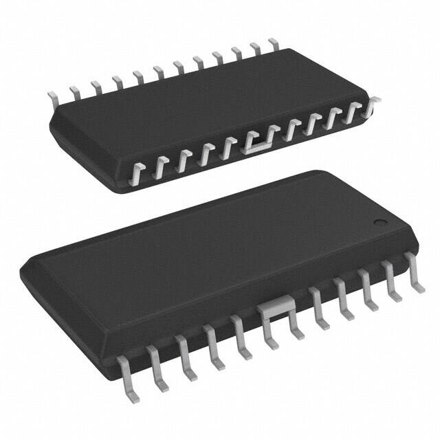
2919 DUAL FULL-BRIDGE MOTOR DRIVER
2919
The A2919SB and A2919SLB motor drivers are designed to drive both windings of a bipolar stepper motor or bidirectionally control two dc motors. Both bridges are capable of sustaining 45 V and include internal pulse-width modulation (PWM) control of the output current to 750 mA. The outputs have been optimized for a low output-saturation voltage drop (less than 1.8 V total source plus sink at 500 mA). For PWM current control, the maximum output current is determined by the user’s selection of a reference voltage and sensing resistor. Two logic-level inputs select output current limits of 0%, 41%, 67%, or 100% of the maximum level. A PHASE input to each bridge determines load current direction. The bridges include both ground clamp and flyback diodes for protection against inductive transients. Internally generated delays prevent cross-over currents when switching current direction. Special power-up sequencing is not required. Thermal protection circuitry disables the outputs if the chip temperature exceeds safe operating limits. The A2919SB is supplied in a 24-pin dual in-line plastic batwing package with a copper lead-frame and heat sinkable tabs for improved power dissipation capabilities. The A2919SLB is supplied in a 24-lead surface-mountable SOIC. Their batwing construction provides for maximum package power dissipation in the smallest possible construction. The A2919SB/SLB are available for operation from -40°C to +85°C. To order, change the suffix from 'S–' to 'E–'. These devices are also available on special order for operation to +125°C. For applications not requiring quarter-step operation, but desire lower detent or running current, the similar UDN2916B/EB/LB may be preferred.
DUAL FULL-BRIDGE PWM MOTOR DRIVER
A2919SB
OUT 1A OUT 2A E2 SENSE 2 OUT 2B GROUND GROUND I 02 I
12
Data Sheet 29319.21
1 2 3 4 5 6 7 8 2
VBB
24 23
LOAD SUPPLY E1 SENSE 1 OUT 1B I 01 GROUND GROUND I 11 PHASE 1 V REF 1 RC 1 LOGIC SUPPLY
1
22 21 20 19 18 17
PWM 1
9 9 10 11 12 θ2
θ1
16 15 14
PHASE 2 V REF 2 RC 2
PWM 2
V CC
13
Dwg. PP-005
ABSOLUTE MAXIMUM RATINGS at TJ ≤ 150°C
Motor Supply Voltage, VBB ................... 45 V Output Current, IOUT (Peak, tw ≤ 20 µs) ........................ ±1.0 A (Continuous) .......................... ±750 mA Logic Supply Voltage, VCC ................... 7.0 V Logic Input Voltage Range, VIN ............................... - 0.3 V to +7.0 V Output Emitter Voltage, VE .................. 1.5 V Package Power Dissipation, PD ....................................... See Graph Operating Temperature Range, TA ................................. -20°C to +85°C Storage Temperature Range, TS ............................... - 55°C to +150°C
Output current rating may be limited by duty cycle, ambient temperature, and heat sinking. Under any set of conditions, do not exceed the specified peak current rating or a junction temperature of +150°C.
FEATURES
s s s s s s s 750 mA Continuous Output Current 45 V Output Sustaining Voltage Internal Clamp Diodes Internal PWM Current Control Low Output Saturation Voltage Internal Thermal Shutdown Circuitry Half- or Quarter-Step Operation of Bipolar Stepper Motors RθJT 6.0°C/W 6.0°C/W
Always order by complete part number: Part Number Package RθJA A2919SB 24-Pin DIP 40 °C/W A2919SLB 24-Lead SOIC 55 °C/W
�2919 DUAL FULL-BRIDGE MOTOR DRIVER
A2919SLB
ALLOWABLE PACKAGE POWER DISSIPATION IN WATTS
5
RθJT = 6.0°C/W
I
02
1
PWM 2
24 23 22 2 21 20 19
VBB
LOAD SUPPLY OUT 2B SENSE 2 E2 OUT 2A GROUND GROUND OUT 1A E1 SENSE 1 OUT 1B
I 12 PHASE 2 V REF 2 RC 2 GROUND GROUND LOGIC SUPPLY RC 1 V REF 1 PHASE 1 I 11
2 3 4 5 6 7 8 9 9 V CC θ2
4
3
SUFFIX 'B', R θJA = 40°C/W
2
18 17 16 1 15
1
SUFFIX 'LB', R θJA = 55°C/W
0 25 50 75 100 TEMPERATURE IN °C 125 150
Dwg. GP-049A
10
PWM 1
11 12
θ1
14 13
TRUTH TABLE
I 01
PHASE
Dwg. PP-047
OUTA H L
OUTB L H
H L
PWM CURRENT-CONTROL CIRCUITRY
'B' PACKAGE, CHANNEL 1 PIN NUMBERS SHOWN. V
BB
24
OUT B
1 21
OUT A V REF 15 60 kΩ ÷10 120 kΩ I 0 20 I 1 17 42 kΩ RS
23 E
SENSE –
22
+
ONE SHOT
14 RC
SOURCE DISABLE
RC CC RT
CT
Dwg. EP-007-3
115 Northeast Cutoff, Box 15036 Worcester, Massachusetts 01615-0036 (508) 853-5000 W Copyright © 1994 Allegro MicroSystems, Inc.
�2919 DUAL FULL-BRIDGE MOTOR DRIVER
ELECTRICAL CHARACTERISTICS at TA = +25°C, TJ ≤ 150°C, VBB = 45 V, VCC = 4.75 V to 5.25 V, VREF = 5.0 V (unless otherwise noted).
Limits Characteristic Output Drivers (OUTA or OUT B)
Motor Supply Range Output Leakage Current VBB ICEX Operating VOUT = V BB VOUT = 0 Output Sustaining Voltage Output Saturation Voltage VCE(sus) VCE(SAT) IOUT = ± 750 mA, L = 3.0 mH Sink Driver, IOUT = +500 mA Sink Driver, IOUT = +750 mA Source Driver, IOUT = -500 mA Source Driver, IOUT = -750 mA Clamp Diode Leakage Current Clamp Diode Forward Voltage Driver Supply Current IR VF IBB(ON) IBB(OFF) VR = 45 V IF = 750 mA Both Bridges ON, No Load Both Bridges OFF 10 — — 45 + VF — — — — — — — — — < 1.0
很抱歉,暂时无法提供与“A2919SLB”相匹配的价格&库存,您可以联系我们找货
免费人工找货