3422
HALL-EFFECT, DIRECTION-DETECTION SENSORS
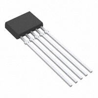
The A3422xKA Hall-effect, direction-detection sensor is a new generation of special-function integrated sensors that is capable of sensing the direction of rotation of a ring magnet. This transducer provides separate digital outputs that provide information on magnet rotation speed, direction, and magnet pole count. This device eliminates the major manufacturing hurdles encountered in fine-pitch direction-detection applications, namely maintaining accurate mechanical location between the two active Hall elements. Here, the two Hall elements are photolithographically aligned to better than 1 μm, as contrasted with 100 μm or worse mechanical location tolerance when manufactured discretely. This highly sensitive, temperature-stable, magnetic transducer is ideal for use in digital-encoder systems in the harsh environments of automotive or industrial applications. The A3422xKA is a high-sensitivity device optimized for use with high-density magnets. The A3422xKA monolithic integrated circuit contains two independent Hall-effect bipolar switches whose digital outputs are internally coupled to CMOS logic circuitry that decodes signal speed and direction. Extremely low-drift BiCMOS circuitry is used for the amplifiers to ensure symmetry between the two switches so that signal quadrature can be maintained. An on-chip voltage regulator allows the use of this device from a 4.5 V to 18 V supply. The outputs are standard open-collector outputs. Two operating temperature ranges are provided; suffix ‘E–’ is for the automotive and industrial temperature range of -40°C to +85°C, suffix ‘L–’ is for the automotive and military temperature range of -40°C to +150°C. The 5-pin ‘KA’ SIP package provides a cost-competitive solution to magnetic sensing in harsh environments.
Data Sheet 27650.1B
E1
E2
X
X
LOGIC
VCC
1
2
3
4
5
DIRECTION
GROUND
E1 OUTPUT
SUPPLY
Dwg PH-015
Pinning is shown viewed from branded side.
SPEED
ABSOLUTE MAXIMUM RATINGS
Supply Voltage, VCC . . . . . . . . . . . . . . 18 V Magnetic Flux Density, B . . . . Unlimited Output OFF Voltage, VOUT . . . . . . . . . VCC Output Sink Current, IOUT . . . . . . . 30 mA Package Power Dissipation, PD . . . . . . . . . . . . . . . . . . . . . 500 mW Operating Temperature Range, TA Suffix ‘E–’ . . . . . . . . . -40°C to +85°C Suffix ‘L–’ . . . . . . . . -40°C to +150°C Storage Temperature Range, TS . . . . . . . . . . . . . . -65°C to +170°C
FEATURES
• • • •
Internal Direction-Decoding Circuitry Two Matched Hall Bipolar Switches on a Single Substrate Superior Temperature Stability 4.5 V to 18 V Operation Electrically Defined Power-On State Undervoltage Lockout
�3422 HALL-EFFECT, DIRECTION-DETECTION SENSOR
Selection Guide
Part Number A3422EKA-T A3422LKA-T
1Pb-based
Pb-Free1 Yes Yes
Packing2 Bulk, 500 pieces/bag Bulk, 500 pieces/bag
Mounting 5-pin SIP through hole 5-pin SIP through hole
Ambient, TA (°C) –40 to 85 –40 to 150
variants are being phased out of the product line. The variants cited in this footnote are in production but have been determined to be NOT FOR NEW DESIGN. This classification indicates that sale of this device is currently restricted to existing customer applications. The variants should not be purchased for new design applications because obsolescence in the near future is probable. Samples are no longer available. Status change: May 1, 2006. These variants include: A3422EKA and A3422LKA. 2Contact Allegro for additional packing options.
FUNCTIONAL BLOCK DIAGRAM
1 SUPPLY 2 DIRECTION
UVLO
REG
LOGIC
POWER-ON LOGIC
3
GROUND
4
E1 OUTPUT
E2
X
E1
X
5
SPEED
Dwg. FH-018
TIMING DIAGRAM
CHANGE IN DIRECTION
td DIRECTION
Dwg. WH-012A
+B 0
BOP1 BRP1
-B +B 0 BRP2 -B BOP2
OUT E1
OUT E2 (INTERNAL)
SPEED (OUT E1 XOR OUT E2)
2
115 Northeast Cutoff, Box 15036 Worcester, Massachusetts 01615-0036 (508) 853-5000 Copyright © 2001, 2003 Allegro MicroSystems, Inc.
�3422 HALL-EFFECT, DIRECTION-DETECTION SENSOR
ELECTRICAL CHARACTERISTICS over operating temperature range.
Limits Characteristic Supply Voltage Range Output Leakage Current Output Saturation Voltage Power-On State Undervoltage Lockout Undervoltage Hysteresis Power-On Time Output Rise Time Output Fall Time Direction Change Delay Supply Current Symbol VCC IOFF VOUT(SAT) POS VCC(UV) VCC(hys) tpo tr tf td ICC Test Conditions Operating, TJ < 165°C1 VOUT = VCC = 18 V IOUT = 20 mA VCC = 0 → 5 V, BRP1 < B < BOP1, BRP2 < B < BOP2 IOUT = 20 mA, VCC = 0 → 5 V Lockout (VCC(UV)) - Shutdown VCC > 4.5 V CL = 20 pF, RL = 820 Ω CL = 20 pF, RL = 820 Ω CL = 20 pF, RL = 820 Ω VCC = 8 V, All outputs OFF Min. 4.5 — — OFF — — — — — 0.5 5.0 Typ. —
很抱歉,暂时无法提供与“A3422EKA-T”相匹配的价格&库存,您可以联系我们找货
免费人工找货