A3966SLB

A3966SLB

  • 厂商:

    ALLEGRO(埃戈罗)

  • 封装:

    SOIC16

  • 描述:

    IC MTRDRV BIPLR 4.75-5.5V 16SOIC

  • 详情介绍
  • 数据手册
  • 价格&库存
A3966SLB 数据手册
Data Sheet 29319.25A† 3966 A3966SLB OUT1A PHASE 1 ENABLE 1 GROUND SENSE1 OUT 1B LOAD SUPPLY REFERENCE 1 V 2 3 4 5 6 7 8 V V BB VCC RC LOGIC LOGIC BB DUAL FULL-BRIDGE PWM MOTOR DRIVER The A3966SA and A3966SLB are designed to drive both windings of a two-phase bipolar stepper motor. Each device includes two H-bridges capable of continuous output currents of ±650 mA and operating voltages to 30 V. Motor winding current can be controlled by the internal fixed-frequency, pulse-width modulated (PWM), current-control circuitry. The peak load current limit is set by the user’s selection of a reference voltage and current-sensing resistors. Except for package style and pinout, the two devices are identical. The fixed-frequency pulse duration is set by a user-selected external RC timing network. The capacitor in the RC timing network also determines a user-selectable blanking window that prevents false triggering of the PWM current-control circuitry during switching transitions. To reduce on-chip power dissipation, the H-bridge power outputs have been optimized for low saturation voltages. The sink drivers feature Allegro’s patented Satlington™ output structure. The Satlington outputs combine the low voltage drop of a saturated transistor and the high peak current capability of a Darlington. For each bridge, a PHASE input controls load-current polarity by selecting the appropriate source and sink driver pair. For each bridge, an ENABLE input, when held high, disables the output drivers. Special powerup sequencing is not required. Internal circuit protection includes thermal shutdown with hysteresis, ground-clamp and flyback diodes, and crossovercurrent protection. The A3966SA is supplied in a 16-pin dual in-line plastic package. The A3966SLB is supplied in a 16-lead plastic SOIC with copper heat sink tabs. The power tab is at ground potential and needs no electrical isolation. 16 15 14 13 12 11 10 9 OUT 2A PHASE 2 ENABLE 2 GROUND SENSE 2 OUT 2B LOGIC SUPPLY RC REF Dwg. PP-066-1 ABSOLUTE MAXIMUM RATINGS Load Supply Voltage, VBB ...................... 30 V Output Current, IOUT (peak) ........... ±750 mA (continuous) .............................. ±650 mA Logic Supply Voltage, VCC .................... 7.0 V Input Voltage, Vin ........ -0.3 V to VCC + 0.3 V Sense Voltage, VS ................................ 1.0 V Package Power Dissipation (TA = 25°C), PD A3966SA ..................................... 2.08 W* A3966SLB ................................... 1.87 W* Operating Temperature Range, TA ..................................... -20°C to +85°C Junction Temperature, TJ .................................................. +150°C Storage Temperature Range, TS ................................... -55°C to +150°C Output current rating may be limited by duty cycle, ambient temperature, and heat sinking. Under any set of conditions, do not exceed the specified current rating or a junction temperature of 150°C. * Per SEMI G42-88 Specification, Thermal Test Board Standardization for Measuring Junction-to-Ambient Thermal Resistance of Semiconductor Packages. FEATURES I I I I I I I I ±650 mA Continuous Output Current 30 V Output Voltage Rating Internal Fixed-Frequency PWM Current Control Satlington™ Sink Drivers User-Selectable Blanking Window Internal Ground-Clamp & Flyback Diodes Internal Thermal-Shutdown Circuitry Crossover-Current Protection and UVLO Protection Always order by complete part number: Part Number A3966SA A3966SLB Package 16-pin DIP 16-lead batwing SOIC RθJA 60°C/W 67°C/W RθJC 38°C/W — RθJT — 6°C/W 3966 DUAL FULL-BRIDGE PWM MOTOR DRIVER FUNCTIONAL BLOCK DIAGRAM OUT 1A OUT 1B V CC PHASE 1 V BB PHASE 2 + LOGIC SUPPLY OUT 2A OUT 2B LOAD SUPPLY UVLO & TSD CONTROL LOGIC1 CONTROL LOGIC2 UVLO & TSD ENABLE 1 SOURCE ENABLE 1 ENABLE 2 CURRENT-SENSE COMPARATOR 1 SENSE 1 SENSE 2 CURRENT-SENSE COMPARATOR 2 PWM LATCH 1 R Q S BLANKING GATE 1 + – + – BLANKING GATE 2 PWM LATCH 2 R Q S ÷4 OSC RC R1S R 2S SOURCE ENABLE 2 GROUND RT CT REFERENCE Dwg. FP-036-6 A3966SA SENSE 1 OUT 1B LOAD SUPPLY REFERENCE RC LOGIC SUPPLY OUT 2B SENSE 2 1 LOGIC TRUTH TABLE 16 15 14 ENABLE 1 PHASE 1 OUT 1A GROUND GROUND OUT 2A PHASE 2 ENABLE 2 2 3 4 5 6 7 8 V REF RC V PHASE X H L ENABLE H L L OUTA Off H L OUTB Off L H V BB 13 12 11 X = Irrelevant CC LOGIC 10 9 Dwg. PP-066-2 2 115 Northeast Cutoff, Box 15036 Worcester, Massachusetts 01615-0036 (508) 853-5000 Copyright © 1998, 2000 Allegro MicroSystems, Inc. 3966 DUAL FULL-BRIDGE PWM MOTOR DRIVER ELECTRICAL CHARACTERISTICS at TA = +25°C, VBB = 30 V, VCC = 4.75 V to 5.5 V, VREF = 2 V, VS = 0 V, 56 kΩ & 680 pF RC to Ground (unless noted otherwise) Limits Characteristic Output Drivers Load Supply Voltage Range Output Leakage Current VBB ICEX Operating, IOUT = ±650 mA, L = 3 mH VOUT = 30 V VOUT = 0 V Output Saturation Voltage VCE(SAT) Source Driver, IOUT = -400 mA Source Driver, IOUT = -650 mA Sink Driver, IOUT = +400 mA, VS = 0.5 V Sink Driver, IOUT = +650 mA, VS = 0.5 V Clamp Diode Forward Voltage VF IF = 400 mA IF = 650 mA Motor Supply Current (No Load) IBB(ON) IBB(OFF) VENABLE1 = VENABLE2 = 0.8 V VENABLE1 = VENABLE2 = 2.4 V VCC — — — — — — — — — — —
A3966SLB
物料型号: - A3966SA:16-pin DIP封装 - 
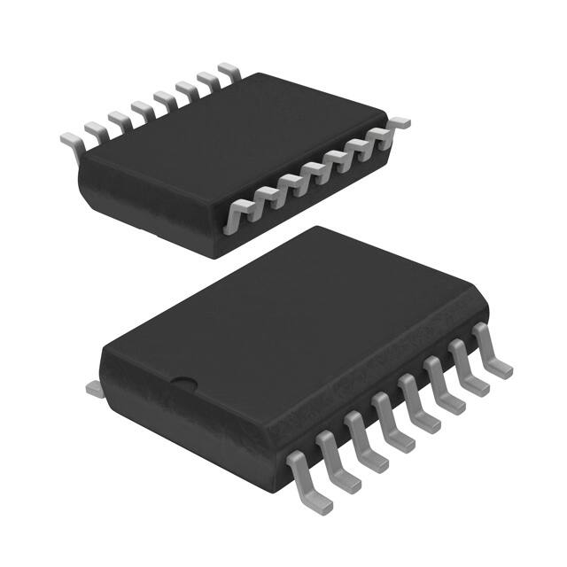
A3966SLB:16-lead batwing SOIC封装

器件简介: A3966SA和A3966SLB是双H桥全桥PWM电机驱动器,设计用于驱动两相双极步进电机的两个绕组。

每个设备包含两个H桥,能够持续输出±650 mA的电流,工作电压可达30V。

电机绕组电流可通过内部固定频率、脉宽调制(PWM)电流控制电路进行控制。


引脚分配: - A3966SA:16-pin双列直插式封装。

- A3966SLB:16-lead SOIC封装,带铜热沉片。


参数特性: - 连续输出电流:±650 mA - 输出电压额定值:30V - 内部固定频率PWM电流控制 - Satlington™沉驱动器 - 用户可选的空白窗口 - 内部接地钳位和反飞保护 - 内部热关机电路 - 交叉电流保护和欠压保护

功能详解: 内部PWM电流控制:通过内部固定频率PWM控制电路控制每个电机绕组的负载电流。

电流控制比较器通过外部感测电阻(Rs)检测负载电流,负载电流持续增加直到达到预定值。

电流感测比较器空白:为防止电流尖峰错误地重置源使能锁存器,当源驱动器开启时,电流控制比较器输出会被短暂空白。

负载电流调节:由于内部逻辑和开关延迟,实际负载电流峰值会略高于I_TRIP值。


应用信息: 适用于需要双极步进电机精确电流控制的应用场合。


封装信息: - A3966SA:16-pin DIP封装,热阻RBJA为60°C/W,RBJT为空。

- A3966SLB:16-lead SOIC封装,热阻RBJA为67°C/W,ReJc为空,RBJT为6°C/W。
A3966SLB 价格&库存

很抱歉,暂时无法提供与“A3966SLB”相匹配的价格&库存,您可以联系我们找货

免费人工找货