ARG81400
Multi-Output Regulator with Buck or Buck/Boost Pre-Regulator,
Synchronous Buck, 5x LDO Outputs, Watchdog, and SPI
2
-
FEATURES AND BENEFITS
• A2-SIL™ compliant—device features for safety-critical
systems
• Automotive AEC-Q100 qualified
• Wide input voltage range, 3.8 to 40 VIN operating range,
50 VIN maximum
• Buck or buck/boost pre-regulator (VREG)
• Adjustable 1.25 to 3.3 V synchronous buck
• Frequency dithering and controlled slew rate helps
reduce EMI/EMC
• Four internal linear regulators with foldback short-circuit
protection, 3.3 V (3V3) and three 5 V (V5CAN, V5A,
and V5B)
• One internal 5 V linear regulator (V5P) with foldback
short-circuit and short-to-supply protection
• Power-on reset signal indicating a fault on the synchronous
buck, 3V3 or V5A regulator outputs (NPOR)
• Window watchdog timer with fail-safe features
• Dual bandgaps for increased safety coverage and fault
detection, BGVREF, BGFAULT
• Control and diagnostic reporting through a serial
peripheral interface (SPI)
• Logic enable input (ENB) for microprocessor control
• Ignition enable input (ENBAT) with status indicator output
• OV and UV protection for all output rails
• Pin-to-pin and pin-to-ground tolerant at every pin
APPLICATIONS
Provides system power (for microcontroller/DSP, CAN,
sensors, etc.) in:
• Industrial applications
• Electronic power steering (EPS)
• Advanced braking systems (ABS)
• Transmission control units (TCU)
• Emissions control modules
• Other automotive applications
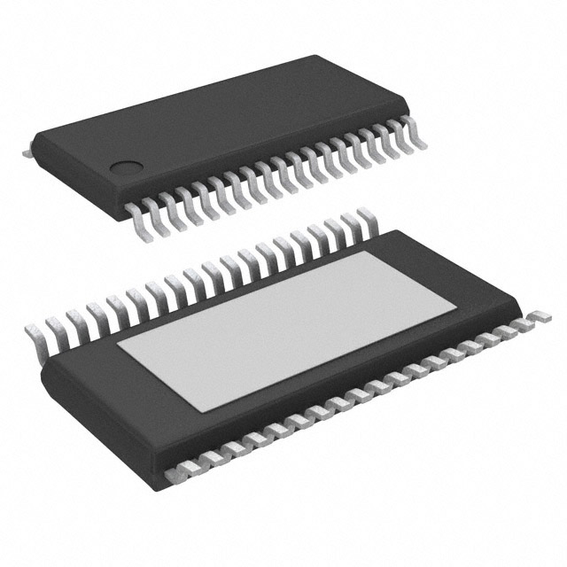
PACKAGE
38-Pin eTSSOP
(suffix LV)
Not to scale
Enable and
Startup Timing
Dual
Bandgaps
Charge
Pump
Thermal
Shutdown
(TSD)
5.35 V
(VREG)
Buck-Boost
Pre-Regulator
Serial
Interface
(SPI)
DESCRIPTION
The ARG81400 is rated up to 50 V input and provides six
total outputs. There are five LDOs and a post regulated DC/
DC switcher to power MCUs, as well as a watchdog and SPI.
Designed for high-temperature operation, the ARG81400 is
ideal for automotive and industrial applications.
The device uses a buck or buck/boost pre-regulator to efficiently
feed five linear regulators— 3.3 V / 90 mA, 5 V / 200 mA,
5 V / 30 mA, 5 V / 55 mA, and 5 V /100 mA (short-to-supply
protected)—and an adjustable output, 600 mA synchronous buck.
Enable inputs to the ARG81400 include a logic level (ENB)
and a high-voltage (ENBAT). The ARG81400 also provides
flexibility with disable function of the individual 5 V rails
through a serial peripheral interface (SPI).
Diagnostic outputs from the ARG81400 include a power-onreset output (NPOR), an ENBAT status output, and a fault flag
output to alert the microprocessor that a fault has occurred.
The microprocessor can read fault status through SPI. Dual
bandgaps, one for regulation and one for fault checking, improve
safety coverage and fault detection.
The ARG81400 contains a Window Watchdog timer with a
programmable detect period of 250, 500, 1000, or 2000 μs. The
watchdog timer enters an active state after NPOR transitions
high and the processor has exercised the WD Test routine. The
watchdog can be put into flash mode or be reset via secure
SPI commands.
Protection features include undervoltage and overvoltage on
all output rails. In case of a shorted output, all linear regulators
feature foldback overcurrent protection. In addition, the V5P
output is protected from a short-to-supply event. Both switching
regulators include pulse-by-pulse current limit, hiccup mode
short-circuit protection, LX short-circuit protection, missing
asynchronous diode protection (VREG only), and thermal
shutdown.
The ARG81400 is supplied in a low-profile (1.2 mm maximum
height) 38-lead eTSSOP package (suffix “LV”) with exposed
power pad.
Adjustable
1.25 to 3.3 V
Sync. Buck
Regulator
OV/UV Detect
with BIST and
NPOR
3.3 V Linear
Regulator with
Foldback
Protection
Clock Edge
Window
Watchdog
5 V Linear
Regulator with
Foldback
Protection
5 V Linear
Regulator with
Foldback
Protection
5 V Linear
Regulator with
Foldback
Protection
5 V Protected Linear
Regulator with Foldback
and Short-to-VBAT Protection
ARG81400 Simplified Block Diagram
ARG81400-DS, Rev. 6
MCO-0000213
June 10, 2020
�Multi-Output Regulator with Buck or Buck/Boost Pre-Regulator,
Synchronous Buck, 5x LDO Outputs, Watchdog, and SPI
ARG81400
SELECTION GUIDE
[1]
Part Number
Temperature Range
Package
Packing [1]
Lead Frame
ARG81400KLVATR
–40 to 150°C
38-pin eTSSOP w/ thermal pad
4000 pieces per 7-in reel
100% matte tin
Contact Allegro for additional packing options.
SPECIFICATIONS
ABSOLUTE MAXIMUM RATINGS [2]
Characteristic
Symbol
VIN
Notes
VVIN
VENBAT
ENBAT
With current limiting resistor [3]
IENBAT
LX1
VLX1
V5P
VV5P
Unit
−0.3 to 50
V
−13 to 50
V
−0.3 to 8
V
±75
mA
−0.3 to VVIN + 0.3
V
t < 250 ns
−1.5
V
t < 50 ns
VVIN + 3 V
V
−0.3 to 60
V
−1 to 50
V
VVCP, VCP1,
VCP2
VCP, CP1, CP2
Rating
Independent of VVIN
All other pins
−0.3 to 7
V
Junction Temperature
TJ
−40 to 165
°C
Storage Temperature Range
Tstg
−40 to 150
°C
Stresses beyond those listed in this table may cause permanent damage to the device. The absolute maximum ratings are stress ratings only, and functional operation of
the device at these or any other conditions beyond those indicated in the Electrical Characteristics table is not implied. Exposure to absolute-maximum-rated conditions
for extended periods may affect device reliability.
[3] The higher ENBAT ratings (–13 V and 50 V) are measured at node “A” in the following circuit configuration:
[2]
Node “A”
≥450 Ω
ENBAT
VENBAT
+
-
ARG81400
GND
THERMAL CHARACTERISTICS: May require derating at maximum conditions; see application information
Characteristic
Junction to Ambient Thermal Resistance
[4] Additional
Symbol
RθJA
Test Conditions [4]
Value
Unit
30
°C/W
eTSSOP-38 (LV) package
thermal information available on the Allegro website.
Allegro MicroSystems
955 Perimeter Road
Manchester, NH 03103-3353 U.S.A.
www.allegromicro.com
2
�ARG81400
Multi-Output Regulator with Buck or Buck/Boost Pre-Regulator,
Synchronous Buck, 5x LDO Outputs, Watchdog, and SPI
Table of Contents
Features and Benefits............................................................ 1
Description........................................................................... 1
Applications.......................................................................... 1
Package.............................................................................. 1
Simplified Block Diagram....................................................... 1
Selection Guide.................................................................... 2
Specifications....................................................................... 2
Absolute Maximum Ratings................................................. 2
Thermal Characteristics...................................................... 2
Functional Block Diagram...................................................... 4
Typical Schematics................................................................ 5
Pinout Diagram and Terminal List Table................................... 7
Electrical Characteristics........................................................ 8
General Specifications........................................................ 8
Buck and Buck-Boost Pre-Regulator.................................... 9
Adjustable Synchronous Buck Regulator.............................11
Linear Regulator.............................................................. 13
Control Inputs.................................................................. 14
Diagnostic Outputs........................................................... 15
Window Watchdog Timer.................................................. 17
Communications Interface................................................. 18
Startup and Shutdown Logic................................................. 19
Fault Mode Operation Summary........................................... 22
Timing Diagrams................................................................. 25
Functional Description......................................................... 26
Overview........................................................................ 26
Pre-Regulator.................................................................. 26
Bias Supply..................................................................... 26
Charge Pump.................................................................. 26
Bandgap......................................................................... 26
Enable............................................................................ 26
Synchronous Buck........................................................... 26
Linear Regulators............................................................ 27
Fault Detection and Reporting........................................... 27
Startup Self-Test.............................................................. 27
Undervoltage Detect Self-Test........................................... 27
Overvoltage Detect Self-Test............................................. 27
Overtemperature Shutdown Self-Test................................. 27
Power-On Enable Self-Test............................................... 28
Watchdog....................................................................... 28
Serial Communication Interface............................................ 39
Register Mapping............................................................. 40
Design and Component Selection......................................... 49
Setting up the Pre-Regulator............................................. 49
Charge Pump Capacitors.................................................. 49
PWM Switching Frequency............................................... 49
Pre-Regulator Output Inductor (L1).................................... 49
Pre-Regulator Output Capacitors....................................... 50
Ceramic Input Capacitors.................................................. 50
Buck-Boost Asynchronous Diode (D1)................................ 51
Boost MOSFET (Q1)........................................................ 51
Boost Diode (D2)............................................................. 51
Pre-Regulator Soft-Start Hiccup Mode Timing...................... 51
Pre-Regulator Compensation Components......................... 52
Synchronous Buck Component Selection............................ 52
Setting the Output Voltage, RFB1 and RFB2....................... 53
Synchronous Buck Output Inductor (L2).............................. 53
Synchronous Buck Output Capacitors................................ 53
Synchronous Buck Compensation Components.................. 54
Sync. Buck Soft-Start and Hiccup Mode Timing................... 54
Linear Regulators............................................................ 55
Internal Bias (VCC).......................................................... 55
Signal Pins (NPOR, ENBATS, FFn, POE, DIAG)................. 55
PCB Layout Recommendations............................................ 56
Input/Output Structures........................................................ 59
Package Outline Drawing..................................................... 60
Revision History.................................................................. 61
Allegro MicroSystems
955 Perimeter Road
Manchester, NH 03103-3353 U.S.A.
www.allegromicro.com
3
�Multi-Output Regulator with Buck or Buck/Boost Pre-Regulator,
Synchronous Buck, 5x LDO Outputs, Watchdog, and SPI
ARG81400
SU/SD
VCP
VINOK
VIN
BGVREF
VINOK
LDO
VDD
Oscillator
CLK @ fosc
DITH_DIS
VDD
BGVREF
CLK1MHz
WDOSC
BGFAULT
BG2
DEGLITCH
tdFILT
650 kΩ
SS1
VREG
VREG
↑ 3.3 VTYP
↓ 2.6 VTYP
ENBATS
BUCK REGULATOR
VREG
FALLING
DELAY
tdLDO ,OFF
SU/SD
LX2
VSS2RST
ON/OFF
CLK @ fosc
OV/UV
BGVREF
SYNC.
BUCK
Controller
(w/ Hiccup Mode)
MPOR
COMP2 & SS2 Reset
COMP2
BUCK_ON
ENB_EN
MPOR
ENB
SU/SD
60 kΩ
BUCK_ON
3V3_ON
LDOs_ON
Regulator
Sequencer
MPOR
FFn
VCORE_OK
TSD
DEGLITCH
tdFILT
REF
WINDOW WATCHDOG
POE
STRn
SDI
SDO
SCK
VCC
VCP
VREG
V5B
V5CAN
V5P
V5PDISC
*D1MISSING
*ILIM,LX1
WD_F
DIAG
nERROR
3V3
FB
V5A
ON/OFF
CLK1MHz
BGFAULT
RST
DEGLITCH
tdFILT
WD_IN
V5P Regulator
TSD
V5PDISC
OV/UV Detect
OV/UV
DETECT &
DELAYS
FB
SS2
TSD
NPOR
COMP1
COMP1
VSS1RST
BG2_UV
ENABLE and STARTUP TIMING
ENBAT
LG
CLK @ fosc
BG1_UV
BG1
LX1
STOP PWM
WD Monitor
MPOR
MASTER IC POR
(MPOR)
MASTER
IC POR
(MPOR)
SS OK
FOLDBACK
VCP
VREG
5 V Linear
BGVREF
V5P
BG1_UV
Regulator
V5P_DIS
BG2_UV
VCC_UV LDOs_ON
VCP_UV
*VREG_OV
V5A Regulator
*VCP_OV
FOLDBACK
VCP
*D1MISSING
*Buck_OV
VREG
*ILIM,LX2
BGVREF
5 V Linear
VSS1RST
V5A
Regulator
V5A_DIS
VSS2RST
BUCK_ON
TSD
* indicates a latched fault
V5A_DIS
V5B_DIS
V5P_DIS
V5CAN_DIS
VDD
DITH_DIS
WD_STATE
MAX_TIMER
MAX_TIMER
MIN_TIMER
MIN_TIMER
VALID_COUNT
VALID_COUNT
WD_FLASH
WD_FLASH
WD_RESTART
WD_RESTART
WD_F
V5CAN_DIS
VCC_UV
WDOSC
VCP_UV
ENB_EN
*VCP_OV
WD_F
*D1MISSING
VCORE_OK
*ILIM,LX1
*ILIM,LX2
V5B Regulator
VDD
SPI
Short-toVBAT
Protection
FOLDBACK
VCP
VREG_UV
V5A_UV
V5B_UV
V5P_UV
V5CAN_UV
3V3_UV
Buck_UV
VREG_OV
V5A_OV
V5B_OV
V5P_OV
V5CAN_OV
3V3_OV
Buck_OV
VREG_OCP
V5A_OCP
V5B_OCP
V5P_OCP
V5CAN_OCP
3V3_OCP
FB_OCP
TSD
ENBATS
VREG
BGVREF
5 V Linear
Regulator
V5B_DIS
LDOs_ON
V5B
V5CAN Regulator
FOLDBACK
VCP
VREG
BGVREF
V5CAN_DIS
LDOs_ON
5 V Linear
Regulator
V5CAN
3V3 Regulator
FOLDBACK
VCP
VREG
BGVREF
3.3 V Linear
Regulator
3V3_ON
3V3
PGND
Oscillator
and
Clocks
LX1
COMP1 & SS1 Reset
MPOR
VCP UV
AGND
VDD
VREG ON
VCP UV
Charge Pump
BUCK-BOOST
Control
BGVREF
VCP OV
DGND
VCC
VCP
VCP OV/UV
Detect
BGFAULT
BGFAULT
ISLEW
Charge
Pump
VREG CLK1MHz
BUCK-BOOST PRE-REGULATOR
FB
VCC
VIN
SS1
LDO
VIN
CP2
Bias LDO
CP1
VCP
FUNCTIONAL BLOCK DIAGRAM
Allegro MicroSystems
955 Perimeter Road
Manchester, NH 03103-3353 U.S.A.
www.allegromicro.com
4
�Multi-Output Regulator with Buck or Buck/Boost Pre-Regulator,
Synchronous Buck, 5x LDO Outputs, Watchdog, and SPI
ARG81400
TYPICAL SCHEMATICS
1 μF
0.22 μF
VIN
ARG81400
D2
SS3P4
10 μH
D1
SS3P4
LX1
0.1 μF
0603
10 μF
Q1
FDS8449
or Si4446DY
LG
2 kΩ
VCC
COMP1
CVCC
1 μF
47 pF
2.2 nF
10 μF
VREG
SS1
8.25 kΩ
5.35 VTYP
LX1
VIN
2 × 4.7 μF
50 V
1210
100 μF
50 V / 250 mΩ
CP2
DIN
SS3P4
VCP
CP1
VBAT
0.47 μF
CSS1
4.7 μH
KEY_SW
3V3
NPOR
2 × 10 μF
OV/UV
FB
10 kΩ
COMP2
NPOR
SS2
3V3
FAULT
1.25 V
610 mA
LX2
CSS2
22 pF
9.09 kΩ
820 pF
10 kΩ
FFn
3V3
90 mA
5V
PROTECTED
100 mA
2.2 μF
V5P
D3
MSS1P5
3V3
2.2 μF
V5A
55 mA
V5A
3.3 kΩ
2.2 μF
ENBAT
V5B
30 mA
V5B
DIAG
2.2 μF
ENB
V5CAN
200 mA
V5CAN
STRn
2.2 μF
VCC
SCK
10 kΩ
SDI
ENBAT
STATUS
ENBATS
SDO
POE
WD_IN
Buck setup for 3.3 V output
nERROR
12 μH
AGND
DGND
PGND
µP
ENABLE
ARG81400
V_IGN
3.3 V
640 mA
10 μF
LX2
15.4 kΩ
OV/UV
15.4 kΩ
FB
COMP2
SS2
CSS2
6.65 kΩ
47 pF
10 kΩ
10 kΩ
2.2 nF
Buck-Boost Mode Using a Series Diode for Reverse-Battery Protection (DIN)
Allegro MicroSystems
955 Perimeter Road
Manchester, NH 03103-3353 U.S.A.
www.allegromicro.com
5
�Multi-Output Regulator with Buck or Buck/Boost Pre-Regulator,
Synchronous Buck, 5x LDO Outputs, Watchdog, and SPI
ARG81400
1 μF
0.22 μF
100 μF
50 V / 250 mΩ
2 × 4.7 μF
50 V
1210
VIN
0.1 μF
0603
CP2
VIN
CP1
Din
SS3P4
VCP
VBAT
ARG81400
5.35 VTYP
LX1
LX1
D1
SS3P4
LG
VCC
COMP1
CVCC
1 μF
CP1
SS1
RZ1
VREG
0.47 μF
CSS1
CZ1
Functional Block Diagram Modifications for Buck Only Mode
Protected
Circuits
Functional Block Diagram Using a PMOS FET for Reverse-Battery Protection Instead of a Series Schottky Diode (DIN)
Protected
Circuits
Functional Block Diagram Using an NMOS FET for Reverse-Battery Protection Instead of a Series Schottky Diode (DIN)
Allegro MicroSystems
955 Perimeter Road
Manchester, NH 03103-3353 U.S.A.
www.allegromicro.com
6
�Multi-Output Regulator with Buck or Buck/Boost Pre-Regulator,
Synchronous Buck, 5x LDO Outputs, Watchdog, and SPI
ARG81400
Terminal List Table
Number
Name
Function
VCP
Charge pump reservoir capacitor
VCP
1
38 CP2
1
VIN
2
37 CP1
2,3
VIN
Input voltage pins
VIN
3
36 LX1
4
AGND
Analog ground pin
AGND
4
35 LX1
5
ENBAT
Ignition enable input from the key/switch via a series resistor
ENBAT
5
34 PGND
6
VCC
VCC
6
33 LG
7
ENBATS
8
SS1
9
COMP1
10
DIAG
ENBATS
7
32 LX2
SS1
8
31 VREG
30 V5CAN
Internal voltage regulator bypass capacitor pin
Open-drain ignition status output of ENBAT
Soft-start programming pin for the buck/boost pre-regulator
Error amplifier compensation network pin for the buck/boost pre-regulator
Diagnostic pin to aid debug. A pulse train whose frequency depends on
the fault that occurred is sent to this pin. See fault table.
COMP1
9
DIAG
10
SDI
11
28 V5B
SDO
12
27 V5A
STRn
13
26 V5P
SCK
14
25 COMP2
15
NPOR
Active LOW, open-drain regulator fault detection output
24 OV/UV
16
WD_IN
Watchdog pulse train input from a microcontroller or DSP
NPOR 15
PAD
29 3V3
11
SDI
SPI data input from the microcontroller
12
SDO
SPI data output to the microcontroller
13
STRn
Chip select input from the microcontroller
14
SCK
Clock input from the microcontroller
WD_IN
16
23 FB
17
ENB
ENB
17
22 SS2
18
DGND
21 FFn
19
POE
20
nERROR
21
FFn
Active-low open-drain fault flag, alerts the microprocessor of a fault within
the regulator
22
SS2
Soft-start programming pin for the adjustable synchronous buck regulator
23
FB
24
OV/UV
Input to synchronous overvoltage and undervoltage sense circuit
25
COMP2
Error amplifier compensation network pin for the adjustable synchronous
buck regulator
26
V5P
5 V / 100 mA protected regulator output
27
V5A
5 V / 55 mA regulator output
28
V5B
5 V / 30 mA regulator output
29
3V3
3.3 V / 180 mA regulator output
30
5VCAN
5 V / 200 mA regulator output for communications
31
VREG
Output of the pre-regulator and input to the linear regulators and
synchronous buck
32
LX2
Switching node for the adjustable synchronous buck regulator
33
LG
Boost gate drive output for the buck/boost pre-regulator
34
PGND
DGND 18
POE 19
20 nERROR
Package LV, 38-Pin eTSSOP
Pinout Diagram
Logic enable input from a microcontroller or DSP
Digital ground pin
Gate drive enable signal, goes low if a watchdog fault is detected or
nERROR is low
System fault input. This fault is ANDed with the watchdog fault to create
the POE signal
Feedback pin with 1.25 V reference for synchronous buck regulator
Power ground for the adjustable synchronous regulator / gate driver
35,36
LX1
Switching node for the buck/boost pre-regulator
37
CP1
Charge pump capacitor connection
38
CP2
Charge pump capacitor connection
–
PAD
Connect to ground
Allegro MicroSystems
955 Perimeter Road
Manchester, NH 03103-3353 U.S.A.
www.allegromicro.com
7
�Multi-Output Regulator with Buck or Buck/Boost Pre-Regulator,
Synchronous Buck, 5x LDO Outputs, Watchdog, and SPI
ARG81400
ELECTRICAL CHARACTERISTICS – GENERAL SPECIFICATIONS [1]: Valid at 3.8 V [4] ≤ VIN ≤ 36 V,
–40°C ≤ TA = TJ ≤ 150°C, unless otherwise specified
Characteristic
Symbol
Test Conditions
Min.
Typ.
Max.
Unit
After VVIN > VINSTART, and VENB > 2 V or
VENBAT > 3.5 V, buck-boost mode
3.8
13.5
40
V
After VVIN > VINSTART, and VENB > 2 V or
VENBAT > 3.5 V, buck mode
5.5
13.5
40
V
GENERAL SPECIFICATIONS
Operating Input Voltage
VVIN
VIN UVLO START Voltage
VINSTART
VVIN rising
4.55
4.8
5.05
V
VIN UVLO STOP Voltage
VINSTOP
VVIN falling, VENBAT ≥ 3.8 V or
VENB ≥ 2 V, VVREG = 5.2 V
3.25
3.5
3.75
V
VIN UVLO Hysteresis
VINHYS
VINSTART ‒ VINSTOP
–
1.3
–
V
VVIN = 13.5 V, VENBAT ≥ 3.8 V or
VENB ≥ 2.0 V, VVREG = 5.6 V (no PWM)
–
13
–
mA
VVIN = 13.5 V, VENBAT ≤ 2.2 V and
VENB ≤ 0.8 V
–
–
10
µA
2
2.2
2.4
MHz
IQ
Supply Quiescent Current [1]
IQ,SLEEP
PWM SWITCHING FREQUENCY AND DITHERING
Switching Frequency
fOSC
Frequency Dithering
ΔfOSC
VINDS,ON
Dither/Slew START Threshold
Dithering disabled 3.8 V [4] ≤ VVIN ≤ 18 V
As a percent of fOSC
–
±10
–
%
VIN rising
8.5
9
9.5
V
VIN falling
–
17
–
V
7.8
8.3
8.8
V
–
18
–
V
–
700
–
mV
VVCP – VVIN, VVIN ≥ 5.5 V, buck mode
4.1
6.6
–
V
VVCP – VVIN, VVIN = 3.8 V, VREG = 5.35 V, buckboost mode
3.1
3.8
–
V
–
65
–
kHz
–
4.65
–
V
VINDS,OFF VIN falling
Dither/Slew STOP Threshold
VIN rising
VIN Dithering/Slew Hysteresis
CHARGE PUMP (VCP)
Output Voltage
VVCP
Switching Frequency
fSW,CP
VCC PIN VOLTAGE
Output Voltage
VVCC
VVREG = 5.35 V
SYSTEM CLOCK
Internal Clock Frequency
fSYS
–
1
–
MHz
Internal Clock Tolerance
fSYS,TOL
–4
–
4
%
165
–
–
°C
–
15
–
°C
THERMAL PROTECTION
Thermal Shutdown Threshold [2]
TTSD
Thermal Shutdown Hysteresis
THYS
[2]
TJ rising
For input and output current specifications, negative current is defined as coming out of the node or pin (sourcing), positive current is defined as going into the node or
pin (sinking).
[2] Ensured by design and characterization, not production tested.
[3] Specifications at 25°C or 85°C are guaranteed by design and characterization, not production tested.
[4] The lowest operating voltage is only valid if the conditions V
VIN > VVIN,START and VVCP – VVIN > VCPUV,H and VVREG > VREGUV,H are satisfied before VIN is reduced.
[1]
Allegro MicroSystems
955 Perimeter Road
Manchester, NH 03103-3353 U.S.A.
www.allegromicro.com
8
�Multi-Output Regulator with Buck or Buck/Boost Pre-Regulator,
Synchronous Buck, 5x LDO Outputs, Watchdog, and SPI
ARG81400
ELECTRICAL CHARACTERISTICS – BUCK AND BUCK-BOOST PRE-REGULATOR SPECIFICATIONS [1]:
Valid at 3.8 V [4] ≤ VIN ≤ 36 V, –40°C ≤ TA = TJ ≤ 150°C, unless otherwise specified
Characteristic
Symbol
Test Conditions
Min.
Typ.
Max.
Unit
VVREG
VVIN = 13.5 V, ENB = 1, 0.1 A < IVREG < 1.2 A
5.25
5.35
5.45
V
VCOMP1 for 0% duty cycle
–
400
–
mV
OUTPUT VOLTAGE SPECIFICATIONS
Buck Output Voltage – Regulating
PULSE-WIDTH MODULATION (PWM)
PWM Ramp Offset
LX1 Rising Slew Rate Control
PWM1OFFS
LX1RISE
VVIN = 13.5 V, 10% to 90%, IVREG = 1 A
–
1.4
–
V/ns
LX1 Falling Slew Rate [2]
LX1FALL
VVIN = 13.5 V, 90% to 10%, IVREG = 1 A
–
1.5
–
V/ns
Buck Minimum ON-Time
tON,MIN,BUCK
[2]
Buck Maximum Duty Cycle
DMAX,BUCK
–
85
160
ns
VVIN < 7.8 V
–
100
–
%
After VVIN > VINSTART, VVIN = 3.8 V
Boost Maximum Duty Cycle
DMAX,BST
–
65
–
%
COMP1 to LX1 Current Gain
gmPOWER1
–
4.57
–
A/V
SE1
1.1
1.62
2.15
A/µs
VVIN = 13.5 V, TJ = ‒40°C [2], IDS = 0.1 A
–
60
75
mΩ
VVIN = 13.5 V, TJ = 25°C [3], IDS = 0.1 A
–
95
110
mΩ
VVIN = 13.5 V, TJ = 150°C, IDS = 0.1 A
–
160
190
mΩ
VENBAT ≤ 2.2 V, VENB ≤ 0.8 V, VLX1 = 0 V, VVIN
= 16 V, −40°C < TJ < 85°C 3
–
–
10
µA
VENBAT ≤ 2.2 V, VENB ≤ 0.8 V, VLX1 = 0 V, VVIN
= 16 V, −40°C < TJ < 150°C
–
50
150
µA
–
60
–
dB
VSS1 = 750 mV
520
720
920
µA/V
VSS1 = 500 mV
260
360
460
µA/V
–
±75
–
µA
VIN < 8.5 V
1.2
1.52
2.1
V
VIN > 9.5 V
0.9
1.22
1.7
V
–
–
300
mV
–
1
–
kΩ
Slope Compensation [2]
INTERNAL MOSFET
MOSFET On-Resistance
MOSFET Leakage
RDSon
IFET,LKG
ERROR AMPLIFIER
Open Loop Voltage Gain
AVOL1
Transconductance
gmEA1
Output Current
IEA1
Maximum Output Voltage
EA1VO(max)
Minimum Output Voltage
EA1VO(min)
COMP1 Pull Down Resistance
RCOMP1
HICCUP1 = 1 or FAULT1 = 1 or
VENBAT ≤ 2.2 V and VENB ≤ 0.8 V, latched until
VSS1 < VSS1RST
For input and output current specifications, negative current is defined as coming out of the node or pin (sourcing), positive current is defined as going into the node or
pin (sinking).
Ensured by design and characterization, not production tested.
[3] Specifications at 25°C or 85°C are guaranteed by design and characterization, not production tested.
[4] The lowest operating voltage is only valid if the conditions V
VIN > VVIN,START and VVCP – VVIN > VCPUV,H and VVREG > VREGUV,H are satisfied before VIN is reduced.
[1]
[2]
Allegro MicroSystems
955 Perimeter Road
Manchester, NH 03103-3353 U.S.A.
www.allegromicro.com
9
�ARG81400
Multi-Output Regulator with Buck or Buck/Boost Pre-Regulator,
Synchronous Buck, 5x LDO Outputs, Watchdog, and SPI
ELECTRICAL CHARACTERISTICS – BUCK AND BUCK-BOOST PRE-REGULATOR SPECIFICATIONS (continued) [1]:
Valid at 3.8 V [4] ≤ VIN ≤ 36 V, –40°C ≤ TA = TJ ≤ 150°C, unless otherwise specified
Characteristic
Symbol
Test Conditions
Min.
Typ.
Max.
Unit
BOOST MOSFET (LG) GATE DRIVER
LG High Output Voltage
VLG,ON
VVIN = 6 V, VVREG = 5.35 V
4.6
–
5.5
V
LG Low Output Voltage
VLG,OFF
VVIN = 13.5 V, VVREG = 5.35 V
–
0.2
0.4
V
ILG,ON
VVIN = 6 V, VVREG = 5.35 V, VLG = 1 V
–
−300
–
mA
ILG,OFF
VVIN =13.5 V, VVREG = 5.35 V, VLG = 1 V
–
150
–
mA
VSS1OFFS
VSS1 rising due to ISS1SU
–
400
–
mV
VSS1RST
VSS1 falling due to HICCUP1 = 1 or
FAULT1 = 1 or VENBAT ≤ 2.2 V and
VENB ≤ 0.8 V
140
200
275
mV
SS1 Startup (Source) Current
ISS1SU
VSS1 = 1 V, HICCUP1 = FAULT1 = 0
−15
−20
−25
µA
SS1 Hiccup (Sink) Current
ISS1HIC
VSS1 = 0.5 V, HICCUP1 = 1
7.5
10
12.5
µA
SS1 Delay Time
tSS1,DLY
CSS1 = 22 nF
–
440
–
µs
SS1 Ramp Time
tSS1
CSS1 = 22 nF
–
880
–
µs
FAULT1 = 1 or VENBAT ≤ 2.2 V and
VENB ≤ 0.8 V, latched until VSS1 < VSS1RST
–
3
–
kΩ
0 V ≤ VVREG < 1.34 V typical and VCOMP1 =
EA1VO(max)
–
fOSC/8
–
–
0 V ≤ VVREG < 1.34 V typical and VCOMP1 <
EA1VO(max)
–
fOSC/4
–
–
1.34 V ≤ VVREG < 2.68 V typical and VCOMP1 <
EA1VO(max)
–
fOSC/2
–
–
VVREG ≥ 2.68 V typical and VCOMP1 < EA1VO(max)
–
fOSC
–
–
VSS1 rising
–
2.3
–
V
LG Source Current
[1]
LG Sink Current [1]
SOFT-START
SS1 Offset Voltage
SS1 Fault/Hiccup Reset Voltage
SS1 Pull-Down Resistance
SS1 PWM Frequency Foldback
RPDSS1
fSW1,SS
HICCUP MODE
Hiccup1 OCP Enable Threshold
Hiccup1 OCP PWM Counts
VHIC1,EN
tHIC1,OCP
VSS1 > VHIC1,EN, VVREG < 1.95 VTYP, VCOMP =
EA1VO(max)
–
30
–
PWM
cycles
VSS1 > VHIC1,EN, VVREG > 1.95 VTYP, VCOMP =
EA1VO(max)
–
120
–
PWM
cycles
VIN < 8.5 V
3.83
4.2
4.77
A
VIN > 9.5 V
2.49
2.8
3.11
A
Latched fault after 2nd detection
5.3
7.1
–
A
CURRENT PROTECTIONS
Pulse-by-Pulse Current Limit
LX1 Short-Circuit Current Limit
ILIM1,ton(min)
ILIM,LX1
For input and output current specifications, negative current is defined as coming out of the node or pin (sourcing), positive current is defined as going into the node or
pin (sinking).
[2] Ensured by design and characterization, not production tested.
[3] Specifications at 25°C or 85°C are guaranteed by design and characterization, not production tested.
[4] The lowest operating voltage is only valid if the conditions V
VIN > VVIN,START and VVCP – VVIN > VCPUV,H and VVREG > VREGUV,H are satisfied before VIN is reduced.
[1]
Allegro MicroSystems
955 Perimeter Road
Manchester, NH 03103-3353 U.S.A.
www.allegromicro.com
10
�Multi-Output Regulator with Buck or Buck/Boost Pre-Regulator,
Synchronous Buck, 5x LDO Outputs, Watchdog, and SPI
ARG81400
ELECTRICAL CHARACTERISTICS – ADJUSTABLE SYNCHRONOUS BUCK REGULATOR [1]:
Valid at 3.8 V [4] ≤ VIN ≤ 36 V, –40°C ≤ TA = TJ ≤ 150°C, unless otherwise specified
Characteristic
Symbol
Test Conditions
Min.
Typ.
Max.
Unit
–40°C ≤ TA = TJ ≤ 85°C
−1.72
–40°C ≤ TA = TJ ≤ 150°C
−1.72
−1.4
−1.0
V
−1.4
−0.85
V
MISSING ASYNCHRONOUS DIODE (D1) PROTECTION
Detection Level
VD,OPEN
Time Filtering [2]
tD,OPEN
50
–
250
ns
VFB
1.226
1.250
1.274
V
−
440
−
mV
−
65
105
ns
−
100
130
ns
−
15
−
ns
FEEDBACK REFERENCE VOLTAGE
Reference Voltage
PULSE-WIDTH MODULATION (PWM)
PWM Ramp Offset
PWM2OFFS
High-Side MOSFET Minimum
ON-Time
tON(MIN)
High-Side MOSFET Minimum
OFF-Time
tOFF(MIN)
Gate Driver Non-Overlap Time [2]
COMP2 to LX2 Current Gain
Slope Compensation [2]
VCOMP2 for 0% duty cycle
Does not include total gate driver non-overlap
time, tNO
tNO
gmPOWER2
−
1
−
A/V
SE2
0.19
0.26
0.33
A/μs
TA = 25°C [3], IDS = 100 mA
−
225
300
mΩ
IDS = 100 mA
−
−
500
mΩ
VVREG = 5.5 V
−
12
−
ns
VENBAT ≤ 2.2 V, VENB ≤ 0.8 V, VLX2 = 0 V,
VVREG = 5.5 V, ‒40˚C < TJ < 85˚C [3]
−
−
2
μA
VENBAT ≤ 2.2 V, VENB ≤ 0.8 V, VLX2 = 0 V,
VVREG = 5.5 V, −40°C < TJ < 150°C
−
3
15
μA
TA = 25°C [3], IDS = 100 mA
−
165
195
mΩ
IDS = 100 mA
−
−
280
mΩ
VENBAT ≤ 2.2 V, VENB ≤ 0.8 V,
VLX2 = 5.5 V, ‒40˚C < TJ < 85˚C [3]
−
−
1
μA
VENBAT ≤ 2.2 V, VENB ≤ 0.8 V,
VLX2 = 5.5 V, −40°C < TJ < 150°C
−
4
10
μA
INTERNAL MOSFETS
High-Side MOSFET On-Resistance
LX2 Node Rise/Fall Time [2]
High-Side MOSFET Leakage
t R/F,LX2
[1]
Low-Side MOSFET On-Resistance
Low-Side MOSFET Leakage [1]
Pulse-by-Pulse Current Limit
LX2 Short-Circuit Protection
RDSON (HS)
IDSS (HS)
RDSON (LS)
IDSS (LS)
ILIM2,5%
Duty cycle = 5%
792
925
1056
mA
ILIM2,90%
Duty cycle = 90%
528
705
880
mA
VLIM,LX2
VLX2 stuck low for more than 60 ns, hiccup
mode after 2× detection
–
VVREG –
1.2 V
–
V
For input and output current specifications, negative current is defined as coming out of the node or pin (sourcing), positive current is defined as going into the node or
pin (sinking).
[2] Ensured by design and characterization, not production tested.
[3] Specifications at 25°C or 85°C are guaranteed by design and characterization, not production tested.
[4] The lowest operating voltage is only valid if the conditions V
VIN > VVIN,START and VVCP – VVIN > VCPUV,H and VVREG > VREGUV,H are satisfied before VIN is reduced.
[1]
Allegro MicroSystems
955 Perimeter Road
Manchester, NH 03103-3353 U.S.A.
www.allegromicro.com
11
�ARG81400
Multi-Output Regulator with Buck or Buck/Boost Pre-Regulator,
Synchronous Buck, 5x LDO Outputs, Watchdog, and SPI
ELECTRICAL CHARACTERISTICS – ADJUSTABLE SYNCHRONOUS BUCK REGULATOR (continued) [1]:
Valid at 3.8 V [4] ≤ VIN ≤ 36 V, –40°C ≤ TA = TJ ≤ 150°C, unless otherwise specified
Characteristic
Symbol
Test Conditions
Min.
Typ.
Max.
Unit
–
–150
–350
nA
−
60
−
dB
520
720
920
μA/V
–
250
–
μA/V
ERROR AMPLIFIER
Feedback Input Bias Current [1]
IFB,ADJ
Open Loop Voltage Gain [2]
AVOL2
Transconductance
gmEA2
Source and Sink Current
IEA2
Maximum Output Voltage
EA2VO(max)
Minimum Output Voltage
EA2VO(min)
COMP2 Pull-Down Resistance
RCOMP2
VCOMP2 = 0.8 V, VFB,ADJ regulated so that
ICOMP2 = 0 A
ICOMP2 = 0 A, VSS2 > 500 mV
0 V < VSS2 < 500 mV
VCOMP2 = 0.8 V
HICCUP2 = 1 or FAULT2 = 1 or
VENBAT ≤ 2.2 V and VENB ≤ 0.8 V, latched until
VSS2 < VSS2RST
−
±50
−
μA
1.04
1.3
1.56
V
–
–
150
mV
−
1.3
−
kΩ
SOFT-START
SS2 Offset Voltage
SS2 Fault/Hiccup Reset Voltage
VSS2OFFS
VSS2RST
VSS2 rising due to ISS2SU
120
200
270
mV
VSS2 falling due to HICCUP2 = 1 or
FAULT2 = 1 or VENBAT ≤ 2.2 V and
VENB ≤ 0.8 V
−
100
120
mV
SS2 Startup (Source) Current
ISS2SU
VSS2 = 1 V, HICCUP2 = FAULT2 = 0
−15
–20
−25
μA
SS2 Hiccup (Sink) Current
ISS2HIC
VSS2 = 0.5 V, HICCUP2 = 1
5
10
15
μA
SS2 to Synchronous Buck Output
Delay Time
tSS2,DLY
CSS2 = 10 nF
−
100
−
μs
tSS2
CSS2 = 10 nF
−
400
−
μs
FAULT2 = 1 or VENBAT ≤ 2.2 V and
VENB ≤ 0.8 V, latched until VSS2 < VSS2RST
−
2
−
kΩ
VFB < 450 mV typical
−
fOSC/4
−
−
450 mV < VFB < 780 mV typical
−
fOSC/2
−
−
VFB > 780 mV typical
−
fOSC
−
−
VSS2 rising
–
1.8
–
V
Synchronous Buck Soft-Start Ramp
Time
SS2 Pull-Down Resistance
SS2 PWM Frequency Foldback
RPDSS2
fSW2,SS
HICCUP MODE
Hiccup2 OCP Enable Threshold
Hiccup2 OCP Counts
VHIC2,EN
tHIC2,OCP
VSS2 > VHIC2,EN, VFB < 450 mVTYP
–
30
–
PWM
cycles
VSS2 > VHIC2,EN, VFB > 450 mVTYP
–
120
–
PWM
cycles
For input and output current specifications, negative current is defined as coming out of the node or pin (sourcing), positive current is defined as going into the node or
pin (sinking).
[2] Ensured by design and characterization, not production tested.
[3] Specifications at 25°C or 85°C are guaranteed by design and characterization, not production tested.
[4] The lowest operating voltage is only valid if the conditions V
VIN > VVIN,START and VVCP – VVIN > VCPUV,H and VVREG > VREGUV,H are satisfied before VIN is reduced.
[1]
Allegro MicroSystems
955 Perimeter Road
Manchester, NH 03103-3353 U.S.A.
www.allegromicro.com
12
�Multi-Output Regulator with Buck or Buck/Boost Pre-Regulator,
Synchronous Buck, 5x LDO Outputs, Watchdog, and SPI
ARG81400
ELECTRICAL CHARACTERISTICS – LINEAR REGULATOR SPECIFICATIONS [1]: Valid at 3.8 V [4] ≤ VIN ≤ 36 V,
–40°C ≤ TA = TJ ≤ 150°C, unless otherwise specified
Characteristic
Symbol
Test Conditions
Min.
Typ.
Max.
Unit
4.9
5
5.1
V
1
–
15
µF
5 mA < IV5A < 55 mA, VVREG = 5.25 V
4.9
5
5.1
V
1
–
15
µF
5 mA < IV5B < 30 mA, VVREG = 5.25 V
4.9
5
5.1
V
1
–
15
µF
5 mA < IV5P < 100 mA, VVREG = 5.25 V
4.9
5
5.1
V
1
–
15
µF
V5CAN, V5A, V5B AND V5P LINEAR REGULATORS
V5CAN Accuracy and Load Regulation
VV5CAN
V5CAN Output Capacitance Range [2]
COUT,V5CAN
V5A Accuracy and Load Regulation
V5A Output Capacitance Range
[2]
VV5A
COUT,V5A
V5B Accuracy and Load Regulation
V5B Output Capacitance Range
[2]
VV5B
COUT,V5B
V5P Accuracy and Load Regulation
V5P Output Capacitance Range
[2]
10 mA < IV5CAN < 200 mA, VVREG = 5.25 V
VV5P
COUT,V5P
V5CAN OVERCURRENT PROTECTION
V5CAN Current Limit [1]
V5CANILIM
VV5CAN = 5 V
–220
−310
–
mA
V5CAN Foldback Current [1]
V5CANIFBK
VV5CAN = 0 V
−40
−80
−140
mA
V5A OVERCURRENT PROTECTION
V5A Current Limit [1]
V5AILIM
VV5A = 5 V
−60
−100
–
mA
V5A Foldback Current [1]
V5AIFBK
VV5A = 0 V
−15
−30
−45
mA
V5BILIM
VV5B = 5 V
−40
−90
–
mA
V5BIFBK
VV5B = 0 V
−5
−20
−35
mA
V5P Current Limit [1]
V5PILIM
VV5P = 5 V
−110
−155
–
mA
V5P Foldback Current [1]
V5PIFBK
VV5P = 0 V
−20
−40
−60
mA
CV5CAN ≤ 2.9 µF, Load = 200 Ω ±5% (25 mA)
–
0.4
1
ms
V5B OVERCURRENT PROTECTION
V5B Current Limit [1]
V5B Foldback Current
[1]
V5P OVERCURRENT PROTECTION
V5CAN, V5A, V5B, AND V5P STARTUP TIMING
V5CAN Startup Time [2]
V5A Startup Time
tV5CAN,START
[2]
tV5A,START
CV5A ≤ 2.9 µF, Load = 200 Ω ±5% (25 mA)
–
0.6
1
ms
V5B Startup Time [2]
tV5B,START
CV5B ≤ 2.9 µF, Load = 333 Ω ±5% (15 mA)
–
0.8
1
ms
V5P Startup Time
tV5C,START
CV5P ≤ 2.9 µF, Load = 100 Ω ±5% (50 mA)
–
0.5
1
ms
3.23
3.30
3.37
V
1.0
–
15
µF
[2]
3V3 LINEAR REGULATOR
3V3 Accuracy and Load Regulation
3V3 Output Capacitance Range
[2]
V3V3
5 mA < I3V3 < 90 mA, VVREG = 5.25 V
COUT,3V3
3V3 OVERCURRENT PROTECTION
3V3 Current Limit [1]
3V3ILIM
V3V3 = 3.3 V
−110
−155
–
mA
3V3 Foldback Current [1]
3V3IFBK
V3V3 = 0 V
−20
−50
−80
mA
3V3 STARTUP TIMING
3V3 Startup Time [2]
t3V3,START
C3V3 ≤ 2.9 µF, Load = 66 Ω ±5% (50 mA)
–
0.5
0.8
ms
3V3 to Synchronous Buck Startup
t3V3,BUCK
Time from when 3V3 = V3V3,UV,H to when
VFB = VFB,UV,H
–
–
1
ms
For input and output current specifications, negative current is defined as coming out of the node or pin (sourcing), positive current is defined as going into the node or
pin (sinking).
Ensured by design and characterization, not production tested.
[3] Specifications at 25°C or 85°C are guaranteed by design and characterization, not production tested.
[4] The lowest operating voltage is only valid if the conditions V
VIN > VVIN,START and VVCP – VVIN > VCPUV,H and VVREG > VREGUV,H are satisfied before VIN is reduced.
[1]
[2]
Allegro MicroSystems
955 Perimeter Road
Manchester, NH 03103-3353 U.S.A.
www.allegromicro.com
13
�ARG81400
Multi-Output Regulator with Buck or Buck/Boost Pre-Regulator,
Synchronous Buck, 5x LDO Outputs, Watchdog, and SPI
ELECTRICAL CHARACTERISTICS – CONTROL INPUTS [1]: Valid at 3.8 V4 ≤ VIN ≤ 36 V, –40°C ≤ TA = TJ ≤ 150°C,
unless otherwise specified
Characteristic
Symbol
Test Conditions
Min.
Typ.
Max.
Unit
3.1
3.5
V
IGNITION ENABLE (ENBAT) INPUT
ENBAT Thresholds
VENBAT,H
VENBAT rising
2.9
VENBAT,L
VENBAT falling
2.2
2.6
2.9
V
–
500
–
mV
VENBAT = 5.5 V via a 1 kΩ series resistor
–
50
100
µA
VENBAT = 0.8 V via a 1 kΩ series resistor
0.5
–
5
µA
–
600
–
kΩ
ENBAT Hysteresis
VENBAT,HYS
ENBAT Bias Current [1]
IENBAT,BIAS
ENBAT Pull-Down Resistance
VENBAT,H – VENBAT,L
RENBAT
VENBAT < 1.2 V
VENB,H
VENB rising
–
–
2
V
VENB,L
VENB falling
0.8
–
–
V
IENB,IN
VENB = 3.3 V
LOGIC ENABLE (ENB) INPUT
ENB Thresholds
ENB Bias Current
[1]
ENB Resistance
–
–
175
µA
RENB
–
60
–
kΩ
EN td,FILT
10
15
20
µs
ENB/ENBAT FILTER/DEGLITCH
Enable Filter/Deglitch Time
nERROR INPUT
nERROR Thresholds
VnERROR,H
VnERROR rising
–
–
2
V
VnERROR,L
VnERROR falling
0.8
–
–
V
For input and output current specifications, negative current is defined as coming out of the node or pin (sourcing), positive current is defined as going into the node or
pin (sinking).
[2] Ensured by design and characterization, not production tested.
[3] Specifications at 25°C or 85°C are guaranteed by design and characterization, not production tested.
[4] The lowest operating voltage is only valid if the conditions V
VIN > VVIN,START and VVCP – VVIN > VCPUV,H and VVREG > VREGUV,H are satisfied before VIN is reduced.
[1]
Allegro MicroSystems
955 Perimeter Road
Manchester, NH 03103-3353 U.S.A.
www.allegromicro.com
14
�ARG81400
Multi-Output Regulator with Buck or Buck/Boost Pre-Regulator,
Synchronous Buck, 5x LDO Outputs, Watchdog, and SPI
ELECTRICAL CHARACTERISTICS – DIAGNOSTIC OUTPUTS [1]: Valid at 3.8 V [4] ≤ VIN ≤ 36 V, –40°C ≤ TA = TJ ≤ 150°C,
unless otherwise specified
Characteristic
Symbol
Test Conditions
Min.
Typ.
Max.
Unit
3.41
3.51
3.6
V
3V3 AND SYNCHRONOUS BUCK OV/UV PROTECTION THRESHOLDS
3V3 OV Thresholds
3V3 OV Hysteresis
3V3 UV Thresholds
V3V3,OV,H
V3V3 rising
V3V3,OV,L
V3V3 falling
–
3.49
–
V
V3V3,OV,H – V3V3,OV,L
10
20
40
mV
V3V3,UV,H
V3V3 rising
–
3.12
–
V
V3V3,UV,L
V3V3 falling
3
3.1
3.19
V
V3V3,OV,HYS
3V3 UV Hysteresis
V3V3,UV,HYS
V3V3,UV,H – V3V3,UV,L
10
20
40
mV
Synchronous Buck OV Thresholds
VBUCK,OV,H
VOV/UV rising
1.29
1.327
1.36
V
VBUCK,UV,H
VOV/UV rising
1.157
1.192
1.225
V
VBUCK,UV,L
VOV/UV falling
1.147
1.182
1.217
V
5
10
20
mV
Synchronous Buck UV Thresholds
Synchronous Buck UV Hysteresis
VBUCK,UV,HYS
VOV/UV,UV,H – VOV/UV,UV,L
V5CAN, V5A, V5B AND V5P OV/UV PROTECTION THRESHOLDS
V5CAN, V5A, V5B and V5P OV
Thresholds
V5CAN, V5A, V5B and V5P OV
Hysteresis
V5CAN, V5A, V5B and V5P UV
Thresholds
VV5,OV,H
VV5 rising
5.15
5.33
5.5
V
VV5,OV,L
VV5 falling
–
5.30
–
V
VV5,OV,H – VV5,OV,L
15
30
50
mV
VV5,UV,H
VV5 rising
–
4.71
–
V
VV5,UV,L
VV5 falling
4.5
4.68
4.85
V
VV5,OV,HYS
V5CAN, V5A, V5B and V5P UV
Hysteresis
VV5,UV,HYS
VV5,UV,H – VV5,UV,L
15
30
50
mV
V5P Output Disconnect Threshold
VV5P,DISC
VV5P rising
–
7.2
–
V
VREG, VCP, AND BG THRESHOLDS
VREG Non-Latching OV Threshold
VREG Non-Latching OV Hysteresis
VREG Latching OV Threshold
VREG UV Thresholds
VREGOV1,H
VVREG rising, LX1 PWM disabled
5.5
5.62
5.75
V
VREGOV1,L
VVREG falling, LX1 PWM enabled
–
5.53
–
V
VREGOV1,HYS
VREGOV1,H – VREGOV1,L
–
100
–
mV
VREGOV2,H
VVREG rising, all regulators latched off
–
6.55
–
V
VREGUV,H
VVREG rising, triggers rise of 3V3 linear
regulator
4.14
4.38
4.62
V
VREGUV,L
VVREG falling
–
4.28
–
V
VREGUV,H – VREGUV,L
–
100
–
mV
VREG UV Hysteresis
VREGUV,HYS
VCP OV Thresholds
VCPOV,H
VVCP rising, latches all regulators off
11
12.5
14
V
VCPUV,H
VVCP rising, PWM enabled
3
3.2
3.4
V
VCPUV,L
VVCP falling, PWM disabled
–
2.8
–
V
VCPUV,H – VCPUV,L
–
400
–
mV
BGVREF or BGFAULT rising
1
1.05
1.1
V
VCP UV Thresholds
VCP UV Hysteresis
BGREF and BGFAULT UV Thresholds [2]
VCPUV,HYS
BGxUV
For input and output current specifications, negative current is defined as coming out of the node or pin (sourcing), positive current is defined as going into the node or
pin (sinking).
[2] Ensured by design and characterization, not production tested.
[3] Specifications at 25°C or 85°C are guaranteed by design and characterization, not production tested.
[4] The lowest operating voltage is only valid if the conditions V
VIN > VVIN,START and VVCP – VVIN > VCPUV,H and VVREG > VREGUV,H are satisfied before VIN is reduced.
[1]
Allegro MicroSystems
955 Perimeter Road
Manchester, NH 03103-3353 U.S.A.
www.allegromicro.com
15
�Multi-Output Regulator with Buck or Buck/Boost Pre-Regulator,
Synchronous Buck, 5x LDO Outputs, Watchdog, and SPI
ARG81400
ELECTRICAL CHARACTERISTICS – DIAGNOSTIC OUTPUTS (continued) [1]: Valid at 3.8 V [4] ≤ VIN ≤ 36 V,
–40°C ≤ TA = TJ ≤ 150°C, unless otherwise specified
Characteristic
Symbol
Test Conditions
Min.
Typ.
Max.
Unit
Time from when 3V3, synchronous buck
output, and V5A are all in regulation to NPOR
being asserted high
15
20
25
ms
ENB or ENBAT high, VIN ≥ 2.5 V,
INPOR = 2 mA
–
150
400
mV
VNPOR = 3.3 V
–
–
2
µA
ENB = 1 or ENBAT = 1 and FFn is tripped,
VVIN ≥ 2.5 V, IFF = 2 mA
–
150
400
mV
VFF= 3.3 V
–
–
2
µA
IENBATS = 2 mA, VENBAT < VENBAT,L
–
–
400
mV
IENBATS
VENBATS = 3.3 V
–
–
2
µA
OVtd,FILT
Overvoltage detection delay time
10
15
20
µs
UVtd,FILT
Undervoltage detection delay time
10
15
20
µs
NPOR TURN-ON AND TURN-OFF DELAYS
NPOR Turn-On Delay
tdNPOR,ON
NPOR OUTPUT VOLTAGES
NPOR Output Low Voltage
VNPOR,L
NPOR Leakage Current [1]
INPOR,LKG
FAULT FLAG OUTPUT VOLTAGES (FFn)
FFn Output Voltage
VFF,L
FFn Leakage Current
IFF,LKG
IGNITION STATUS (ENBATS)
ENBATS Output Voltage
ENBATS Leakage Current
VOENBATS,LO
[1]
OV FILTERING/DEGLITCH TIME
Overvoltage Detection Delay
UV FILTERING/DEGLITCH TIME
UV Filter/Deglitch Times
For input and output current specifications, negative current is defined as coming out of the node or pin (sourcing), positive current is defined as going into the node or
pin (sinking).
[2] Ensured by design and characterization, not production tested.
[3] Specifications at 25°C or 85°C are guaranteed by design and characterization, not production tested.
[4] The lowest operating voltage is only valid if the conditions V
VIN > VVIN,START and VVCP – VVIN > VCPUV,H and VVREG > VREGUV,H are satisfied before VIN is reduced.
[1]
Allegro MicroSystems
955 Perimeter Road
Manchester, NH 03103-3353 U.S.A.
www.allegromicro.com
16
�Multi-Output Regulator with Buck or Buck/Boost Pre-Regulator,
Synchronous Buck, 5x LDO Outputs, Watchdog, and SPI
ARG81400
ELECTRICAL CHARACTERISTICS – WINDOW WATCHDOG TIMER (WWDT) [1]: Valid at 3.8 V [4] ≤ VIN ≤ 36 V,
–40°C ≤ TA = TJ ≤ 150°C, unless otherwise specified
Characteristic
Symbol
Test Conditions
Min.
Typ.
Max.
Unit
WD_IN VOLTAGE THRESHOLDS AND CURRENT
WDIN Input Voltage Thresholds
WDIN Pull-Down Resistance
[2]
WDIN,LO
VWD_IN falling
0.8
–
–
V
WDIN,HI
VWD_IN rising
–
–
2
V
−
50
–
kΩ
–
250
–
µs
RWD_IN
WD_IN TIMING SPECIFICATIONS
WDIN Period
tWDIN
Default setting. Modified by register config_0,
bits 7 and 6
WDIN Pulse High Time
tWDIN,HI
50
–
–
µs
WDIN Pulse Low Time
tWDIN,LO
50
–
–
µs
GATE DRIVE ENABLE (POE)
POE Output Voltage
VPOE,L
IPOE = 4 mA
POE Output Voltage
VPOE,H
IPOE = –3.5 mA
Power Supply Disable Delay
Anti-Latchup Timeout
tPS_DISABLE
tANTI_
LATCHUP
–
150
400
mV
2.85
–
–
V
Time from POE going low due to watchdog
fault to V5CAN starts to decay
40
50
60
ms
Time from POE going low due to watchdog
fault to when enable control is removed from
the ENB pin
–
10
–
s
For input and output current specifications, negative current is defined as coming out of the node or pin (sourcing), positive current is defined as going into the node or
pin (sinking).
[2] Ensured by design and characterization, not production tested.
[3] Specifications at 25°C or 85°C are guaranteed by design and characterization, not production tested.
[4] The lowest operating voltage is only valid if the conditions V
VIN > VVIN,START and VVCP – VVIN > VCPUV,H and VVREG > VREGUV,H are satisfied before VIN is reduced.
[1]
Allegro MicroSystems
955 Perimeter Road
Manchester, NH 03103-3353 U.S.A.
www.allegromicro.com
17
�ARG81400
Multi-Output Regulator with Buck or Buck/Boost Pre-Regulator,
Synchronous Buck, 5x LDO Outputs, Watchdog, and SPI
ELECTRICAL CHARACTERISTICS – COMMUNICATIONS INTERFACE [1]: Valid at 3.8 V [4] ≤ VIN ≤ 36 V,
–40°C ≤ TA = TJ ≤ 150°C, unless otherwise specified
Characteristic
Symbol
Test Conditions
Min.
Typ.
Max.
Unit
SERIAL INTERFACE (STRn, SDI, SDO, SCK)
Input Low Voltage
VIL
–
–
0.8
V
Input High Voltage
VIH
All logic inputs
2
–
–
V
Input Hysteresis
VIhys
All logic inputs
250
550
–
mV
Input Pull-Down SDI, SCK
RPDS
0 V < VIN < 5 V
–
50
–
kΩ
Input Pull-Up To VCC
IPU
STRn
–
50
–
kΩ
Output Low Voltage
VOL
IOL = 1 mA [1]
–
0.2
0.4
V
Output High Voltage
Output Leakage [1]
VOH
ILK,SDO
IOL =
–1 mA [1]
2.8
VDD – 0.2
–
V
0 V < VSDO < 5.5 V, STRn = 1
–1
–
1
µA
Clock High Time
tSCKH
A in figure 4
50
–
–
ns
Clock Low Time
tSCKL
B in figure 4
50
–
–
ns
Strobe Lead Time
tSTLD
C in figure 4
30
–
–
ns
Strobe Lag Time
tSTLG
D in figure 4
30
–
–
ns
Strobe High Time
tSTRH
E in figure 4
300
–
–
ns
Data Out Enable Time
tSDOE
F in figure 4
–
–
40
ns
Data Out Disable Time
tSDOD
G in figure 4
–
–
30
ns
Data Out Valid Time From Clock
Falling
tSDOV
H in figure 4
–
–
40
ns
Data Out Hold Time From Clock
Falling
tSDOH
J in figure 4
5
–
–
ns
Data In Setup Time To Clock Rising
tSDIS
K in figure 4
15
–
–
ns
Data In Hold Time From Clock Rising
tSDIH
L in figure 4
10
–
–
ns
–
–
2
ms
Wake Up From Sleep
tEN
For input and output current specifications, negative current is defined as coming out of the node or pin (sourcing), positive current is defined as going into the node or
pin (sinking).
[2] Ensured by design and characterization, not production tested.
[3] Specifications at 25°C or 85°C are guaranteed by design and characterization, not production tested.
[4] The lowest operating voltage is only valid if the conditions V
VIN > VVIN,START and VVCP – VVIN > VCPUV,H and VVREG > VREGUV,H are satisfied before VIN is reduced.
[1]
Allegro MicroSystems
955 Perimeter Road
Manchester, NH 03103-3353 U.S.A.
www.allegromicro.com
18
�Multi-Output Regulator with Buck or Buck/Boost Pre-Regulator,
Synchronous Buck, 5x LDO Outputs, Watchdog, and SPI
ARG81400
STRn
C
A
B
D
E
SCK
K
X
SDI
L
D15
X
F
X
X
D0
X
G
J
Z
SDO
D14
D15'
D14'
Z
D0'
H
Figure 1: Serial Interface Timing
X = don’t care; Z = high-impedance (tri-state)
Table 1: Startup and Shutdown Logic (signal names consistent with Functional Block Diagram)
Regulator Control Bits
(0=OFF, 1=ON)
ARG81400
MODE
ARG81400 Status Signals
V5B,
V5P,
and
V5CAN
ON
EN
MPOR
VREG UV
VREG
ON
3V3
ON
SYNC
BUCK
and V5A
ON
RESET
0
0
0
0
0
1
3V3 UV
SYNC
BUCK
and V5A
UV
V5B,
V5P, and
V5CAN UV
NPOR
0
0
0
0
0
OFF
0
0
0
0
0
0
1
1
1
1
0
STARTUP
1
0
0
0
1
0
1
1
1
1
0
↓
1
1
0
0
1
0
0
1
1
1
0
1
0
0
0
1
1
0
↓
1
1
1
0
1
0
0
0
0
1
1
1
1
1
1
1
0
0
0
0
0
1
15 µs
DEGLITCH
1
1
1
1
0
0
0
0
0
0
0
SHUTTING
DOWN
1
1
1
1
0
0
0
0
0
0
0
↓
1
1
0
0
0
0
0
0
1
1
0
↓
1
0
0
0
0
0
0
1
1
1
0
OFF
0
0
0
0
0
0
1
1
1
1
0
TIME
↓
RUN
X = DON’T CARE
EN = ENBAT + ENB
MPOR = VCC_UV + VCP_UV + BG1_UV + BG2_UV + TSD + VCP_OV (latched) + D1MISSING (latched) + ILIM,LX1 (latched)
Allegro MicroSystems
955 Perimeter Road
Manchester, NH 03103-3353 U.S.A.
www.allegromicro.com
19
�ARG81400
Multi-Output Regulator with Buck or Buck/Boost Pre-Regulator,
Synchronous Buck, 5x LDO Outputs, Watchdog, and SPI
STARTUP TIMING DIAGRAM
13.5 V
VIN
EN
ENB OR ENBAT = HIGH
SS
VSSOF FS
COMP
fOSC/4
fOSC/2
fOSC
LX1
tSS1
VREG
VVREG,UV,H
tSS1,DLY
V3V3,UV,H
3V3
1.3 V
fOSC/4
fOSC/2
fOSC
LX2
tSS2
Buck
Output
VFB,UV,H
VV5A,UV,H
V5A
3V3 OK*
Buck OK*
t3V3,BUCK
V5A OK*
t3V3,V5A
NPOR ON*
td NPOR,ON
NPOR
Figure 2: Startup Timing Diagram
Allegro MicroSystems
955 Perimeter Road
Manchester, NH 03103-3353 U.S.A.
www.allegromicro.com
20
�ARG81400
Multi-Output Regulator with Buck or Buck/Boost Pre-Regulator,
Synchronous Buck, 5x LDO Outputs, Watchdog, and SPI
SHUTDOWN TIMING DIAGRAM
VIN
EN td,FILT
ENB
AND
ENBAT
tOUT,FALL
3V3, Sync Buck
or V5A UV
All Outputs
UV td,FILT
NPOR
All outputs start to decay ENtd,FILT seconds after ENB and ENBAT are low.
Time for outputs to drop to zero, tOUT,FALL, various for each output and depends on load current and capacitance.
NPOR falls when 3V3, Sync Buck or V5A reaches its UV point.
Figure 3: Shutdown Timing Diagram
Allegro MicroSystems
955 Perimeter Road
Manchester, NH 03103-3353 U.S.A.
www.allegromicro.com
21
�Multi-Output Regulator with Buck or Buck/Boost Pre-Regulator,
Synchronous Buck, 5x LDO Outputs, Watchdog, and SPI
ARG81400
Table 2: Summary of Fault Mode Operation
FAULT TYPE
and
CONDITION
ARG81400
LATCHED
RESPONSE
FAULT?
TO FAULT
VCC
VCP
VREG
SYNC
BUCK
O/P
3V3
V5CAN
V5A
V5B
V5P
NPOR
FFn
POE
DIAG
SPI
WD
RESET
METHOD
Latching Faults
CPUMP OV
Results in an
MPOR after 1
detection, so all
regulators are
shut off
Yes
No effect
?
off
off
off
off
off
off
off
Low
Low
Low
102 kHz
On
On
None
VREG overvoltage
VREGOV2,H < VVREG
Results in an
MPOR after 1
detection, so all
regulators are
shut off
Yes
No effect
No effect
off
off
off
off
off
off
off
Low
Low
Low
204 kHz
On
On
Check the
short/ Cycle
EN or Vin /
replace IC
Results in an
MPOR after 1
VREG asynchronous
detection, so all
diode (D1) missing
regulators are
shut off
Yes
No effect
No effect
off
off
off
off
off
off
off
Low
Low
Low
315 kHz
xx
xx
Place D1
then cycle EN
or VIN
Asynchronous diode
(D1) short circuited
or LX1 shorted to
ground
Results in an
MPOR after
the high side
MOSFET
current
exceeds
ILIM,LX1 so all
regulators are
shut off
Yes
No effect
No effect
off
off
off
off
off
off
off
Low
Low
Low
409 kHz
xx
xx
Remove the
short then
cycle EN or
VIN
VOV/UV overvoltage
If OV condition
persists for
more than
tdOV then set
NPOR Low
and shut off all
regulators
Yes
No effect
No effect
off
off
off
off
off
off
off
Low
Low
Low
512 kHz
xx
xx
Check for
short circuits
then cycle EN
or VIN
FB pin is open
FB pin will be
pulled high,
LX2 will stop
switching
Yes
No effect
No effect
No effect
Low
off
off
off
off
off
Low
Low
Low
512 kHz
xx
xx
Connect the
FB pin
Non-Latching Faults
Vin UVLO
IC is in reset
state
No
Ramping
Vin
off
off
off
off
off
off
off
Low
Low
Low
Low
xx
xx
None
BG1 UVLO
IC is in reset
state
No
Ramping
Vin
off
off
off
off
off
off
off
Low
Low
Low
Low
xx
xx
None
BG2 UVLO
IC is in reset
state
No
Ramping
Vin
off
off
off
off
off
off
off
Low
Low
Low
Low
xx
xx
None
VCC UVLO
IC is in reset
state
No
ON
Vin
off
off
off
off
off
off
off
Low
Low
Low
Low
xx
xx
None
VCC short Ilimit
IC is in reset
state
No
UVLO
Vin
off
off
off
off
off
off
off
Low
Low
Low
Low
xx
xx
None
CPUMP UVLO
IC is in reset
state
No
ON
Ramping
off
off
off
off
off
off
off
Low
Low
Low
Low
xx
xx
None
VREG over voltage
VREGOV1,H < VVREG
Stop PWM
switching of
LX1
No
No effect
No effect
No effect
No effect
No effect
No effect
No effect
No effect
Low
Low
No effect
No effect
None
VREG pin open
circuit
VREG will
decay to 0 V,
LX1 will switch
at maximum
duty cycle so
the voltage
on the output
capacitors will
be very close
to VBAT
No
No effect
No effect
off
off
off
off
off
off
Low
Low
Low
No effect
No effect
Connect the
VREG pin
VREG shorted
to ground VSS1 <
VHIC1,EN, VREG <
1.95 V, VCOMP1 ≠
EA1VO(MAX)
Continue to
PWM but turn
off LX1 when
the high side
MOSFET
current
exceeds ILIM1
No
No effect
No effect
Shorted
Low if 3V3,
off if Vreg off if Vreg off if Vreg off if Vreg off if Vreg off if Vreg VOV/UV, or