ATS643LSH
Self-Calibrating, Zero-Speed Differential Gear Tooth Sensor with Continuous Update
Features and Benefits
▪ ▪ ▪ ▪ ▪ ▪ ▪ Fully-optimized differential digital gear tooth sensor Single chip-IC for high reliability Internal current regulator for 2-wire operation Small mechanical size (8 mm diameter x 5.5 mm depth) Switchpoints air gap independent Digital output representing gear profile Precise duty cycle accuracy throughout temperature range ▪ Large operating air gaps ▪ 1 Side)
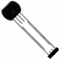
Sensor
Figure 1. Relative motion of the target is detected by the dual Hall elements mounted on the Hall IC.
Pin 1 Side
Sensor Internal Differential Analog Signal, VPROC
BOP(#1) BOP(#2) BRP(#1)
+t
Rotating Target
Branded Face of Sensor
Sensor Internal Switch State Off
1 4
On
Off
On
+t
Sensor Output Signal, IOUT
Figure 2. This left-to-right (pin 1 to pin 4) direction of target rotation results in a high output signal when a tooth of the target gear is nearest the face of the sensor (see figure 3). A right-to-left (pin 4 to pin 1) rotation inverts the output signal polarity.
+t
Figure 3. The magnetic profile reflects the geometry of the target, allowing the ATS643 to present an accurate digital output response.
Allegro MicroSystems, Inc. 115 Northeast Cutoff, Box 15036 Worcester, Massachusetts 01615-0036 (508) 853-5000 www.allegromicro.com
9
�ATS643LSH
Self-Calibrating, Zero-Speed Differential Gear Tooth Sensor with Continuous Update
release point, BRP , the switch toggles from on to off. As shown in panel C of figure 4, threshold levels for the ATS643 switchpoints are established dynamically as function of the peak input signal levels. The ATS643 incorporates an algorithm that continuously monitors the system and updates the switching thresholds accordingly. The switchpoint for each edge is determined by the detection of the previous two edges. In this manner, variations are tracked in real time.
VPROC is directly proportional to the magnetic flux density, B, induced by the target and sensed by the Hall elements. When VPROC transitions through a switchpoint from the appropriate higher or lower level, it triggers sensor switch turn-on and turnoff. As shown in figure 3, when the switch is in the off state, as VPROC rises through a certain limit, referred to as the operate point, BOP , the switch toggles from off to on. When the switch is in the on state, as VPROC falls below BOP to a certain limit, the
(A) TEAG varying; cases such as eccentric mount, out-of-round region, normal operation position shift
(B) Internal analog signal, VPROC, typically resulting in the sensor
V+
Smaller TEAG
Larger TEAG
Smaller TEAG
Target
Target
VPROC (V)
Sensor
Smaller TEAG
Sensor
Larger TEAG
Hysteresis Band (Delimited by switchpoints) 0 Target Rotation (°) 360
(C) Referencing the internal analog signal, VPROC, to continuously update device response
BHYS Switchpoint 1 2 3 4 BOP(#1) BRP(#1) BOP(#2) BRP(#2) BOP(#3) BRP(#3) BOP(#4) BRP(#4)
Determinant Peak Values Pk(#1), Pk(#2) Pk(#2), Pk(#3) Pk(#3), Pk(#4) Pk(#4), Pk(#5) Pk(#5), Pk(#6) Pk(#6), Pk(#7) Pk(#7), Pk(#8) Pk(#8), Pk(#9)
V+
Pk(#1) Pk(#3) Pk(#5) BOP(#2) BOP(#3) BRP(#1) Pk(#4) Pk(#2) BHYS(#1) BHYS(#2) BRP(#2) Pk(#6) Pk(#8) BHYS(#3) BRP(#3) BOP(#4) Pk(#7)
Pk(#9)
VPROC (V)
BOP(#1)
BRP(#4)
BHYS(#4)
t+
Figure 4. The Continuous Update algorithm allows the Allegro sensor to immediately interpret and adapt to significant variances in the magnetic field generated by the target as a result of eccentric mounting of the target, out-of-round target shape, elevation due to lubricant build-up in journal gears, and similar dynamic application problems that affect the TEAG (Total Effective Air Gap). The algorithm is used to dynamically establish and subsequently update the device switchpoints (BOP and BRP). The hysteresis, BHYS(#x), at each target feature configuration results from this recalibration, ensuring that it remains properly proportioned and centered within the peak-to-peak range of the internal analog signal, VPROC. As shown in panel A, the variance in the target position results in a change in the TEAG. This affects the sensor as a varying magnetic field, which results in proportional changes in the internal analog signal, VPROC, shown in panel B. The Continuous Update algorithm is used to establish accurate switchpoints based on the fluctuation of VPROC, as shown in panel C.
Allegro MicroSystems, Inc. 115 Northeast Cutoff, Box 15036 Worcester, Massachusetts 01615-0036 (508) 853-5000 www.allegromicro.com
10
�ATS643LSH
Self-Calibrating, Zero-Speed Differential Gear Tooth Sensor with Continuous Update
however, it allows the device to optimize for continuous update yielding adaptive sensing during Running mode. As shown in figure 5, the first three high peak signals are used to calibrate AGC. However, there is a slight variance in the duration of initialization, depending on what target feature is nearest the sensor when power-on occurs.
Power-On State Operation. The ATS643 is guaranteed to power-on in the high current state, ICC(High). Initial Edge Detection. The device self-calibrates using the initial teeth sensed, and then enters Running mode. This results in reduced accuracy for a brief period (less than four teeth),
Target (Gear) Sensor Position 1
2
3
4
VPROC
Power-on over valley 1 Output
Start Mode Hysteresis Overcome AGC Calibration Running Mode
VPROC Power-on at rising edge 2 Output
Start Mode Hysteresis Overcome AGC Calibration Running Mode
VPROC Power-on over tooth 3 Output
Start Mode Hysteresis Overcome
AGC Calibration
Running Mode
VPROC Power-on at falling edge 4 Output
Start Mode Hysteresis Overcome
AGC Calibration
Running Mode
Figure 5. Power-on initial edge detection. This figure demonstrates four typical power-on scenarios. All of these examples assume that the target is moving relative to the sensor in the direction indicated. The length of time required to overcome Start Mode Hysteresis, as well as the combined effect of whether it is overcome in a positive or negative direction plus whether the next edge is in that same or opposite polarity, affect the point in time when AGC calibration begins. Three high peaks are always required for AGC calibration.
Allegro MicroSystems, Inc. 115 Northeast Cutoff, Box 15036 Worcester, Massachusetts 01615-0036 (508) 853-5000 www.allegromicro.com
11
�ATS643LSH
Self-Calibrating, Zero-Speed Differential Gear Tooth Sensor with Continuous Update
A typical scenario is shown in figure 6. The hysteresis, POHYS, is a minimum level of the peak-to-peak amplitude of the internal analog electrical signal, VPROC, that must be exceeded before the ATS643 starts to compute switchpoints.
Start Mode Hysteresis. This feature helps to ensure optimal self-calibration by rejecting electrical noise and low-amplitude target vibration during initialization. This prevents AGC from calibrating the sensor on such spurious signals. Calibration can be performed using the actual target features.
Target, Gear
Sensor Position Relative to Target Target Magnetic Profile
1
2
5
Differential Signal, VPROC Start Mode Hysteresis, POHYS
BOP(#1) BRP(#1) BOP(#2)
1
Output Signal, IOUT
2 3 4 5
Figure 6. Operation of Start Mode Hysteresis Position 1. At power-on, the ATS643 begins sampling VPROC. Position 2. At the point where the Start Mode Hysteresis is exceeded, the device begins to establish switching thresholds (BOP and BRP) using the Continuous Update algorithm. After this point, Start Mode Hysteresis is no longer a consideration. Note that a valid VPROC value exceeding the Start Mode Hysteresis can be generated either by a legitimate target feature or by excessive vibration. Position 3. In this example, the first switchpoint transition is through BOP . and the output transitions from high to low. If the first switchpoint transition had been through BRP (such as position 4), no output transition would occur because IOUT already would be in the high polarity. The first transition would occur at position 5 (BOP).
Allegro MicroSystems, Inc. 115 Northeast Cutoff, Box 15036 Worcester, Massachusetts 01615-0036 (508) 853-5000 www.allegromicro.com
12
�ATS643LSH
Self-Calibrating, Zero-Speed Differential Gear Tooth Sensor with Continuous Update
power-on, the device determines the peak-to-peak amplitude of the signal generated by the target. The gain of the sensor is then automatically adjusted. Figure 8 illustrates the effect of this feature. Automatic Offset Adjust (AOA). The AOA is patented circuitry that automatically cancels the effects of chip, magnet, and installation offsets. (For capability, see Dynamic Offset Cancellation, in the Operating Characteristics table.) This circuitry is continuously active, including both during power-on mode and running mode, compensating for any offset drift. Continuous operation also allows it to compensate for offsets induced by temperature variations over time. Assembly Description. The ATS643 is integrally molded into a plastic body that has been optimized for size, ease of assembly, and manufacturability. High operating temperature materials are used in all aspects of construction.
Undervoltage Lockout. When the supply voltage falls below the minimum operating voltage, VCC(UV), ICC goes high and remains high regardless of the state of the magnetic gradient from the target. This lockout feature prevents false signals, caused by undervoltage conditions, from propagating to the output of the sensor. Power Supply Protection. The device contains an on-chip regulator and can operate over a wide VCC range. For devices that need to operate from an unregulated power supply, transient protection must be added externally. For applications using a regulated line, EMI/RFI protection may still be required. Contact Allegro Microsystems for information on the circuitry needed for compliance with various EMC specifications. Refer to figure 7 for an example of a basic application circuit. Automatic Gain Control (AGC). This feature allows the device to operate with an optimal internal electrical signal, regardless of the air gap (within the AG specification). At
Ferrous Target Mechanical Profile
V+
(Optional) 1 VCC
Internal Differential Analog Signal Response, without AGC
AGLarge
2
ATS643
3
0.01 μF (Optional)
AGSmall
V+ Internal Differential Analog Signal Response, with AGC AGSmall AGLarge
4
100 Ω
Figure 7. Typical basic circuit for proper device operation.
Figure 8. Automatic Gain Control (AGC). The AGC function corrects for variances in the air gap. Differences in the air gap cause differences in the magnetic field at the device, but AGC prevents that from affecting device performance, a shown in the lowest panel.
Allegro MicroSystems, Inc. 115 Northeast Cutoff, Box 15036 Worcester, Massachusetts 01615-0036 (508) 853-5000 www.allegromicro.com
13
�ATS643LSH
Self-Calibrating, Zero-Speed Differential Gear Tooth Sensor with Continuous Update
Power Derating
Example: Reliability for VCC at TA = 150°C, package L-I1, using minimum-K PCB Observe the worst-case ratings for the device, specifically: RθJA = 126°C/W, TJ(max) = 165°C, VCC(max) = 24 V, and ICC(max) = 16 mA. Calculate the maximum allowable power level, PD(max). First, invert equation 3: ΔTmax = TJ(max) – TA = 165 °C – 150 °C = 15 °C This provides the allowable increase to TJ resulting from internal power dissipation. Then, invert equation 2: PD(max) = ΔTmax ÷ RθJA = 15°C ÷ 126 °C/W = 119 mW Finally, invert equation 1 with respect to voltage: VCC(est) = PD(max) ÷ ICC(max) = 119 mW ÷ 16 mA = 7 V The result indicates that, at TA, the application and device can dissipate adequate amounts of heat at voltages ≤VCC(est). Compare VCC(est) to VCC(max). If VCC(est) ≤ VCC(max), then reliable operation between VCC(est) and VCC(max) requires enhanced RθJA. If VCC(est) ≥ VCC(max), then operation between VCC(est) and VCC(max) is reliable under these conditions.
The device must be operated below the maximum junction temperature of the device, TJ(max). Under certain combinations of peak conditions, reliable operation may require derating supplied power or improving the heat dissipation properties of the application. This section presents a procedure for correlating factors affecting operating TJ. (Thermal data is also available on the Allegro MicroSystems Web site.) The Package Thermal Resistance, RθJA, is a figure of merit summarizing the ability of the application and the device to dissipate heat from the junction (die), through all paths to the ambient air. Its primary component is the Effective Thermal Conductivity, K, of the printed circuit board, including adjacent devices and traces. Radiation from the die through the device case, RθJC, is relatively small component of RθJA. Ambient air temperature, TA, and air motion are significant external factors, damped by overmolding. The effect of varying power levels (Power Dissipation, PD), can be estimated. The following formulas represent the fundamental relationships used to estimate TJ, at PD. PD = VIN × IIN ΔT = PD × RθJA TJ = TA + ΔT (1) (2) (3)
For example, given common conditions such as: TA= 25°C, VCC = 12 V, ICC = 4 mA, and RθJA = 140 °C/W, then: PD = VCC × ICC = 12 V × 4 mA = 48 mW ΔT = PD × RθJA = 48 mW × 140 °C/W = 7°C TJ = TA + ΔT = 25°C + 7°C = 32°C A worst-case estimate, PD(max), represents the maximum allowable power level (VCC(max), ICC(max)), without exceeding TJ(max), at a selected RθJA and TA.
Allegro MicroSystems, Inc. 115 Northeast Cutoff, Box 15036 Worcester, Massachusetts 01615-0036 (508) 853-5000 www.allegromicro.com
14
�ATS643LSH
Self-Calibrating, Zero-Speed Differential Gear Tooth Sensor with Continuous Update
Package SH, 4-pin SIP
5.5 .217
B
8.0
.315
5.8
.228
4.0 5.0 .244
.157 1.7 .067 1 2 3 4
A
0.38 .015
1.08 .043 1 .039
20.95 .825 13.05 .514
A
0.6 .024
D
0.6 .024 1.27 .050 Dimensions in millimeters. Untoleranced dimensions are nominal. U.S. Customary dimensions (in.) in brackets, for reference only A Dambar removal protrusion (16X)
B Metallic protrusion, electrically connected to pin 4 and substrate (both sides) C Active Area Depth D Thermoplastic Molded Lead Bar for alignment during shipment
Allegro MicroSystems, Inc. 115 Northeast Cutoff, Box 15036 Worcester, Massachusetts 01615-0036 (508) 853-5000 www.allegromicro.com
15
�ATS643LSH
Self-Calibrating, Zero-Speed Differential Gear Tooth Sensor with Continuous Update
The products described herein are manufactured under one or more of the following U.S. patents: 5,045,920; 5,264,783; 5,442,283; 5,389,889; 5,581,179; 5,517,112; 5,619,137; 5,621,319; 5,650,719; 5,686,894; 5,694,038; 5,729,130; 5,917,320; and other patents pending. Allegro MicroSystems, Inc. reserves the right to make, from time to time, such departures from the detail specifications as may be required to permit improvements in the performance, reliability, or manufacturability of its products. Before placing an order, the user is cautioned to verify that the information being relied upon is current. Allegro products are not authorized for use as critical components in life-support devices or systems without express written approval. The information included herein is believed to be accurate and reliable. However, Allegro MicroSystems, Inc. assumes no responsibility for its use; nor for any infringement of patents or other rights of third parties which may result from its use. Copyright © 2004, 2006 Allegro MicroSystems, Inc.
Allegro MicroSystems, Inc. 115 Northeast Cutoff, Box 15036 Worcester, Massachusetts 01615-0036 (508) 853-5000 www.allegromicro.com
16
�