2916
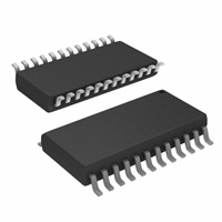
UDN2916B (DIP)
OUT 1A OUT 2A E2 S E NS E 2 OUT 2 B G R OUND G R OUND I 02 I 12 P HAS E 2 V REF 2 RC 2 1 2 3 4 5 6 7 8
P WM 1
DUAL FULL-BRIDGE PWM MOTOR DRIVER
VBB L OAD S UP P LY E1 S E NS E 1 OUT 1B I 01 G R OUND G R OUND I 11 P HAS E 1 V REF 1 RC 1 LOG IC S UP P LY
24 23
1 2
22 21 20 19 18 17 θ1 16 15 14 V CC 13
The UDN2916B, UDN2916EB, and UDN2916LB motor drivers are designed to drive both windings of a bipolar stepper motor or bidirectionally control two dc motors. Both bridges are capable of sustaining 45 V and include internal pulse-width modulation (PWM) control of the output current to 750 mA. The outputs have been optimized for a low output saturation voltage drop (less than 1.8 V total source plus sink at 500 mA). For PWM current control, the maximum output current is determined by the user’s selection of a reference voltage and sensing resistor. Two logic-level inputs select output current limits of 0, 33, 67, or 100% of the maximum level. A PHASE input to each bridge determines load current direction. The bridges include both ground clamp and flyback diodes for protection against inductive transients. Internally generated delays prevent cross-over currents when switching current direction. Special power-up sequencing is not required. Thermal protection circuitry disables the outputs if the chip temperature exceeds safe operating limits. The UDN2916B is supplied in a 24-pin dual in-line plastic batwing package with a copper lead-frame and heat sinkable tabs for improved power dissipation capabilities. The UDN2916EB is supplied in a 44lead power PLCC for surface mount applications. The UDN2916LB is supplied in a 24-lead surface-mountable SOIC. Their batwing construction provides for maximum package power dissipation in the smallest possible construction. The UDN2916B, UDN2916EB, and UDN2916LB are available for operation from –20°C to 85°C. The UDQ2916B and UDQ2916LB are available for operation from –40°C to 105°C. All packages are lead (Pb) free, with 100% matte tin leadframe.
Data Sheet 29319.20L
9 9 10 11 12 θ2
P WM 2
Dwg. P P -005
ABSOLUTE MAXIMUM RATINGS
at TJ ≤ 150°C
Motor Supply Voltage, VBB .................... 45 V Output Current, IOUT (Peak) ........................................ +1.0 A (Continuous) .......................... +750 mA Logic Supply Voltage, VCC ................... 7.0 V Logic Input Voltage Range, VIN ......................... - 0.3 V to VCC+0.3 V Output Emitter Voltage, VE .................. 1.5 V Package Power Dissipation, PD ........................................................ See Graph Operating Temperature Range, TA ................................. -20°C to +85°C Storage Temperature Range, TS ............................... - 55°C to +150°C
Output current rating may be limited by duty cycle, ambient temperature, and heat sinking. Under any set of conditions, do not exceed the specified peak current rating or a junction temperature of +150°C.
FEATURES
■ ■ ■ ■ ■ ■ ■ 750 mA Continuous Output Current 45 V Output Sustaining Voltage Internal Clamp Diodes Internal PWM Current Control Low Output Saturation Voltage Internal Thermal Shutdown Circuitry Similar to Dual PBL3717, UC3770
�2916 DUAL FULL-BRIDGE MOTOR DRIVER
Selection Guide
Part Number Pb-free * Package Packing Ambient Temperature (°C) –20 to 85 –40 to 105 –20 to 85 –20 to 85 –20 to 85 –20 to 85 –40 to 105
UDN2916B-T UDQ2916B-T UDN2916EB-T UDN2916EBTR-T UDN2916LB-T UDN2916LBTR-T UDQ2916LBTR-T
*
Yes Yes Yes Yes Yes Yes Yes
24-Pin DIP 24-Pin DIP 44-Lead PLCC 44-Lead PLCC 24-Lead SOIC 24-Lead SOIC 24-Lead SOIC
15 per tube 15 per tube 17 per tube 450 per reel 31 per tube 1000 per reel 1000 per reel
Pb-based variants are being phased out of the product line. The variants cited in this footnote are in production but have been determined to be LAST TIME BUY. This classification indicates that sale of this device is currently restricted to existing customer applications. The variants should not be purchased for new design applications because obsolescence in the near future is probable. Samples are no longer available. Status change: October 31, 2006. Deadline for receipt of LAST TIME BUY orders: April 27, 2007. These variants include: UDN2916B, UDQ2916EB, UDN2916EB, UDQ2916EBTR, UDN2916EBTR, UDN2916LB, UDQ2916LB, UDQ2916LBTR, and UDN2916LBTR.
2
115 Northeast Cutoff, Box 15036 Worcester, Massachusetts 01615-0036 (508) 853-5000
�2916 DUAL FULL-BRIDGE MOTOR DRIVER
UDN2916EB (PLCC)
LOGIC SUPPLY LOAD SUPPLY
5
SENSE 1
PHASE 1
OUT 1A
OUT 1B
ALLOWABLE PACKAGE POWER DISSIPATION IN WAT TS
VREF 1
43
42
41
RC1
E
I01
I11
R JT = 6.0°C/W
1
44
40
6
5
4
3
2
1
1
VCC 39 GND
4
SUFFIX 'EB', R
JA
= 30°C/W
JA
GND
7 8
VBB
PWM 1
SUFFIX 'B', R
= 40°C/W
38 37 36 35 34 33
9 10 11 12 13 14 15 16 GND 17 NC
NO CONNECTION 19 21 OUT 2A 18 E2 20
3
1
2
2
32 31 30 29 NC
NO CONNECTION 22 OUT 2B 23 I02 24 I12 25
2
1
SUFFIX 'LB', R JA = 55°C/W*
PWM 2
GND
0
26
27
SENSE 2
V REF 2
PHASE 2
RC 2
28
25
50
75 100 TEMPERATURE IN °C
125
150
Dwg. GP-035B
Dwg. PP-006A
*Measured on a single-layer board, with 1 sq. in. of 2 oz copper area. For additional information, refer to the Allegro Web site.
UDN2916LB (SOIC)
'B' PACKAGE, CHANNEL 1 PIN NUMBERS SHOWN.
PWM CURRENT-CONTROL CIRCUITRY
VBB
24
I
02
1
PWM 2
24 23 22 2 21 20 19
VBB
LOAD SUPPLY OUT2B SENSE 2 E2 OUT 2A GROUND GROUND OUT1A E1 SENSE 1 OUT1B I 01
I 12 PHASE 2 V REF 2 RC 2 GROUND GROUND LOGIC SUPPLY RC 1 V REF 1 PHASE 1 I 11
2 3 4 5 6 7 8 9 9 V CC
2
1
OUT B
21
OUT A V REF 15 20 k 10 40 k I 0 20 I 1 17 10 k RS
23
E SENSE – RC
22
+
ONE SHOT
14
SOURCE DISABLE
18 17 16 1 15
RC CT
CC
RT
10
PWM 1
Dwg. EP-007B
11 12
1
14 13
TRUTH TABLE
PHASE O U TA H L OUTB L H H L
Dwg. PP-047
3
115 Northeast Cutoff, Box 15036 Worcester, Massachusetts 01615-0036 (508) 853-5000 Copyright © 1994, 2003, 2007 Allegro MicroSystems, Inc.
�2916 DUAL FULL-BRIDGE MOTOR DRIVER
ELECTRICAL CHARACTERISTICS at TA = +25°C, TJ ≤ 150°C, VBB = 45 V, VCC = 4.75 V to 5.25 V, VREF = 5.0 V (unless otherwise noted).
Limits Characteristic Output Drivers (OUTA or OUTB) Motor Supply Range Output Leakage Current VBB ICEX VOUT = VBB VOUT = 0 Output Sustaining Voltage Output Saturation Voltage VCE(sus) VCE(SAT) IOUT = ± 750 mA, L = 3.0 mH Sink Driver, IOUT = +500 mA Sink Driver, IOUT = +750 mA Source Driver, IOUT = –500 mA Source Driver, IOUT = –750 mA Clamp Diode Leakage Current Clamp Diode Forward Voltage Driver Supply Current IR VF IBB(ON) IBB(OFF) Control Logic Input Voltage VIN(1) VIN(0) Input Current IIN(1) All inputs All inputs VIN = 2.4 V VIN = 0.8 V Reference Voltage Range Current Limit Threshold (at trip point) VREF VREF / VSENSE Operating I0 = I1 = 0.8 V I0 = 2.4 V, I1 = 0.8 V I0 = 0.8 V, I1 = 2.4 V Thermal Shutdown Temperature Total Logic Supply Current TJ ICC(ON) ICC(OFF) Fixed Off-Time toff I0 = I1 = 0.8 V, No Load I0 = I1 = 2.4 V, No Load RT = 56 kΩ, CT = 820 pF 2.4 — — — 1.5 9.5 13.5 25.5 — — — — — —