2019/2/20
EC11 Series - Basic information
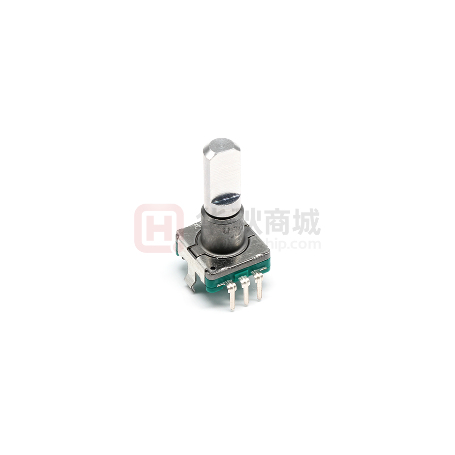
11mm Size Metal Shaft Type EC11 Series
Structure
Vertical
Actuator configuration
Flat
Actuator length
20mm
Number of detent
30
Number of pulse
15
Push-on switch
With
Travel of push-on switch
0.5mm
Operating life
15,000 cycles
Operating temperature range
-40℃ to +85℃
Electrical
performance
Ratings
10mA 5V DC
Output signal
Two phase A and B
Max./min. operating 10mA/1mA
current(Resistive
load)
Insulation resistance 100MΩ min. 250V DC
Mechanical
performance
Push-on switch
specifications
Voltage proof
300V AC for 1 minute or 360V AC for 2s
Detent torque
10±7mN·m
Push-pull strength
100N
Contact
arrangement
Single pole single throw (Push-on)
Travel
0.5±0.3mm
Operating force
6(+2.5, -2)N
Rating
0.1A 5V DC (500μA 5V DC min. ratings)
Contact resistance
100mΩ max./200mΩ max.
About Cookies on this site:
(Initial
This site uses cookies to improve your online experience. By continuing to use this site
without changing your cookie preferences, we will assume that you are agreeing to our use
f
ki
F
i f
ti
i it
T
fU
https://www.alps.com/prod/info/E/HTML/Encoder/Incremental/EC11/EC11E15244G1.html
Accept
1/5
�2019/2/20
EC11 Series - Basic information
of cookies. For more information, visit our Terms of Use.
performance/After
lifetime)
Operating life
Minimum order unit Japan
20,000 times
1,200
(pcs.)
Export
2,400
Dimensions
Mounting Hole Dimensions
About Cookies on this site:
This site uses cookies to improve your online experience. By continuing to use this site
without changing your cookie preferences, we will assume that you are agreeing to our use
f
ki
F
i f
ti
i it
T
fU
https://www.alps.com/prod/info/E/HTML/Encoder/Incremental/EC11/EC11E15244G1.html
Accept
2/5
�2019/2/20
EC11 Series - Basic information
of cookies. For more information, visit our Terms of Use.
Viewed from mounting side.
Output Wave
Sliding Noise
About Cookies on this site:
This site uses cookies to improve your online experience. By continuing to use this site
At R=5kΩ Chattering: 3ms max. Bounce: 2ms max.
without changing your cookie preferences, we will assume that you are agreeing to our use
f
ki
F
i f
ti
i it
T
fU
https://www.alps.com/prod/info/E/HTML/Encoder/Incremental/EC11/EC11E15244G1.html
Accept
3/5
�2019/2/20
EC11 Series - Basic information
of cookies. For more information, visit our Terms of Use.
Packing Specifications
Tray
Number of packages 1 case / Japan
(pcs.)
1 case / export
1,200
2,400
packing
Export package measurements (mm)
540×360×250
Soldering Conditions
Reference for Dip Soldering
Preheating
Dip soldering
Soldering surfacetemperature
100℃ max.
Heating time
2 min. max.
Soldering temperature
260±5℃
Soldering time
5±1s
No. of solders
2 time max.
Reference for Hand Soldering
Tip temperature
350℃ max.
Soldering time
3s max.
No. of solders
1 time
Product Varieties
Single-shaft Type
1) Knurled Type
Unit : mm
Style (Shaft diameter : φ6)
2) Flat Type
About Cookies on this site:
Style (Shaft diameter : φ6)
This site uses cookies to improve your online experience. By continuing to use this site
without changing your cookie preferences, we will assume that you are agreeing to our use
f
ki
F
i f
ti
i it
T
fU
https://www.alps.com/prod/info/E/HTML/Encoder/Incremental/EC11/EC11E15244G1.html
Unit : mm
Accept
4/5
�2019/2/20
EC11 Series - Basic information
of cookies. For more information, visit our Terms of Use.
Values in parentheses apply to products without push-on switch.
3) Slotted Type
Unit : mm
Style (Shaft diameter : φ6)
Notes are common to this series/models.
1. This site catalog shows only outline specifications. When using the products, please obtain formal
specifications for supply.
2. Please place purchase orders per minimum order unit (integer).
3. Products other than those listed in the above chart are also available. Please contact us for details.
4. This products can be used in vehicles.
Although these products are designed to perform over a wide operating temperature range, please
ensure that you receive and read the formal delivery specifications before use.
About Cookies on this site:
This site uses cookies to improve your online experience. By continuing to use this site
without changing your cookie preferences, we will assume that you are agreeing to our use
f
ki
F
i f
ti
i it
T
fU
https://www.alps.com/prod/info/E/HTML/Encoder/Incremental/EC11/EC11E15244G1.html
Accept
5/5
�
很抱歉,暂时无法提供与“EC11E15244G1”相匹配的价格&库存,您可以联系我们找货
免费人工找货- 国内价格
- 1+16.06610
- 10+13.90620
- 30+12.55490
- 120+10.16400
- 480+9.54030
- 960+9.26310
- 国内价格
- 1+13.63180
- 10+11.79920
- 30+10.65260
- 国内价格 香港价格
- 1+40.869721+5.26890
- 5+35.097365+4.52473
- 10+32.8633510+4.23672
- 25+30.1289625+3.88421
- 50+28.2117450+3.63704
- 100+26.41183100+3.40500
- 250+24.19773250+3.11956
- 500+22.63905500+2.91861
- 1000+21.173031000+2.72962