DOCUMENT No.
KHH-703
TITLE
PRODUCT SPECIFICATIONS
製
品
仕
様
For reference
SKHHAQA010
1. General 一般事項
1.1 Application
適用範囲
1.2 Operating temperature range
1.3 Storage temperature range
1.4 Test conditions 試験状態
3. Type of actuating 動作形式
回路形式
5. Ratings 定格
5.1 Maximum ratings 最大定格
5.2 Minimum ratings 最小定格
6. Electrical specification
6.3
参考
外観、形状、寸法
2.2 Style and dimensions 形状、寸法
6.2
1/6
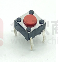
This specification is applied to TACT switches which have no keytop.
この規格書は、キートップなしのタクトスイッチについて 適用する。
使用温度範囲:
-40 ~ +90 ℃ (normal humidity,normal air pressure 常湿・常圧)
保存温度範囲:
-40 ~ +90 ℃ (normal humidity,normal air pressure 常湿・常圧)
Unless otherwise specified, the atmospheric conditions for making measurements and tests are as follows.
試験及び測定は特に規定がない限り以下の標準状態のもとで行う。
Normal temperature
常
温: (Temperature 温度 5~35℃)
Normal humidity
常
湿: (Relative humidity 湿度 25~85%)
Normal air pressure
常
圧: (Air pressure 気圧 86~106kPa)
If any doubt arise from judgement, tests shall be conducted at the following conditions.
ただし、判定に疑義を生じた場合は以下の基準状態で行う。
Ambient temperature
温
度: 20±2℃
Relative humidity
相対湿度: 60~70%
Air pressure
気
圧: 86~106kPa
2. Appearance, style and dimensions
2.1 Appearance 外観
6.1
書
Date:.201707
PRODUCT No.
4. Contact arrangement
PAGE
There shall be no defects that affect the serviceability of the product.
性能上有害な欠陥があってはならない。
Refer to the assembly drawings. 製品図による。
Tactile feedback
タクティールフィードバック
1 poles 1 throws
1 回路 1 接点
(Details of contact arrangement are given in the assembly drawings
回路の詳細は製品図による)
12 V DC 50 mA
1 V DC 10μA
電気的性能
Items
項 目
Contact resistance
接 触 抵 抗
Test conditions
試 験 条 件
Applying a below static load to the center of the stem, measurements shall be
made.
スイッチ操作部中央に下記の静荷重を加え,測定する。
(1) Depression
押圧力 : 5.10 N
(2) Measuring method 測定方法 : 1 kHz small-current contact resistance meter
or voltage drop method at 5VDC 10mA.
1kHz微少電流接触抵抗計,又はDC5V 10mA電圧降下
法
Insulation
resistance
絶 縁 抵 抗
Measurements shall be made following the test set forth below:
下記条件で試験を行った後,測定する。
(1) Test voltage
印加電圧: 100 V DC for 1 min.
(2) Applied position
印加場所:Between all terminals. And if there is a metal
frame, between terminals and ground(frame)
端子間,金属フレームがある場合は,端子と
金属フレーム間
Voltage proof
耐 電 圧
Measurements shall be made following the test set forth below:
下記条件で試験を行った後,測定する。
(1) Test voltage
印加電圧: 250 V AC (50~60Hz)
(2) Duration
印加時間:1 min
(3) Applied position
印加場所:Between all terminals. And if there is a metal
frame, between terminals and ground(frame)
端子間,金属フレームがある場合は,端子と
金属フレーム間
ALPS ELECTRIC CO.,LTD.
Criteria
100 mΩ Max.
判 定 基 準
100 MΩ Min.
There shall be no breakdown.
絶縁破壊のないこと。
�DOCUMENT No.
KHH-703
TITLE
PRODUCT SPECIFICATIONS
製
品
仕
様
For reference
SKHHAQA010
Items
Bounce
バウンス
2/6
Date:.201707
PRODUCT No.
6.4
PAGE
書
項
目
参考
Test conditions
試 験 条 件
Lightly striking the center of the stem at a rate encountered in normal use
(3 to 4 operations per s ),bounce shall be tested at "ON" and "OFF".
スイッチ操作部の中央部を通常の使用状態(3~4回/秒)で軽く打鍵し,ON時及び
OFF時のバウンスを測定する。
Criteria
判 定 基 準
ON bounce : 5 ms Max.
OFF bounce: 5 ms Max.
Switch
5V
"ON"
7. Mechanical specification
7.1
7.2
5kΩ
Oscilloscope
オシロスコープ
"OFF"
機械的性能
Items
項 目
Operating force
作 動 力
Test conditions
試 験 条 件
Placing the switch such that the direction of switch operation is vertical and
then gradually increasing the load applied to the center of the stem, the
maximum load required for the switch to come to a stop shall be measured.
スイッチの操作方向が垂直になる様にスイッチを設置し,操作部中央部に徐々に荷重を
加え,操作部が停止するまでの最大荷重を測定する。
Criteria
2.55 ± 0.69 N
Travel
移 動
Placing the switch such that the direction of switch operation is vertical and
then applying a below static load to the center of the stem, the travel distance
for the switch to come to a stop shall be measured.
スイッチの操作方向が垂直になる様にスイッチを設置し,操作部中央部に以下の静荷重
を加え,操作部が停止するまでの距離を測定する。
(1) Depression
押圧力: 5.10 N
0.25 + 0.2 /- 0.1 mm
0.49 N Min.
量
7.3
Return force
復 帰 力
The sample switch is installed such that the direction of switch operation is
vertical and,upon depression of the stem in its center the travel distance,the
force of the stem to return tot its free position shall be measured.
スイッチの操作方向が垂直になる様にスイッチを設置し,操作部中央部を移動量押圧後,
操作部が復帰する力を測定する。
7.4
Stop strength
ストッパー強度
Placing the switch such that the direction of switch operation is vertical and
then a below static load shall be applied in the direction of stem operation.
スイッチの操作方向が垂直になる様にスイッチを設置し,スイッチの操作方向へ以下の
静荷重を加える。
(1) Depression
押圧力: 29.4 N
(2) Time
時 間: 60 s
7.5
Stem strength
ステム抜去強度
Placing the switch such that the direction of switch operation is vertical and
then the maximum force to withstand a pull applied opposite to the direction of
stem operation shall be measured.
スイッチの操作方向が垂直になる様にスイッチを設置し,操作部の操作方向とは反対方向
に操作部を引っ張って抜けない力である。
8. Environmental specification
判 定 基 準
There shall be no sign of damage
mechanically and electrically.
機械的,電気的に異常のないこと。
29.4 N
耐候性能
Items
項 目
Resistance to low
temperatures
耐 寒 性
Test conditions
試 験 条 件
Following the test set forth below the sample shall be left in normal
temperature and humidity conditions for 1 h before measurements are made:
次の試験後,常温,常湿中に1時間放置後測定する。
(1) Temperature 温
度 : -40 ± 2 ℃
(2) Time
時
間 : 96 h
(3) Waterdrops shall be removed. 水滴は取り除く。
8.2
Heat resistance
耐 熱 性
Following the test set forth below the sample shall be left in normal
temperature and humidity conditions for 1 h before measurements are made:
次の試験後,常温,常湿中に1時間放置後測定する。
(1) Temperature 温
度 : 90 ± 2 ℃
(2) Time
時
間 : 96 h
Item 6.
Item 7.1
Item 7.2
8.3
Moisture
resistance
耐 湿 性
Following the test set forth below the sample shall be left in normal
temperature and humidity conditions for 1 h before measurements are made:
次の試験後,常温,常湿中に1時間放置後測定する。
(1) Temperature
温
度 : 60 ± 2 ℃
(2) Time
時
間 : 96 h
(3) Relative humidity 相対湿度 : 90 ~ 95 %
(4) Waterdrops shall be removed. 水滴は取り除く。
Contact resistance 接触抵抗(Item 6.1) :
200 mΩ Max.
Insulation resistance 絶縁抵抗(Item 6.2) :
10 MΩ Min.
Item 6.3
Item 6.4
Item 7.1
Item 7.2
8.1
ALPS ELECTRIC CO.,LTD.
Criteria
判 定 基 準
Item 6.
Item 7.1
Item 7.2
�DOCUMENT No.
KHH-703
TITLE
PRODUCT SPECIFICATIONS
製
品
仕
様
For reference
SKHHAQA010
8.4
3/6
Date:.201707
PRODUCT No.
Items
項
Change of
temperature
温度サイクル
PAGE
書
目
参考
Test conditions
試 験 条 件
After below cycles of following conditions, the switch shall be allowed
to stand under normal room temperature and humidity conditions for 1 h, and
measurement shall be made. Water drops shall be removed.
下記条件で以下回数のサイクル試験後、常温常湿中に1時間放置し測定する。
ただし、水滴は取り除く。
Criteria
判 定 基 準
Item 6.
Item 7.1
Item 7.2
A = +90 ℃
B = -40 ℃
C=
2 h
D=
1 h
E=
2 h
F=
1 h
A
B
C
D
E
F
(1)Number of cycles
サイクル数 : 5 cycles
1 cycle
9. Endurance specification
耐久性能
Items
項 目
Operating life
動 作 寿 命
Test conditions
試 験 条 件
Measurements shall be made following the test set forth below:
下記条件で試験を行った後,測定する。
(1) 5 VDC 5 mA resistive load 抵抗負荷
(2) Rate of operation
動作速度 : 2 to 3 operations per s 回/秒
(3) Depression
押圧力 : 3.23 N
(4)Cycles of operation 動作回数 : 200,000 cycles 回
Criteria
判 定 基 準
Contact resistance 接触抵抗(Item 6.1) :
200 mΩ Max.
Insulation resistance 絶縁抵抗(Item 6.2) :
10 MΩ Min.
Bounce バウンス(Item 6.4) :
ON bounce : 10 ms Max.
OFF bounce: 10 ms Max.
Operating force 作動力(Item 7.1) :
-30 ~ +30 % of initial force
初期値に対して
Item 6.3
Item 7.2
9.2
Vibration
resistance
耐 振 性
Measurements shall be made following the test set forth below:
下記条件で試験を行った後,測定する。
(1)Vibration frequency range 振動数範囲: 10 ~ 55 Hz
(2)Total amplitude
全振幅: 1.5 mm
(3)Sweep ratio
掃引の割合: 10-55-10 Hz Approx. 1 min
約 1 分
(4)Method of changing the sweep vibration frequency: Logarithmic or uniform
掃引振動数の変化方法
対数又は一様掃引
(5)Direction of vibration: Three mutually perpendicular directions,including
振動の方向
the direction of the travel
スイッチ操作方向を中心とした垂直3方向
(6)Duration
振動時間: 2 h each ( 6 h in total) 各 2 時間 (計 6 時間)
Item 6.1
Item 7.1
Item 7.2
9.3
Shock
耐 衝 撃 性
Measurements shall be made following the test set forth below:
下記条件で試験を行った後,測定する。
(1)Acceleration
加速度: 784 m/s2
(2)Acting time
作用時間: 11 msec
(3)Test direction
試験方向: 6 directions
6 面
(4)Number of shocks 試験回数: 3 times per direction
( 18 times in total)
各方向各 3 回 (計 18 回)
Item 6.1
Item 7.1
Item 7.2
9.1
ALPS ELECTRIC CO.,LTD.
�DOCUMENT No.
KHH-703
TITLE
PRODUCT SPECIFICATIONS
製
品
仕
様
PAGE
書
4/6
Date:.201707
PRODUCT No.
For reference
SKHHAQA010
参考
10. Soldering conditions 半田付条件
10.1
10.2
Items
項 目
Hand soldering
手 半 田
Recommended conditions
Please practice according to below conditions.
以下の条件にて実施して下さい。
(1)Soldering temperature
半田温度 : 360 ℃ Max.
(2)Continuous soldering time
連続半田時間 : 3 s Max.
(3)Capacity of soldering iron 半田コテ容量 : 60 W Max.
(4)Excessive pressure shall not be applied to the terminal.
端子に異常加圧のないこと
(5)Safeguard the switch assembly against flux penetration from its top side.
スイッチの上面からフラックスが浸入しない様にして下さい。
Automatic flow
Soldering
オートディップ半田
In case an automatic flow soldering apparatus is used for soldering, adhere to the following conditions:
噴流式自動半田装置で,半田付けされる場合は,次の条件に従って下さい。
Items
(1)Preheat temperature
項 目
プリヒート温度
(2)Preheat time
プリヒート時間
(3)Flux foaming
フラックス発泡量
(4)Soldering temperature
件
Soldering conditions 半田付け条件
110 ℃ Max.
(Ambient temperature of printed circuit board on soldering side)
(プリント基板の半田付け面の周囲の温度)
To such an extend that flux will be kept flush with the printed circuit
board's top surface on which components are mounted. Preparatory flux must not be
applied to that side of printed circuit board on which components are mounted and
to the area where terminals are located.
プリント基板の部品実装面上にフラックスが周囲から上がらない程度にする。なお, プリント
基板の部品実装面上及びスイッチ端子部に予備フラックスが塗布されていないこと。
半田浸漬時間
260 ℃ Max.
5 s Max.
(6)Allowable frequency of soldering process
半田回数
2 times Max.
Twice soldering would be dipped after the temperature goes down to a normal
temperature.
2回目を行う場合は,スイッチが常温に戻ってから行うこと。
(7)Recommended printed circuit board
推奨プリント基板
Printed circuit board shall be paper phenol with single-sided pattern. Please do not
design a through-hole at and/or near the switch mounting area. Thickness of printed
circuit board is specified in the product drawing.
プリント基板は紙フェノール片面パターンを推奨します。スイッチ周辺にスルーホールを設
けないでください。基板板厚は製品図に記載しています。
(8)Recommended flux
推奨フラックス
Soldering flux shall be "EC-19S-8" (TAMURA KAKEN) or equivalent. (Specific gravity
of soldering flux shall be more than 0.81 at 20℃.)
フラックスについては,タムラ化研 "EC-19S-8"相当品を使用してください。
(20℃換算でフラックス比重0.81以上)
(9)Other precaution
ALPS ELECTRIC CO.,LTD.
奨 条
60 s Max.
半田温度
(5)Duration of solder immersion
推
その他注意事項
Safeguard the switch assembly against flux penetration from its top side.
スイッチの上面からフラックスが浸入しない様にして下さい。
�DOCUMENT No.
KHH-703
PRODUCT No.
SKHHAQA010
TITLE
PRODUCT SPECIFICATIONS
製
品
仕
様
PAGE
書
5/6
Date:.201707
For reference
参考
【Precaution in use】 ご使用上の注意
A. General 一般項目
A1. This product has been designed and manufacturfd for general electronic devices, such as audio devices, visual devices, home electronics,
Information devices and communication devices. In case this product is used for more sophisticated equipment requiring higher safety and reliability,
such as life support system, space & aviation devices, disaster prevention & security system, please make verification of comformity or check on us for
the details.
本製品はオーディオ機器,映像機器,家電機器,情報機器,通信機器などの一般電子機器用に設計・製造したものです。生命維持装置,宇宙・航空機器,防災・防犯機器
などの高度な安全性や信頼性が求められる用途に使用される場合は,貴社にて適合性の確認を頂くか,当社へご確認ください。
A2. This product is designed and manufactured assuming that it is to be used with the resistance for direct current. If you use other kinds of
resistance (inductive (L) or capacitive (C)), please let us know beforehand.
本製品は直流の抵抗負荷を想定して設計・製造されています。その他の負荷(誘導性負荷(L),容量性負荷(C))で使用される場合は,別途ご相談ください。
B. Soldering and assemble to PC board process 半田付,基板実装工程
B1. Note that if the load is applied to the terminals during soldering they might suffer deformation and defects in electrical performance.
端子をはんだ付けされる場合、端子に荷重が加わりますと条件によりガタ、変形及び電気的特性劣化のおそれがありますのでご注意下さい。
B2. If soldering is made under the temperature or duration exceeding our recommend condition, molded plastic body may be melt. We highly recommend
that soldering should be made under our recommended temperature conditions.
弊社推奨半田付け条件を越えた条件で半田付けされますとスイッチ樹脂部の溶けが発生する可能性があります。半田付けは弊社推奨条件範囲内で実施して
頂けるようにお願い致します。
B3. If you use a through-hole PCB or a PCB with smaller thickness than recommended, please previously check the soldering conditions adequately,
because there is larger heat stress.
スルーホールのプリント基板及び推奨板厚より薄い基板をご使用される場合は推奨基板よりも熱ストレスの影響が大きくなりますので半田付条件については事前に
十分な確認をして下さい。
B4. If you use a PCB with smaller thickness than recommended, please pay enough attention to rising of switches when mounted.
推奨板厚より薄い基板をご使用の際は,実装時のスイッチ浮きに十分ご注意下さい。
B5. When the switch is mounted on a printed circuit board, the case shall be held. And insert the product body to the specified fixing plane and
fix it giving it the horizontal position. If it isn't fixed horizontally, it may cause malfunction.
本スイッチをプリント基板へ取り付ける場合は,ケースを持って行って下さい。製品本体を規定の取付面まで挿入して水平になるように取り付けてください。
水平にならないまま取り付けますと,動作不良の要因となります。
B6. If the stem is given stress from the side, it may result in damages to switch functions. Therefore please handle it with extreme care.
When the switch is carried, any shock shall not be applied to the stem.
ステムに横からの力が加わりますと,スイッチの機能破壊につながる危険性がありますので取扱いは十分注意して下さい。
移動する場合はステムに衝撃が加わらない様に注意して下さい。
B7. Do not press the stem but the switch body when you correct rising of the switch mounted on PCB.
基板実装後スイッチの浮きを修正する際は,スイッチのステムを押さずにスイッチ本体を押す様にして下さい。
B8.Conditions for thermosetting oven. 熱硬化炉条件
When the board on which the switch is mounted has to be put in the oven so as to harden adhesive for other parts, the conditions shall be 160℃
at max. (on the parts mounted side of PCB), and not longer than 2 minutes.
スイッチを取り付けた後,他の部品の接着剤硬化等のため熱硬化炉を通す場合,条件は160℃以下(基板部品面の温度),2分以内として下さい。
B9.Take most care not to let flux foam penetrate the switch when you perform auto-dip soldering, which may sometimes produce too much foam. Take
special care when you have LED or grounded terminals.
オートディップの場合フラックスの発泡量過多によりフラックスがスイッチ内部に浸入する場合が有りますので十分にご注意ください。
(LED付・アース端子付の場合は特にご注意下さい)
C. Washing process 洗浄工程
C1. Following the soldering process, do not try to clean the switch with a solvent or the like.
半田付け後,溶剤等でスイッチを洗浄しないでください。
D. Mechanism design(switch layout) 機構設計
D1. The dimensions of a hole and pattern for mounting a printed circuit board shall refer to the recommended dimensions in the engineering drawings.
プリント基板取付穴及びパターンは,製品図に記載されている推奨寸法をご参照下さい。
D2. Do not use the switch in a manner that the stem will be given stress from the side. If you push the stem from the side, the switch may be broken.
ステムを横方向から押す様な使い方は避けて下さい。ステム先端に横方向から荷重が加わりますとスイッチが破壊される場合があります。
D3. Press the center of the stem. Click feel may be changed, if you press the edge. This is because the center will be displaced, depending on the
hinge structure or cumulative tolerances. When you use the hinge structure, take special care so that the keytop point to press the switch won't
move.
ステムのセンターを押す様にして下さい。ヒンジ構造及びセット上の累積公差によるセンターズレなどステムを端押しする状態では感触が変化する場合があります
ヒンジ構造の場合は,押下時ステム押し位置が移動しますので,特にご注意下さい。
D4. This switch is designed for unit construction that it is pressed by human operation. Please avoid using this switch as mechanical detecting function. In case such detecting
function is required, please consult with our detector switch section.
当スイッチは、直接人の操作を介してスイッチを押す構造にてご使用下さい。メカ的な検出機能へのご使用は、避けてください。検出機能には弊社検出スイッチをご使用下さい。
D5. The switch will be broken, if you give larger stress than specified. Take most care not to let the switch be given larger stress than specified.
(Refer to the strength of the stopper.)
スイッチ操作時に規定以上の荷重が加わるとスイッチが破損する場合が有ります。スイッチに規定荷重以上の力が加わらない様にご注意下さい。
(ストッパー強度参照)
ALPS ELECTRIC CO.,LTD.
�DOCUMENT No.
KHH-703
TITLE
PRODUCT No.
SKHHAQA010
PRODUCT SPECIFICATIONS
製
品
仕
様
PAGE
書
6/6
Date:.201707
For reference
参考
E. Using environment 使用環境
E1. Foreign matter invaded from outside.
外部侵入物
Since this switch does not have sealed structure, it may have contact failure caused by the dust from outside up to the environment.
当スイッチは密閉構造ではありませんので,使用環境によっては塵埃が内部に侵入し,接点障害を起こす場合があります。
When you use this switch, precaution must be taken against the dust.
The followings are examples of dust invasion:
Dusty environment 塵埃環境
ご使用の際はスイッチに異物が侵入しないようにご注意ください。
以下に塵埃侵入例を示します。ご参考にして下さい。
①Debris from the cut or hole of PCB in process, or wastes from
the PCB protection material (e.g. newspaper, foamed polystyrene etc.)
invaded the switch.
工程内における基板切断面や穴から発生するクズやPCB保護材(新聞紙,
発泡スチロール等)から出るゴミがスイッチに侵入した。
②Flux or powdered flux produced by stacking PCB's or excess foaming
invaded the switch.
基板重ねによりフラックス粉末がスイッチに侵入した。
※ When you need higher dust-proof, make selection among the switches of
"→"Indicates the route of invasion.
dust-proof types in our catalog.
"→"は侵入経路を示します。
より高い防塵性が必要な場合は,当社カタログより防塵タイプのスイッチ
を選定しご使用願います。
E2. In case this product is always used around a sulfurate hot spring where sulfide gas is generated or in a place where exhaust gas from
automobiles exists,take most care due to the switch performance might be affected.
硫黄系温泉地等常時ガスが発生する場所や自動車等の排気ガスの発生する場所で常時使用する場合、当製品の性能に影響を及ぼすおそれがありますので十分に
ご注意下さい。
E3. Follow the directions if you have parts/materials described below within the module where the switch is installed.
同一セット内に以下の様な部材に関しましては以下の点にご注意願います。
・For parts,rubber materials,adhesive agents,plywood,packing materials and lubricant used for the mechanical part of the device, do not use
those ones that may generate gas of sulfurization or oxidization.
部品,ゴム材料,接着剤,合板,機器の梱包材,機器内の駆動部に使用される潤滑剤については,硫化,酸化ガスを発生しないものを採用してください。
・When you use silicon rubber, grease, adhesive agents and oil, use those that will not generate low molecular siloxane gas. The low molecular
siloxane gas may form silicon dioxide coat on the SW contact part, resulting in the contact failure.
シリコン系ゴム,グリース,接着剤,オイルを使用される場合は,低分子シロキサンガスを発生しないものを使用してください。低分子シロキサンガスが
発生しますとSW接点部に2酸化珪素の被膜を形成して接点障害を引き起こす場合があります。
・When you apply chemical agents such as coating agents to the products, please let us know beforehand.
製品のコーティング剤等の薬品を付着させる場合は,別途ご相談ください。
E4. Do not use this switch in the atmosphere with high humidity or with bedewing probability, because such atmosphere may cause leak among terminals.
高湿度環境下,又は結露する可能性がある環境では,端子間の電流リークが発生する可能性が有りますので本スイッチはご使用にならないでください。
F. Storage method. 保管方法
F1. If you don't use the product immediately, store it as delivered in the following environment: with neither direct sunshine nor corrosive gas and
in normal temperatures. However, it is recommended that you should use it as soon as possible before six months pass.
製品は納入形態のまま常温,常湿で直射日光の当たらず腐食性ガスが発生しない場所に保管し納入から6ヶ月以内を限度として出来るだけ早くご使用ください。
F2. After you break the seal, you should put the remaining in a plastic bag to separate it from the outside and store it in the same environment
mentioned above. You should use it up as soon as possible.
開封後はポリフクロで外気との遮断を図り上記と同じ環境下で保管しすみやかにご使用下さい。
F3. Do not stack too many switches for strafe.
過剰な積み重ねは行わないで下さい。
G. Others. その他
G1. This specification will be invalid one year after it is issued, if you don't return it or don't place an order.
本仕様書は発行日より1年間を経過して,ご返却又はご発注の無い場合は,無効とさせていただきます。
G2. Please understand that the specifications other than electric and mechanical characteristics and outside dimensions may be changed at our own
discretion.
電気的,機械的特性,外観寸法および取付寸法以外につきましては,当社の都合により変更させて頂く事が有りますので,あらかじめ御了承下さい。
G3. Never use the product beyond the rating. It may catch fire. If you think that the product may be used beyond the rating due to some abnormal
conditions, you must take certain protective measures, such as a protective circuit to shut down the current.
定格を超えての使用は火災発生のおそれがありますので絶対に避けて下さい。また異常使用等で定格を超える恐れがある場合は保護回路等で電流遮断等の対策をし
て下さい。
G4. The flammability grade of the plastic used for this product is "94HB" by the UL Standard (slow burning). Therefore, either refrain from using it
in the place where it can catch fire, or take measures to preclude catching fire.
本製品に使用している樹脂等の燃焼グレードはUL規格の”94HB”(遅燃性グレード)相当を使用しております。つきましては類焼の恐れがある場所での使用
を禁止するか,類焼防止対策をお願いします。
G5. Though we are confident in switch quality, we cannot deny the possibility that they could fail due to short or open circuit. Therefore, if you use
a switch for a product requiring higher safety level, we would like you to verify in advance what effects your module would receive in case the switch
alone should fail. And secure safety as a whole system by introducing the fail-safe design, i.e. a protection network.
スイッチの品質には万全を尽くしていますが故障モードとしてショート、オープンの発生が皆無とは言えません。安全性が重視されるセットの設計に際しては、SWの
単品故障にたいしてセットとしての影響を事前にご検討いただき、保護回路、等のフェールセーフ設計のご検討を十分に行い安全を確保して頂きますようにお願い
します。
ALPS ELECTRIC CO.,LTD.
�