BOARD/WIRE-TO-BOARD
CONNECTORS
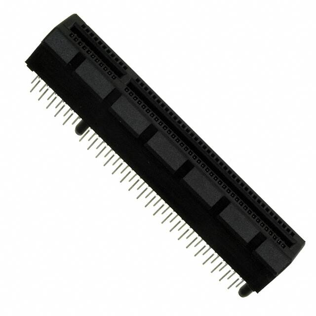
PCI EXPRESS® CARD
EDGE CONNECTORS
Extend differential signaling to 8.0GB/S for new generation systems
OVERVIEW
These 1.0mm pitch, vertical card edge connectors from FCI
enable all generations of PCI Express® signaling in desktop
PCs, workstations, and servers. The connector designs provide
support for 2.5Gb/s (Gen1), 5.0Gb/s (Gen2), and the recent
update to 8.0Gb/s (Gen3) per differential signal pair.
The base connector family provides x1, x4, x8, or x16 link
widths to suit different bandwidth requirements. The basic
bandwidth (x1) version supports a single PCI Express lane
and is typically used for I/O cards in desktop PCs. The x4 and
x8 connectors provide 64 and 98 contacts, respectively, for
server I/O. The high bandwidth versions (x16 lanes and higher)
are used for applications that require even more bandwidth,
such as graphics cards in desktop PCs or riser cards in servers.
FCI’s expansive range of available PCI Express card edge
connectors includes options for through-hole solder,
press-fit, surface-mount, or straddle-mount termination.
FEATURES & BENEFITS
TARGET MARKETS/APPLICATIONS
• B
ase connector range offers 1, 4, 8, or 16 serial
PCI Express links for different bandwidth requirements
• O
ptions for through-hole solder, press-fit,
surface-mount, or straddle-mount termination
• Data
• Desktop PCs
• Servers
• Workstations
• P
ress-fit version provides a solderless alternative for
termination to thick PCBs
• Industrial
• SHB Express™ backplanes per PICMG 1.3 spec
• L arger 200, 230 (x24), and 280-position vertical
connectors supply more lanes for server riser cards
• E
xpressModule™ versions provide an expanded lead-in
window for blind-mate server applications
• O
ptions for rugged stand-alone retention mechanism or a
x16 connector with annintegrated retention arm to secure
graphics cards during shipping and handling
• S traddle-mount connectors feature mounting ears for
additional mechanical support and a molded post to
assure proper alignment to the host PCB
• RoHS-compliant connector versions are available
140410-BWB_pciexpresscard.indd 1
2014-4-10 11:48:19
�PCI EXPRESS® CARD EDGE CONNECTORS
PCI EXPRESS® VERTICAL CARD EDGE CONNECTORS,
THROUGH-HOLE SOLDER
Description
Part Numbers
36 (x1), 64 (x4), 98 (x8), and 164 (x16) contact positions, reflow solder compatible
10018783
36 (x1), 64 (x4), 98 (x8), and 164 (x16) contact positions, wave solder compatible
10018784
98 positions for x8 card but fits on x16 motherboard footprint
10036767
200 positions
10054652
230 positions (x24)
10063960
280 positions, keyed for 280-position riser card, without side ridge
10027747
280 positions, keyed for x8 card or 280-position riser card, without side ridge
10037901
280 positions, keyed for 280-position riser card
10057596
280 positions, keyed for 230-position (x24) or 280-position riser card
10066356
280 positions, keyed for x16 card or 280-position riser card, without side ridge
10073481
PCI EXPRESS® GRAPHIC CARD RETENTION
Description
Part Numbers
Stand-alone graphics card retention mechanism, green or blue
10042618
x16 connector with integrated retention arm on component side of add-in card
10083987
x16 connector with integrated retention arm on solder side of add-in card
10085429
PCI Express®, PCIe® and ExpressModule™ are trademarks of PCI-SIG®
SHB Express™ is a trademark of PICMG®
For more information,
please contact: Communications@fci.com
or visit us at www.fci.com
140410-BWB_pciexpresscard.indd 2
Disclaimer
Please note that the above information is subject to change without notice.
2014-4-10 11:48:19
�PCI EXPRESS® CARD EDGE CONNECTORS
PCI EXPRESS® VERTICAL CARD EDGE
CONNECTORS, SURFACE-MOUNT
PCI EXPRESS® STRADDLE-MOUNT CARD
EDGE CONNECTORS
Description
Part Numbers
Description
Part Numbers
x1, x4, x8 and x16 with
molded orientation posts
10061913
10125756
x1, x4, x8 and x16 without
molded orientation posts
10076266
x1, x4, x8 and x16
for 1.57/2.0/2.08/2.31/2.36/
2.4mm thick host PCB
x1, x4, x8 and x16
for 2.30mm thick host PCB
10069690
x1, x4, x8 and x16
for 1.57mm thick host PCB
10025026
PCI EXPRESS® VERTICAL CARD
EDGE CONNECTORS, PRESS-FIT
EXPRESSMODULE VERTICAL CARD
EDGE CONNECTORS
Description
Part Numbers
Description
Part Numbers
36 (x1), 64 (x4), 98 (x8), and 164 (x16)
contact positions
10082378
10116975
36 (x1), 64 (x4), 98 (x8), and 164 (x16)
contact positions. PCIe Gen1
10039755
140-position (x8 with storage
extension), ExpressModule connector,
press-fit
36 (x1), 64 (x4), 98 (x8), and 164 (x16)
contact positions, ExpressModule type,
surface-mount
10073228
For more information,
please contact: Communications@fci.com
or visit us at www.fci.com
140410-BWB_pciexpresscard.indd 3
Disclaimer
Please note that the above information is subject to change without notice.
2014-4-10 11:48:22
�PCI EXPRESS® CARD EDGE CONNECTORS
TECHNICAL INFORMATION
MATERIALS
MECHANICAL PERFORMANCE
• Contact base metal: Copper alloy
• Durability rating: 50 cycles min.
• Contact area finish: Gold over nickel
• PCB insertion force: 1.15 N max. per contact pair
• Solder area finish: Tin over nickel or tin-lead over nickel
• PCB removal force: 0.15 N min. per contact pair
• H
ousing material: High-temperature thermoplastic
(UL94V-0) for reflow soldering or thermoplastic
(UL94V-0) for wave soldering. Color: Black or off-white
SPECIFICATIONS
•
• Metal board locks: Copper alloy
Express® Module Electromechanical Specification
• For more information on the applicable PCI-SIG
specifications, visit www.pcisig.com.
ELECTRICAL PERFORMANCE
• C
ontact resistance: 30mΩ max initially with 10
mΩ max. change after environmental exposures
• C
urrent rating: 1.1A min. per pin for the 8 power pins and 8
nearest ground pins
• Signal integrity summary
• FCI
• GS-12-1193 PCI Express® 3.0 Straddle Mount Connector
Product Specification
• GS-12-233 PCI Express® Connector Product Specification
• GS-12-319 PCI Express®
Press-Fit Connector Product
Specification
• T he part series shown on this datasheet support PCI
Express high speed electrical requirements for 2.5Gb/s
(PCIe®
PCI Express® Card Electromechanical Specification
• PCI
• Board locks finish: Tin over nickel or tin-lead over nickel
(PCIe®
• Industry
(PCIe®
Gen1), 5.0Gb/s
Gen2) and 8.0Gb/s
Gen3) with the exception of those part series specifically
noted as PCIe® Gen1 in in the part number tables.
• GS-12-288 PCI Express® Retention Mechanism Product
Specification
• GS-12-390 PCI Express® Surface-Mount Connector
APPROVALS & CERTIFICATIONS
• UL and CSA approvals
ENVIRONMENTAL
• E
IA-364-1000.01. The test groups/sequences and
durations are derived from the following requirements:
• Durability (mating/unmating) rating of 50 cycles
•
Field temperature: 65°C
• Field life: Seven years
• Temperature
life (preconditioning): 92 hours at 105°C
• Temperature
life: 168 hours at 105°C
PCI Express®, PCIe® and ExpressModule™ are trademarks of PCI-SIG®
SHB Express™ is a trademark of PICMG®
For more information,
please contact: Communications@fci.com
or visit us at www.fci.com
140410-BWB_pciexpresscard.indd 4
BWBPCIEXCE0414EA4
• Mixed flowing gas: 10 days
Disclaimer
Please note that the above information is subject to change without notice.
2014-4-10 11:48:22
�