DIGITAL OUTPUT PRESS U R E
SENSORS
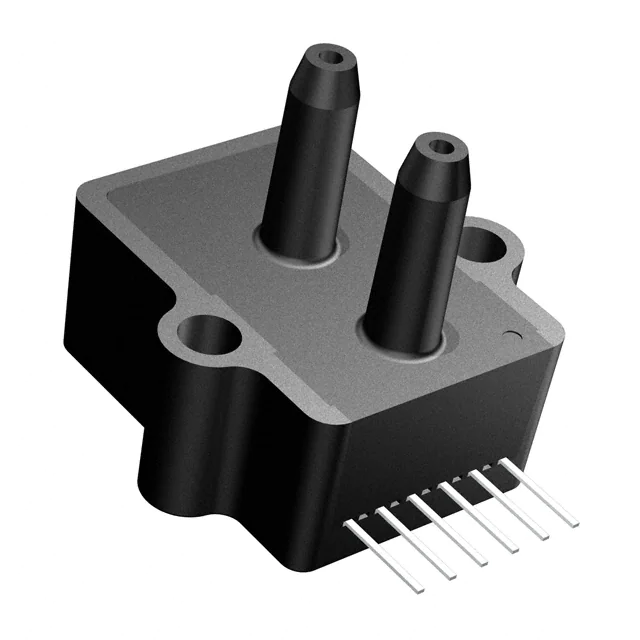
Enhanced Digital Output Sensors
•
•
•
•
Medical Instrumentation
Environmental Controls
HVAC
Meteorology
General Description
The Digital Output pressure sensors are based upon a proprietary surface mapping technology to produce a fully digital
output that virtually eliminates all repeatable errors over temperature and pressure. This series provides a 12 bit digital
serial output (14 bit in High Resolution Mode) with superior offset, span and linearity characteristics. The output is SPI and
MICROWIRE/PLUS® compatible as well as fully compatible with the All Sensors GA142 Series sensors.
In addition to synchronous communications, the Digital Output pressure sensors incorporates a bi-directional, TTL level,
asynchronous serial interfaces mode (hardware selectable 9,600 or 19,200 baud). This mode includes a command set that
allows the host to interrogate the sensor for model information, pressure range, serial number, pressure units and
conversion factor. The command set also allows the host to select a high resolution output mode, make minor adjustments
to offset and has an addressable feature that alows multiple sensors to be tied to the same interface buss.
This series is intended for use with non-corrosive, non-ionic working fluids such as air, dry gases and the like. All signals
are 5V TTL/CMOS compatible.
Physical Dimensions
0.25
(6.4)
Pin Descriptions
Pin Size
0.010 x 0.020
(0.25 x 0.50)
Pin 1 2 3 4 5 6
0.174 to 0.190
(4.4 to 4.8)
0.21
(5.3)
1
A
1.08
(27.4)
0.63
(16.0)
0.48
(12.2)
0.55
(14.0)
NOTES:
1) Dimensions in inches (millimeters)
0.80
(20.3)
Data/SI
Data output for synchronous
mode. Serial in for asynchronous mode.
3
Clock/SO
Clock output for synchronous
mode. Serial out for asynchronous mode.
4
Ready/Mode Ready output for synchronous
mode. Selects asynchronous
mode when held low during
reset.
5
Convert/BR
Convert input for synchronous
mode. Selects one of two
baud rates for asynchronous
mode (low=9,600,
high=19,200).
6
Ground
Ground for power and signals
0.414
(10.5)
0.85
(21.6)
DS-0012 Rev A
Description
+5V power supply input
2
B
1.10
(27.9)
All Sensors
Pin Label
1 Vcc
0.10 Typical
(2.54)
0 1
e www.allsensors.com
Applications
f 408 225 2079
5” H2O to 100psi Pressure Ranges
All Combined Errors Over Temperature Less Than 0.1%, Typical
Wide -20 to 85°C Compensated Temperature Range
Electrically Compatible to All Sensors GA142 Series
Enhanced Dual Serial Interface Mode
a 16035 Vineyard Blvd. Morgan Hill, CA 95037 p 408 225 4314
•
•
•
•
•
all sensors
Features
�Absolute Maximum Ratings
Environmental Specifications
Supply Voltage (Vcc)
7Vdc
Voltage on Any Pin with Respect to Gnd
Operating Voltage
-0.6 to Vcc+0.6V
Common-mode pressure
Compensated Temperature
50 psig
Lead Temperature (soldering 2-4 sec.)
+4.75Vdc to +5.25Vdc
250°C
-20° C to +85° C
Operating Temperature
-25 to +90° C
Storage Temperature
-40 to 125° C
Humidity Limits
0 to 95% RH
(non condensing)
Standard Pressure Ranges
(4)
Proof Pressure
Burst Pressure
5
1
200 inH2O
300 inH2O
inH2O
10
1
200 inH2O
300 inH2O
-1 to 1
PSI
1
1
200 inH2O
300 inH2O
-5 to 5
PSI
5
1
10 PSI
30 PSI
15 PSI-D-DO
-15 to 15
PSI
15
1
60 PSI
120 PSI
15 PSI-A-DO
0 to 15
PSIA
15
2
60 PSI
120 PSI
-30 to 30
PSI
30
2
90 PSI
150 PSI
0 to 30
PSIA
30
2
90 PSI
150 PSI
-100 to 100
PSI
100
2
200 PSI
250 PSI
0 to 100
PSIA
100
2
200 PSI
250 PSI
Part Number
Operating Pressure
Units
-5 to 5
inH2O
-10 to 10
1 PSI-D-DO
5 PSI-D-DO
5 INCH-D-DO
10 INCH-D-DO
30 PSI-D-DO
30 PSI-A-DO
100 PSI-D-DO
100 PSI-A-DO
FSO
(2)
Digital Span
General Performance Characteristics (All Models)
Parameter
(1)
Minimum
Nominal
Maximum
Units
12
--
--
Bit
Conversion Speed
--
8
16
mS
Supply Current
--
8
12
mA
Minimum
Nominal
Maximum
Units
--
0.25
0.5
%FSO
Long Term Drift (one year)
--
--
0.5
%FSO
Offset Position Sensitivity (1g)
--
--
0.05
%FSO
--
--
0.25
%FSO
Resolution
Performance Characteristics for 5 INCH-D-DO
Parameter
(1)
Overall Accuracy
(5)
Offset Warm-up Shift
(3)
Performance Characteristics for 10 INCH-D-DO and 1 PSI-D-DO
Parameter
(1)
Minimum
Nominal
Maximum
Units
--
0.25
0.5
%FSO
Long Term Drift (one year)
--
--
0.5
%FSO
Offset Position Sensitivity (1g)
--
--
0.03
%FSO
--
--
0.25
%FSO
Overall Accuracy
(5)
Offset Warm-up Shift
0 2
(3)
Digital Output Pressure Sensors
�Overall Accuracy
Minimum
Nominal
Maximum
Units
--
0.10
0.25
%FSO
--
--
0.25
%FSO
(5)
Long Term Drift (one year)
Specification Notes
NOTE 1:
UNLESS OTHERWISE SPECIFIED, ALL PARAMETERS ARE MEASURED AT 5.0 VOLT SUPPLY, POSITIVE PRESSURE APPLIED TO PORT B.
NOTE 2: THE DIGITAL OUTPUT IS A 16 BIT SIGNED BINARY OUTPUT IN A TWO’S COMPLIMENT FORMAT. T HE APPLIED PRESSURE IS COMPUTED USING THE PRESSURE
CONVERSION TABLE (BELOW). THE MODE COLUMN IDENTIFIES THE RESOLUTION OPERATING MODE OF THE DEVICE (A = STANDARD RESOLUTION, B =
HIGH RESOLUTION). FSO AND UNITS ARE SHOWN FOR EACH MODEL.
NOTE 3: SHIFT IS WITHIN THE FIRST HOUR OF EXCITATION APPLIED TO THE DEVICE.
NOTE 4: DIGITAL SPAN IS DEPENDENT ON THE RESOLUTION OPERATING MODE. REFER TO THE DIGITAL SPAN TABLE (BELOW) TO IDENTIFY THE DIGITAL SPAN OF THE
SPECIFIC MODEL. IN THE EVENT OF AN OVER-PRESSURE OR UNDER-PRESSURE CONDITION, THE DIGITAL OUTPUT WILL ONE COUNT HIGHER OR ONE COUNT
LOWER (RESPECTIVELY) TO THE LISTED DIGITAL SPAN TO INDICATE THE CONDITION.
NOTE 5: O VERALL ACCURACY INCLUDES THE COMBINED EFFECTS OF OFFSET AND SPAN SHIFTS OVER TEMPERATURE, LINEARITY, HYSTERESIS, AND OFFSET AND SPAN
CALIBRATION .
Synchronous Timing Diagram (Note: Asynchronous mode timing is per RS-232. To use RS-232 requires the Maxim MA232
interface circuit for proper voltage level compatibility.)
READY [Output]
t1
t10
t2
t2
e www.allsensors.com
Parameter (1)
all sensors
Performance Characteristics for 5 PSI-D-DO through 100 PSI-x-DO
f 408 225 2079
CONVERT [Input]
t3
t4
t8
t9
t5
CLOCK [Output]
t6
DATA [Output]
Bit
15
MSB
Ref
t1
t2
t3
t4
t5
Parameter
Conversion Time
Ready to Convert
Convert to Clock
Clock Period
Clock High Time
Min
-0
24
---
Typ
8
-32
24
12
Bit
14
Max
16
-39
---
Bit
13
Bit
12
Bit
11
Bit
10
Units
msec
usec
usec
usec
usec
Bit
9
Bit
8
Ref
t6
t7
t8
t9
t10
Bit
7
Bit
6
Bit
5
Parameter
Data Setup Time
Data Hold Time
Interbyte Delay
Clock to Ready
Data Transmission
Bit
4
Bit
3
Min
------
Bit
2
Typ
3
3
70
14
476
Bit
1
Bit
0
LSB
Max
------
Units
usec
usec
usec
usec
usec
Typical Configurations
Synchronous Communications
Asynchronous Communications
Typical synchronous communications
Typical asynchronous communications
configuration (compatible with All
configuration. The Mode pin is
Sensors GA142 Series Digital Output
interrogated at power up and if tied
Sensors).
low, will cause the sensor to enter
Sensor
Host
System
(1)
Clock/SO
Data/SI
Convert/BR
Ready/Mode
asynchronous communications mode.
Host
System
Sensor
Clock/SO
Data/SI
Convert/BR
Ready/Mode
All Sensors
This mode supports multiple sensors by
addressable commands. The Convert/
BR pin then serves to select one of two
available baud rates.
DS-0012 Rev A
Sensor
(n)
Clock/SO
Data/SI
Convert/BR
Ready/Mode
a 16035 Vineyard Blvd. Morgan Hill, CA 95037 p 408 225 4314
t7
�Command Summary Table:
Command
Description
Response
RA
Read Accuracy String
RA=[Accuracy String]
RC
Read Captured Pressure
RC=[hhhh][eeee]
RH
Read High Resolution Pressure
RH=[hhhh][eeee]
RL
Read Low Resolution Pressure
RL[llll][eeee]
RM
Read Model
RM=[Model String]
RR
Read Pressure Range
RR=[pressure Range String]
RS
Read Serial Number
RS=[S/N String]
RT
Read Temperature
RT=[Temperature Range String]
U[S/N String][Command]
Unique Command
For Matching S/N
U[S/N String],sp>[Response String]
For Non-matching S/N {null}
WC
Capture Pressure
{null}
Notations:
indicates a single ascii character
[] indicates an ascii string
{} text within the braces describes the response (this is essentially a comment)
16-Mar-03
“” text within quotes represents a literal ascii text string
0 4
Definitions:
Term
Name
Description
Carriage Return
ascii Carrage Return. This is a command/response delimiter
Space
ascii Space Character
[Accuracy String]
Accuracy String
Part accuracy string. Given in % full scale output.
Example: 0.250 %FSO
Notes:
1.) There is a space between the numeric accuracy “0.250”
and units “%FSO.”
2.) FSO stands for Full Scale Output (full scale output is
determined by the Pressure Range String.)
[hhhh]
High Resolution Output
This is a four character ascii string representing a
hexidecimal value.
Example: 3F7C
Represents an output count of 16,252
Note: the output is forced to “8000” upon an error.
except error bit 8, see error bit codes.
[llll]
Low Resolution Output
This is a four character ascii string representing a
hexidecimal value.
Example: 1D58
Represents an output count of 7,512
Note: the output is forced to “8000” upon an error.
except error bit 8, see error bit codes.
[Model String]
Model String
Part Model as given in the data sheet (also order number.)
The general model syntax is
[Full Scale Pressure][Pressure Units]-[Pressure Model]-DO
Example: 100 PSI-D-DO
Where:
Full Scale Pressure=100
Pressure Units=PSI (inH2O, mbar or mmHg available)
DO represents Digital Output
Notes:
1.) Exception to this syntax is the Barometer.
2.) Custom models may be different.
Digital Output Pressure Sensors
�[Response String]
A Fully Formed Response String
Example: “RL=1E430000
[S/N String]
Serial Number String
YMDD-NN-BSPP (12 character String)
Where:
Y : Year (0~9)
M : Month (A~M, excluding I)
DD: Day of Month
NN: Lot (lot sequence for a given day)
B : Lot Batch# (A~Z)
S : Test Oven Slot# (1~5)
P : Position on Slot (1~15)
Example: 3D23-03-A103
Month Codes
January : A
February : B
March
:C
April
:D
May
:E
June
:F
July
:G
August : H
September : J
October : K
November : L
December : M
April 23, 2003
3rd lot of the day
Batch A, Slot 1, Position 03
This allows traceability to original test data
[Temperature Range String]
Temperature Range String
This is the compensated temperature range of the part.
Syntax: [low limit][high limit]”C”
Example: -20 to 85 C
-40 to 125 C and custom ranges also available.
[eeee]
Error Codes
The error codes are bits packed within a double byte.
The four character string is an ascii hex expression.
The error code bits are:
Bit 0 : Part not factory compensated
Bit 1 : Tdex Overflow
Bit 2 : Tdex Over-range
Bit 3 : Pdex Overflow
Bit 4 : Pdex Over-range
Bit 5 : PWL Overflow
Bit 6 : Scale Overflow
Bit 7 : High Resolution Overflow
Bit 8 : Pressure Output Limited to Specific Value
Bits 9 through 15 : Reserved
Example: 0100
Represents erro bit 8 set and the Pressure Output Limited
Notes:
Bit 0 : This should not appear if the part has been calibrated
Bits 1 thru 7 : indicate computational error when compensated
Bit 8: indicates that the pressure applied to the part exceeds the
range of the part and is limit to either the high or low limit
{null}
Null Response
No response from the part. In the event of a serial number
mismatch the part will not respond (to avoid buss contention.)
All Sensors reserves the right to make changes to any products herein. All Sensors does not assume any liability arising out of the application or use of any product or circuit
described herein, neither does it convey any license under its patent rights nor the rights of others.
® MICROWIRE/PLUS
IS A REGISTERED TRADEMARK OF
All Sensors
NATIONAL SEMICONDUCTOR.
DS-0012 Rev A
all sensors
This is the compensated pressure range of the part.
Syntax: [low limit]”to”[high limit][units}[mode]
Esample: 20 to 32 mmHgA
Where:
Low limit = 20
High limit = 32
Units = mmHg
Mode = A (absolute pressure) (D differential and G gage
pressure also available.)
e www.allsensors.com
Description
Pressure Range String
f 408 225 2079
Name
[Pressure Range String]
a 16035 Vineyard Blvd. Morgan Hill, CA 95037 p 408 225 4314
Definitions:
Term
�
很抱歉,暂时无法提供与“5 PSI-D-DO”相匹配的价格&库存,您可以联系我们找货
免费人工找货