BOARD/WIRE-TO-BOARD
CONNECTORS
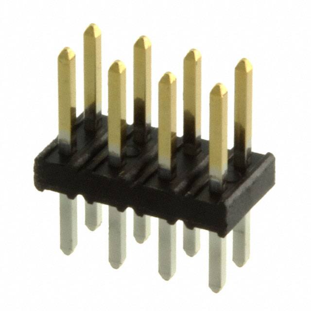
MINITEK® UNSHROUDED
VERTICAL HEADERS
�MINITEK® UNSHROUDED VERTICAL
HEADERS
TECHNICAL INFORMATION
MATERIALS
SPECIFICATIONS
• Housing: High temperature, black thermoplastic
•
File no. E66906
• Flammability rating: UL94V-0
•
File no. LR46923
• Pin: Phosphor-bronze
• Product drawing: 57102 or 57202
• Plating: Gold/GXT over 1.27μm (50μin.) nickel
• Product specification: DPS-12-011 and GS-12-163
ELECTRICAL PERFORMANCE
• Tape and reel packaging data: TA-884
• Current rating: 3A continuous
APPROVALS AND CERTIFICATIONS
• Insulation resistance: 1 x 10⁵MΩ min.
• This product is RoHS compatible according to the
European Union Directive 2002/95/IEC
• Contact resistance: 25mΩ max.
• Dielectric withstanding voltage: 650V
PACKAGING
• Voltage rating: 200V
• Standard: TMT in tubes (04 to 06 pos. packed in box)
ENVIRONMENTAL PERFORMANCE
• SMT in Tape-and-reel
• Operating temperature range: -55°C to +125°C
• Optional: SMT in tubes
PROCESSING INFORMATION
MECHANICAL PERFORMANCE
• Compatible
�
with wave, vapor-phase, and IR reflow
soldering processes
• Mating cycles (durability): 100
TYPICAL APPLICATIONS
For more information,
please contact: Communications@fci.com
or visit us at www.fci.com
Disclaimer
Please note that the above information is subject to change without notice.
�MINITEK® UNSHROUDED VERTICAL
HEADERS
PART NUMBERS
CORE RANGE
57202
G
52
XXALF
XX = 02, 03, 04, 05, 06, 08, 10
5
7
LEAD
0
2
PLATING
PIN
STYLE
POSITIONS
PER ROW
PACKAGING
Through Mount (TMT)
1
Through Mount (TMT)
02 to 25
Surface Mount (SMT)
2
Surface Mount (SMT)
02 to 25
LF
0.76μm (30μin.), gold/GXT on mating area,
2-6μm (79-237μin.) tin on solder side
G
Tube without cap (TMT)
U
F
Tape-and-reel with cap
(SMT)
A
Gold flash on mating area, 2-6μm
(79-237μin.) tin on solder side
Through Mount
Surface Mount
Pin Style
Mating Side
(mm)
Solder Side
(mm)
OAL
(mm)
Pin Style
Mating Side (mm)
2.00
51
4.00
2.50
8.00
06
4.00
52
4.00
3.00
8.50
08
PRODUCT
Recommended PCB Layouts
Dimension in mm
For more information,
please contact: Communications@fci.com
or visit us at www.fci.com
Disclaimer
Disclaimer
Please note that the above information is subject to change without notice.
�BOARD/WIRE-TO-BOARD
CONNECTORS
MINITEK® UNSHROUDED
RIGHT ANGLE HEADERS
FEATURES & BENEFITS
• High temperature plastic
• Selective plating
�MINITEK® UNSHROUDED
RIGHT ANGLE HEADERS
TECHNICAL INFORMATION
MATERIALS
SPECIFICATIONS
• Housing: High temperature, black thermoplastic
•
File no. E66906
• Flammability rating: UL94V-0
•
File no. LR46923
• Pin: Phosphor-bronze
• Product drawing: 98423
• Plating: Gold/GXT over 1.27μm (50μin.) nickel
• Product specification: DPS-12-011 and GS-12-163
ELECTRICAL PERFORMANCE
APPROVALS AND CERTIFICATIONS
• Current rating: 3A continuous
• This
�
product is RoHS compatible according
to the European Union Directive 2002/95/IEC
• Insulation resistance: 1 x 10⁵MΩ min.
• Contact resistance: 25Ωm max.
PACKAGING
• Dielectric withstanding voltage: 650V
• Tubes (04 to 06 pos. packed in box)
• Voltage rating: 200V
PROCESSING INFORMATION
ENVIRONMENTAL
• Compatible
�
with wave, vapor-phase, and IR reflow
soldering processes
• Operating temperature range: -55°C to +125°C
MECHANICAL PERFORMANCE
• Mating cycles (durability): 100
TYPICAL APPLICATIONS
For
Formore
more information,
information,
please
please contact:
contact: Communications@fci.com
Communications@fci.com
or
orvisit
visit us
us at
at www.fci.com
www.fci.com
Disclaimer
Disclaimer
Please
Pleasenote
notethat
thatthe
theabove
aboveinformation
informationisissubject
subjectto
tochange
changewithout
withoutnotice.
notice.
�MINITEK® UNSHROUDED
RIGHT ANGLE HEADERS
PART NUMBERS
9
8
4
2
3
PLATING
61
0.76μm (30μin.), gold/GXT on mating area,
2-6μm (79-237μin.) tin on solder side
G
Gold flash on mating area, 2-6μm
(79-237μin.) tin on solder side
F
POSITIONS
PER ROW
U
LF
02 to 25
PRODUCT
Recommended PCB Layouts
Dimension in mm
For more information,
please contact: Communications@fci.com
or visit us at www.fci.com
Disclaimer
Please note that the above information is subject to change without notice.
�BOARD/ WIRE-TO-BOARD
CONNECTORS
MINITEK® UNSHROUDED
HEADERS, PIN-IN-PASTE
�MINITEK® UNSHROUDED
HEADERS, PIN-IN-PASTE
TECHNICAL INFORMATION
MATERIALS
SPECIFICATIONS
• Housing: High temperature, black thermoplastic
•
File no. E66906
• Flammability rating: UL94V-0
•
File no. LR46923
• Pin: Phosphor-bronze
• Product drawing: By 8-digit base part number
• Plating: Gold/GXT over 1.27μm (50μin.) nickel
• Product specification: DPS-12-011 and GS-12-163
ELECTRICAL PERFORMANCE
• Application specification: TA-895
• Reflow profile: TA-842
• Current rating: 3A continuous
• Insulation resistance: 1 x 10⁵MΩ min
PACKAGING
• Contact resistance: 25Ωm max.
• Tubes (04 to 06 pos. packed in box)
• Dielectric withstanding voltage: 650V
• Tape-on-reel with pick up cap
• Voltage rating: 200V
PROCESSING INFORMATION
ENVIRONMENTAL
• Compatible
�
with wave, vapor-phase, and IR reflow
soldering processes
• Operating temperature range: -55°C to +125°C
MECHANICAL PERFORMANCE
• Mating cycles (durability): 100
TYPICAL APPLICATIONS
For more information,
please contact: Communications@fci.com
or visit us at www.fci.com
Disclaimer
Please note that the above information is subject to change without notice.
�MINITEK® UNSHROUDED
HEADERS, PIN-IN-PASTE
PART NUMBERS
8-DIGIT BASE
PART NUMBER
PLATING
Vertical
10075024
Right angle
10072353
PIN STYLE
POSITIONS
PER ROW
PACKAGING
LF
02 to 25
0.76μm (30μin.), gold/GXT on mating area,
2-6μm (79-237μin.) tin on solder side
G
Mating Side
(mm)
Solder Side
(mm)
Pin Style
Tube without cap
from 04 to 25 pos.
U
Gold flash on mating area, 2-6μm
(79-237μin.) tin on solder side
F
4.00
2.00
01
Tape, availibilty on
request
A
PRODUCT
10075024 Vertical
10072353 Right angle
Recommended PCB Layouts
Dimension in mm
For more information,
please contact: Communications@fci.com
or visit us at www.fci.com
Disclaimer
Please note that the above information is subject to change without notice.
�BOARD/WIRE-TO-BOARD
CONNECTORS
MINITEK® UNSHROUDED
STACKING HEADERS
FEATURES & BENEFITS
• Wide variety of stack heights in 0.13mm increments
• �Custom sizes to meet your specific design requirements
�MINITEK® UNSHROUDED
STACKING HEADERS
TECHNICAL INFORMATION
MATERIALS
SPECIFICATIONS
• Housing: High temperature, black thermoplastic
•
File no. E66906
• Flammability rating: UL94V-0
•
File no. LR46923
• Pin: Phosphor-bronze
• Product drawing: 59112, 59132, or 59202
• Plating: Gold over 1.27μm (50μin.) nickel
• Product specification: DPS-12-011
ELECTRICAL PERFORMANCE
APPROVALS AND CERTIFICATIONS
• Current rating: 2A continuous
• This
�
product is RoHS compatible according
to the European Union Directive 2002/95/IEC
• Insulation resistance: 1 x 10⁵MΩ min.
• Contact resistance: 25Ωm max.
PACKAGING
• Dielectric withstanding voltage: 650V
• Standard: In bags
• Voltage rating: 200V
PROCESSING INFORMATION
ENVIRONMENTAL
• Compatible
�
with wave, vapor-phase, and IR reflow
soldering processes
• Operating temperature range: -55°C to +125°C
MECHANICAL PERFORMANCE
• Mating cycles (durability): 100
TYPICAL APPLICATIONS
For
Formore
more information,
information,
please
please contact:
contact: Communications@fci.com
Communications@fci.com
or
orvisit
visit us
us at
at www.fci.com
www.fci.com
Disclaimer
Disclaimer
Please
Pleasenote
notethat
thatthe
theabove
aboveinformation
informationisissubject
subjectto
tochange
changewithout
withoutnotice.
notice.
�MINITEK® UNSHROUDED
STACKING HEADERS
PART NUMBERS
Compile your own part number using custom dimensions (Please allow for initial setup on our system)
5
9
LEAD
SOLDER
SIDE OPTION
Through Mount (TMT)
1
Surface Mount (SMT)
2
2.50
1
3.00
3
SMT
0
2
PLATING
0.76μm (30μin.)
gold on mating
side, tin on
solder side
T
PIN
STYLE
POSITIONS
PER ROW
Overall Length (OAL)
STACK
HEIGHT
Pin Style
(TMT) mm
(SMT) mm
8.20
6.53
22
9.55
7.87
24
10.19
8.51
26
11.79
10.11
28
13.54
11.86
30
14.10
12.42
32
15.60
13.92
34
17.09
15.42
36
19.08
17.40
38
21.08
19.41
40
LF
TMT
02 to 25
SMT
02 to 25
XXX = mm
Specify mm
(e.g., 037 = 03.7mm)
in 0.1mm increments
PRODUCT
The board spacing
is the stack height of this header,
plus the height of the receptacle
(see application drawings on
opposite page)
Recommended PCB layouts
Dimension in mm
For more information,
please contact: Communications@fci.com
or visit us at www.fci.com
Disclaimer
Please note that the above information is subject to change without notice.
�BOARD/ WIRE-TO-BOARD
CONNECTORS
MINITEK® VERTICAL RECEPTACLES
FEATURES & BENEFITS
• Two housing heights: 2.30mm, 4.50mm
• ��Dual-beam contact design for highly reliable
electrical performances
�MINITEK® VERTICAL RECEPTACLES
TECHNICAL INFORMATION
MATERIALS
APPROVALS AND CERTIFICATIONS
• Housing: High temperature, black thermoplastic
• This
�
product is RoHS compatible according
to the European Union Directive 2002/95/IEC
• Flammability rating: UL94V-0
PACKAGING
• Contact: Phosphor-bronze
• Beryllium-copper-63453
• Standard:
• TMT in tubes
• SMT in tape-and-reel
• Plating: Gold over 1.27μm (50μin.) nickel
ELECTRICAL PERFORMANCE
• Optional: Tubes (SMT)
• Current rating: 2A continuous
PROCESSING INFORMATION
• Insulation resistance: 1 x 10⁵MΩ min.
• Compatible
�
with wave, vapor-phase, and IR reflow
soldering processes
• Contact resistance:
• 20mΩ
• 25mΩ - 63453
INSERTION DEPTH
• Dielectric withstanding voltage: 650V
• ��4.50mm height: 3.00mm min. to 4.30mm max.
[provides .381mm wipe]
• Voltage rating: 200V
• �2.30mm height – top entry: 1.30mm min. to 2.20mm max.
[provides .381mm wipe]
ENVIRONMENTAL
• Operating temperature range: -55°C to +125°C
MECHANICAL PERFORMANCE
• �Mating cycles (durability):
• 25
• 100 - 63453
• �2.30mm height – bottom entry: 1.40mm min. to 2.20mm
max. [provides .381mm wipe] plus board thickness
TYPICAL APPLICATIONS
• �Contact retention to housing:
• 2.20 N (227gf) min.
• 4.90 N (500gf) min. – 63453
• �Insertion force per contact:
•� 1.80 N (184gf) max.
• 1.95 N (200gf) – 63453
• �Withdrawal force per contact:
• 0.20 N (20gf) min.
SPECIFICATIONS
•
File no. E66906
•
File no. LR46923
• Product drawing: By 5-digit base part number
• Product specification:
• GS-12-008
• DPS-12-011 - for 63453
For more information,
please contact: Communications@fci.com
or visit us at www.fci.com
Disclaimer
Please note that the above information is subject to change without notice.
�MINITEK® VERTICAL RECEPTACLES
PART NUMBERS
CORE RANGE
55510
1XXTRLF
XX = 04, 06, 08, 10, 12, 16, 20
5-DIGIT BASE
PART NUMBER
1
Through Mount (TMT)
Height
Entry
4.50
Top
TOTAL POSITIONS
Part
Number
63453
PACKAGING
0.76μm (30μin.),
gold on mating area,
2-6μm (79-237μin.)
tin on solder side
1
LF
Top Entry
04 to 50
Tubes (TMT)
- (dash)
Bottom Entry
04 to 30
Tape-andreel(SMT)
TR
Surface Mount (SMT)
4.50
Top
55510
2.30
Top
55508
2.30
Bottom
91596
PRODUCT
P/N 63453
Top Entry
P/N 55510
Bottom Entry
P/N 55508
Recommended PCB layouts
Dimension in mm
For more information,
please contact: Communications@fci.com
or visit us at www.fci.com
Disclaimer
Please note that the above information is subject to change without notice.
�BOARD/WIRE-TO-BOARD
CONNECTORS
MINITEK® SHUNTS
FEATURES & BENEFITS
• �Early entry, dual-beam contacts provide long wiping
action for reliable electrical contact
�MINITEK® SHUNTS
TECHNICAL INFORMATION
MATERIALS
SPECIFICATIONS
• Housing: High temperature, black thermoplastic
•
File no. E66906
• Flammability rating: UL94V-0
•
File no. LR46923
• Contact: Phosphor-bronze
• Product drawing: By 5-digit base part number
• Plating: Gold or tin over 1.27μm (50μin.) nickel
• Product specification: DPS-12-012
ELECTRICAL PERFORMANCE
APPROVALS AND CERTIFICATIONS
• Current rating: 1A continuous
• This
�
product is RoHS compatible according
to the European Union Directive 2002/95/IEC
• Insulation resistance: 1 x 10⁵MΩ min.
• Contact resistance: 25mΩ
PACKAGING
• Dielectric withstanding voltage: 650V
• Bags
• Voltage rating: 200V
PROCESSING INFORMATION
ENVIRONMENTAL
• Compatible
�
with wave, vapor-phase, and IR reflow
soldering processes
• Operating temperature range: -55°C to +125°C
INSERTION DEPTH
MECHANICAL PERFORMANCE
• 2.24mm min. [provides .381mm wipe]
• Mating cycles (durability): 50
• Insertion force per contact: 6.41 N (650gf) max.
• Withdrawal force per contact: 0.49 N (50gf) min.
TYPICAL APPLICATIONS
For
Formore
more information,
information,
please
please contact:
contact: Communications@fci.com
Communications@fci.com
or
orvisit
visit us
us at
at www.fci.com
www.fci.com
Disclaimer
Disclaimer
Please
Pleasenote
notethat
thatthe
theabove
aboveinformation
informationisissubject
subjectto
tochange
changewithout
withoutnotice.
notice.
�MINITEK® SHUNTS
PART NUMBERS
CORE RANGE
86730
8
101LF
6
7
3
0
PLATING
0.76μm (30μin.) gold on mating area,
2-6μm (79-237μin.) tin on solder side
1
Gold flash
0
0
1
LF
PRODUCTS
Dimension in mm
For more information,
please contact: Communications@fci.com
or visit us at www.fci.com
Disclaimer
Please note that the above information is subject to change without notice.
�BOARD/ WIRE-TO-BOARD
CONNECTORS
MINITEK® SHROUDED
VERTICAL HEADERS
FEATURES & BENEFITS
• 4-wall design prevents mis-mating
• ��Selective plating
• ��Co-planarity 0.1 (SMT)
�MINITEK® SHROUDED
VERTICAL HEADERS
TECHNICAL INFORMATION
MATERIALS
SPECIFICATIONS
• Housing: High temperature, cream-coloured thermoplastic
•
File no. E66906
• Flammability rating: UL94V-0
•
File no. LR46923
• Pin: Phosphor-bronze
• Product drawing: 98414 or 98424
• Plating: Gold/GXT over 1.27μm (50μin.) nickel
• Product specification: DPS-12-011 and GS-12-163
ELECTRICAL PERFORMANCE
• Tape and reel packaging data: TA-884
• Current rating: 2A continuous
APPROVALS AND CERTIFICATIONS
• Insulation resistance: 1 x 10⁵MΩ min.
• This
�
product is RoHS compatible according
to the European Union Directive 2002/95/IEC
• Contact resistance: �25mΩ max.
PACKAGING
• Dielectric withstanding voltage: 650V
ENVIRONMENTAL
• Standard:
• TMT in tubes (04 to 06 pos. packed in box)
• SMT in tape-and-reel
• Operating temperature range: -40°C to +125°C
• Optional: SMT in tubes (04 and 06 in box)
MECHANICAL PERFORMANCE
PROCESSING INFORMATION
• �Mating cycles (durability): 100
• Compatible
�
with wave, vapor-phase, and IR reflow
soldering processes
• Voltage rating: 200V
TYPICAL APPLICATIONS
For more information,
please contact: Communications@fci.com
or visit us at www.fci.com
Disclaimer
Please note that the above information is subject to change without notice.
�MINITEK® SHROUDED
VERTICAL HEADERS
PART NUMBERS
CORE RANGE
98424
G
52
XX
ALF
XX = 04, 06, 08, 10, 12, 16, 20
5-DIGIT BASE
PART NUMBER
PLATING
Through mount, double row
98414
Surface mount, double row
98424
PIN STYLE
TOTAL POSITIONS
04 to 50
0.76μm (30μin.), gold/GXT on mating area,
2-6μm (79-237μin.) tin on solder side
G
Gold flash on mating area,
2-6μm (79-237μin.) tin on solder side
F
PACKAGING
LF
Tube (TMT)
U
Tape-and-reel (SMT)
A
Surface Mount
Through Mount
Mating Side
(mm)
Pin Style
Mating
Side (mm)
Solder Side
(mm)
Pin
Style
4.00
52
4.00
2.50
06
PRODUCT
98414
Through mount
98424
Surface mount
Recommended PCB layouts
Dimension in mm
For more information,
please contact: Communications@fci.com
or visit us at www.fci.com
Disclaimer
Please note that the above information is subject to change without notice.
�BOARD/WIRE-TO-BOARD
CONNECTORS
MINITEK® SHROUDED
RIGHT ANGLE HEADERS
FEATURES & BENEFITS
• 4-wall design prevents mis-mating
• �Selective plating
�MINITEK® SHROUDED
RIGHT ANGLE HEADERS
TECHNICAL INFORMATION
MATERIALS
SPECIFICATIONS
• Housing: High temperature, cream-coloured thermoplastic
•
File no. E66906
• Flammability rating: UL94V-0
•
File no. LR46923
• Pin: Phosphor-bronze
• Product drawing: 98464
• Plating: Gold/GXT over 1.27μm (50μin.) nickel
• Product specification: DPS-12-011 and GS-12-163
ELECTRICAL PERFORMANCE
APPROVALS AND CERTIFICATIONS
• Current rating: 2A continuous
• This
�
product is RoHS compatible according
to the European Union Directive 2002/95/IEC
• Insulation resistance: 1 x 10⁵MΩ min.
• Contact resistance: 25mΩ max.
PACKAGING
• Dielectric withstanding voltage: 650V
• Standard: Tubes (04 pos. packed in box)
• Voltage rating: 200V
PROCESSING INFORMATION
ENVIRONMENTAL
• Compatible
�
with wave, vapor-phase, and IR reflow
soldering processes
• Operating temperature range: -40°C to +125°C
MECHANICAL PERFORMANCE
• Mating cycles (durability): 100
TYPICAL APPLICATIONS
For
Formore
more information,
information,
please
please contact:
contact: Communications@fci.com
Communications@fci.com
or
orvisit
visit us
us at
at www.fci.com
www.fci.com
Disclaimer
Disclaimer
Please
Pleasenote
notethat
thatthe
theabove
aboveinformation
informationisissubject
subjectto
tochange
changewithout
withoutnotice.
notice.
�MINITEK® SHROUDED
RIGHT ANGLE HEADERS
PART NUMBERS
9
8
4
6
4
PLATING
61
0.76μm (30μin.) gold/GXT on mating area,
2-6μm (79-237μin.) tin on solder side
G
Gold flash on mating area,
2-6μm (79-237μin.) tin on solder side
F
TOTAL
POSTION
U
LF
04 to 50 (Double row)
PRODUCTS
Recommended PCB layouts
Dimension in mm
For more information,
please contact: Communications@fci.com
or visit us at www.fci.com
Disclaimer
Please note that the above information is subject to change without notice.
�BOARD/ WIRE-TO-BOARD
CONNECTORS
MINITEK® SHROUDED
HEADERS, PIN-IN-PASTE
�MINITEK® SHROUDED
HEADERS, PIN-IN-PASTE
TECHNICAL INFORMATION
MATERIALS
MECHANICAL PERFORMANCE
• Housing: High temperature, black thermoplastic
• �Latching retention force: 30 N min.
• Flammability rating: UL94V-0
SPECIFICATIONS
• Pin: Phosphor-bronze
•
File no. E66906
• Plating: Gold/GXT over 1.27μm (50μin.) nickel
•
File no. LR46923
ELECTRICAL PERFORMANCE
• Product drawing: 8-digit part number
• Current rating: 3A continuous
• Product specification: DPS-12-011 and GS-12-163
• Insulation resistance: 1 x 10⁵MΩ min.
• Application specification: TA-895
• Contact resistance: �25mΩ max.
• Reflow prpfile: TA-842
• Dielectric withstanding voltage: 650V
PACKAGING
• Voltage rating: 200V
• Tubes (04 pos. packed in box)
ENVIRONMENTAL
• Tape-on-reel with pick up cap
• Operating temperature range: -55°C to +125°C
PROCESSING INFORMATION
• Compatible
�
with wave, vapor-phase, and IR reflow
soldering processes
TYPICAL APPLICATIONS
For more information,
please contact: Communications@fci.com
or visit us at www.fci.com
Disclaimer
Please note that the above information is subject to change without notice.
�MINITEK® SHROUDED
HEADERS, PIN-IN-PASTE
PART NUMBERS
8-DIGIT BASE
PART NUMBER
PLATING
Vertical
10075025
Right angle
10072354
PIN STYLE
TOTAL POSITIONS
PACKAGING
04 to 50 (Double row)
0.76μm (30μin.), gold/GXT on mating area,
2-6μm (79-237μin.) tin on solder side
G
Mating Side
(length)
Solder Side
(length)
Pin
Style
Gold flash on mating area,
2-6μm (79-237μin.) tin on solder side
F
4.00
2.00
01
LF
Tube without cap
from 04 to 25 pos.
U
Tape, availability
on request
A
PRODUCT
10075025
Vertical
10072354
Right angle
Recommended PCB layouts
Dimension in mm
For more information,
please contact: Communications@fci.com
or visit us at www.fci.com
Disclaimer
Please note that the above information is subject to change without notice.
�BOARD/WIRE-TO-BOARD
CONNECTORS
MINITEK® SHROUDED
HEADERS EJECT LATCH
FEATURES & BENEFITS
• Secure latching of cable connector
• Easy ejection when required
• Works with IDC connectors with or without strain relief
• Low profile
�MINITEK® SHROUDED
HEADERS, EJECT LATCH
TECHNICAL INFORMATION
MATERIALS
SPECIFICATIONS
• Housing: Body, cream-colored LCP, Latch black PA
•
File no. E66906
• Flammability rating: UL94V-0
•
File no. LR46923
• Pin: Phosphor-bronze
• Product drawing: 8-digit part number
• Plating: Gold/GXT over 1.27μm (50μin.) nickel
• Product specification: GS-12-469
ELECTRICAL PERFORMANCE
APPROVALS AND CERTIFICATIONS
• Current rating: 2A continuous
• This
�
product is RoHS compatible according
to the European Union Directive 2002/95/IEC
• Insulation resistance: 1 x 10⁵MΩ min.
• Contact resistance: 25mΩ max.
PACKAGING
• Dielectric withstanding voltage: 650V
• Standard: Tubes
• Voltage rating: 200V
PROCESSING INFORMATION
ENVIRONMENTAL
• Compatible
�
with wave, vapor-phase, and IR reflow
soldering processes
• Operating temperature range: -40°C to +125°C
MECHANICAL PERFORMANCE
• Latching retention force: 30 N min.
TYPICAL APPLICATIONS
With strain relief
standard latch
Without strain relief
low profile latch
For
Formore
more information,
information,
please
please contact:
contact: Communications@fci.com
Communications@fci.com
or
orvisit
visit us
us at
at www.fci.com
www.fci.com
Disclaimer
Disclaimer
Please
Pleasenote
notethat
thatthe
theabove
aboveinformation
informationisissubject
subjectto
tochange
changewithout
withoutnotice.
notice.
�MINITEK® SHROUDED
HEADERS, EJECT LATCH
PART NUMBERS
CORE RANGE
10078991
G
22
XX
U
LF
10078991
G
02
XX
U
LF
XX = 06, 08, 10, 12
8-DIGIT BASE
PART NUMBER
G
Vertical
TMT
10078991
Vertical
SMT
10078995
0.76μm (30μin.)
gold/GXT on
mating area
G
PIN STYLE
LATCH TYPE
TOTAL
POSITIONS
Standard latch
1
Low profile latch
2
PACKAGING
LF
6, 8, 10, 12, 14,
24, 30, 40, 44, 50
Solder Side
Style
Tube, for through mount
U
SMT
0
Tape-and-reel, SMT only*
A
2.50mm TMT
2
Tube with cap, SMT only
B
3.10mm TMT
3
* As available
PRODUCT
10078991
Vertical TMT
Recommended
PCB Layout
Low Profile Latch
10078995
Vertical SMT
Recommended
PCB Layout
Dimension in mm
For more information,
please contact: Communications@fci.com
or visit us at www.fci.com
Disclaimer
Please note that the above information is subject to change without notice.
�BOARD/ WIRE-TO-BOARD
CONNECTORS
MINITEK® CRIMP-TO-WIRE
HOUSINGS AND CONTACTS
FEATURES & BENEFITS
• �Dual-beam contact design for highly reliable
electrical performance
• ��Latching key assures proper alignment and friction retention
�MINITEK® CRIMP-TO-WIRE
HOUSING AND CONTACTS
TECHNICAL INFORMATION
MATERIALS
SPECIFICATIONS
• Housing: Black thermoplastic
•
File no. E66906
• Flammability rating: UL94V-0
•
File no. LR46923
• Contact: Phosphor-bronze
• Product drawing:
• 77138 or 77139 – Contact
• 69307, 90311 – Housing
• Plating: Gold or tin over 1.27μm (50μin.) nickel
ELECTRICAL PERFORMANCE
• Product specification: 110-036
• Current rating: 2A continuous
• Application specification: 100-006, TA-959
• Insulation resistance: 1 x 10 MΩ min.
APPROVALS AND CERTIFICATIONS
5
• Contact resistance: �20mΩ max.
• T� his product is RoHS compatible according to the European
Union Directive 2002/95/IEC
• Dielectric withstanding voltage: 650V
• Voltage rating: 200V
PACKAGING
ENVIRONMENTAL
• Reels - Contacts
• Operating temperature range: -40°C to +125°C
• Bags - Housings
MECHANICAL PERFORMANCE
PROCESSING INFORMATION
• Mating cycles (durability): 100
• Compatible
�
with wave, vapor-phase, and IR reflow
soldering processes
• Contact retention to housing: 7.83 N (800gf) min.
• Mating force per contact: 1.77 N (180gf) max.
INSERTION DEPTH
• Unmating force per contact: 0.20 N (20gf) min.
• �2.40mm min. to 3.30mm max. [provides .381mm wipe]
• 3.63mm
�
min. to 4.00mm max.
[provides .381mm wipe in housing]
TYPICAL APPLICATIONS
For more information,
please contact: Communications@fci.com
or visit us at www.fci.com
Disclaimer
Please note that the above information is subject to change without notice.
�MINITEK® CRIMP-TO-WIRE
HOUSING AND CONTACTS
PART NUMBERS
CORE RANGE
77138
101LF
10087010
0XXLF
XX = 04, 06, 08, 10, 12, 16, 20
CONTACTS
77138
PLATING
26 AWG to 30 AWG
0
1
LF
0.76μm (30μin.) gold on mating area
1
Gold flash
0
HOUSINGS
90311
0
TOTAL POSITIONS
LF
04 to 50 (Double row)
PRODUCT
CONTACTS
HOUSINGS
10087010
Dimension in mm
For more information,
please contact: Communications@fci.com
or visit us at www.fci.com
Disclaimer
Please note that the above information is subject to change without notice.
�BOARD/WIRE-TO-BOARD
CONNECTORS
MINITEK® CRIMP-TO-WIRE
ACTIVE LATCH HOUSINGS
FEATURES & BENEFITS
• �Latching rentention 15/25 N (depending on size)
due to latch alone
• �Latches with audible click
• � Mates with standard Minitek®headers
• �Latch can be released and parts unmated
�MINITEK® CRIMP-TO-WIRE
ACTIVE LATCH HOUSINGS
TECHNICAL INFORMATION
MATERIALS
SPECIFICATIONS
• Housing: Polyamide, black
•
File no. E66906
• Flammability rating: UL94V-0
•
File no. LR46923
ELECTRICAL PERFORMANCE
• Product drawing: By 8-digit part number
• Insulation resistance: 1 x 10⁵MΩ min.
• Product specification: GS-12-415
• Dielectric withstanding voltage: 500V
APPROVALS AND CERTIFICATIONS
ENVIRONMENTAL
• This
�
product is RoHS compatible according
to the European Union Directive 2002/95/IEC
• Operating temperature range: -55°C to +125°C
PACKAGING
MECHANICAL PERFORMANCE
• Latching retention force: 15 N min. (for 2x3 and 2x4 pos.)
• Standard: Plastic bags
• Latching retention force: 25 N min. (for 2x5 and 2x25 pos.)
TYPICAL APPLICATIONS
For
Formore
more information,
information,
please
please contact:
contact: Communications@fci.com
Communications@fci.com
or
orvisit
visit us
us at
at www.fci.com
www.fci.com
Disclaimer
Disclaimer
Please
Pleasenote
notethat
thatthe
theabove
aboveinformation
informationisissubject
subjectto
tochange
changewithout
withoutnotice.
notice.
�MINITEK® CRIMP-TO-WIRE
ACTIVE LATCH HOUSINGS
PART NUMBERS
CORE RANGE
77138
101LF
10073599
0XXLF
XX = 04, 08, 10, 12, 16, 20
CONTACTS
77138
PLATING
26 AWG to 30 AWG
0
1
LF
0.76μm (30μin.) gold on mating area
1
Gold flash
0
HOUSINGS
10073599
0
TOTAL POSITIONS
LF
06 to 50
PRODUCT
CONTACTS
HOUSINGS
Dimension in mm
For more information,
please contact: Communications@fci.com
or visit us at www.fci.com
Disclaimer
Please note that the above information is subject to change without notice.
�BOARD/ WIRE-TO-BOARD
CONNECTORS
MINITEK® IDC RECEPTACLE
FEATURES & BENEFITS
• �Early entry, single-beam contacts provide long wiping
action for reliable electrical contact
• Center key polarization and friction latch options
�MINITEK® IDC RECEPTACLE
TECHNICAL INFORMATION
MATERIALS
SPECIFICATIONS
• Housing: Black thermoplastic
•
File no. E66906
• Flammability rating: UL94V-0
•
File no. LR46923
• Contact: Phosphor-bronze
• Product drawing: �89947 or 89361
• Plating: Gold over 1.27μm (50μin.) nickel
• Product specification: BUS-12-115
ELECTRICAL PERFORMANCE
APPROVALS AND CERTIFICATIONS
• Current rating: 1A continuous
• Insulation resistance: 1 x 10⁵MΩ min.
• T� his product is RoHS compatible according to the European
Union Directive 2002/95/IEC
• Contact resistance: �30mΩ max.
PACKAGING
• Dielectric withstanding voltage: 650V
• Tubes
ENVIRONMENTAL
INSERTION DEPTH
• Operating temperature range: -40°C to +105°C
• 2.55mm
�
min. to 4.57mm max.
[provides .381mm wipe]
MECHANICAL PERFORMANCE
• Mating cycles (durability): 100
TYPICAL APPLICATIONS
For more information,
please contact: Communications@fci.com
or visit us at www.fci.com
Disclaimer
Please note that the above information is subject to change without notice.
�MINITEK® IDC RECEPTACLE
PART NUMBERS
CORE RANGE
89361
7XXLF
XX = 06, 08, 10, 12, 16, 20
5-DIGIT BASE
PART NUMBER
CENTER
KEY
0.76μm (30μin.) gold
89947
0.20μm (8μin.) gold
89361
TOTAL
POSITIONS
06 to 50
S
LF
Add optional S for
strain relief
Optional S
Standard
1
With center key and friction latching (available from 06 to 30 positions)
7
PRODUCT
Dimension in mm
For more information,
please contact: Communications@fci.com
or visit us at www.fci.com
Disclaimer
Please note that the above information is subject to change without notice.
�BASICS+
MORE OPTIONS
If you need someting more than the standard parts in this catalog, Basics+ has many more options to help you in your design
process. Here are just some examples.
• Locating pins on SMT headers
• Polarized (missing) positions
• Kinked legs
• Press-fit pins
• Add-on latches for headers
• Wide body headers
• Crimp-to-wire pin
• Printed housings
• Additional plating options
BWBMNT2MM1115EA4
• Pin-in-paste headers
For more information,
please contact: Communications@fci.com
or visit us at www.fci.com
Disclaimer
Please note that the above information is subject to change without notice.
�Mouser Electronics
Authorized Distributor
Click to View Pricing, Inventory, Delivery & Lifecycle Information:
FCI / Amphenol:
57102-G08-16 57102-S08-04 57202-G52-05A 59202-F40-10-153 57202-S52-16 59202-S36-25-114LF 61698302TRLF 69057-012TC 57102-G08-06 57102-F08-25 61698-302TR 57102-S06-05 58102-S61-13 57102-G0818LF 98423-F61-02LF 98423-F61-05LF 98423-F61-05ULF 98423-F61-06LF 98423-F61-06ULF 98423-F61-07LF
98423-F61-07ULF 98423-F61-10LF 98423-F61-10ULF 98423-F61-21LF 98423-F61-21ULF 98423-G61-03LF
98423-G61-08LF 98423-G61-08ULF 98423-G61-10LF 98423-G61-10ULF 98423-G61-16LF 98423-G61-16ULF
98423-G61-17LF 98423-G61-17ULF 98423-G61-18LF 98423-G61-18ULF 98423-S61-20ULF 57102-F06-04LF
57102-F06-04ULF 57102-F06-06LF 57102-F06-13LF 57102-F06-13ULF 57102-F06-15LF 57102-F06-15ULF 57102F06-22LF 57102-F08-02LF 57102-F08-03LF 57102-F08-04LF 57102-F08-04ULF 57102-F08-05LF 57102-F0805ULF 57102-F08-06LF 57102-F08-08LF 57102-F08-10LF 57102-F08-10ULF 57102-F08-11LF 57102-F08-12LF
57102-F08-16LF 57102-F08-17LF 57102-F08-18LF 57102-F08-19LF 57102-F08-20LF 57102-F08-21LF 57102-F0822LF 57102-F08-23LF 57102-F08-24LF 57102-G06-03LF 57102-G06-04LF 57102-G06-04ULF 57102-G06-08LF
57102-G06-08ULF 57102-G06-10LF 57102-G06-11LF 57102-G06-12LF 57102-G06-12ULF 57102-G06-22LF
57102-G06-22ULF 57102-G06-25LF 57102-G08-02LF 57102-G08-03LF 57102-G08-04LF 57102-G08-05LF 57102G08-08LF 57102-G08-09LF 57102-G08-10LF 57102-G08-12LF 57102-G08-13LF 57102-G08-13ULF 57102-G0815LF 57102-G08-16LF 57102-G08-17LF 57102-G08-19LF 57102-G08-22LF 57102-G08-24LF 57102-G08-25LF
57202-F51-02LF 57202-F51-03LF 57202-F51-04LF 57202-F51-06LF 57202-F51-06ULF
�


 工商网监
湘ICP备2023018690号
工商网监
湘ICP备2023018690号

