BergStik® 2.54mm
Unshrouded Headers
BergStik® 2.54mm pitch unshrouded headers provide Boardto-Board, Wire-to-Board and Cable-to-Board interconnect
solutions for all types of electronic equipment and devices.
www.fci.com/products/bergstik
�CONTENT PAGE
BERGSTIK® 2.54MM UNSHROUDED HEADERS
3
Overview
For Pin-in-Paste Processes
4-7
Vertical Headers Standard sizes
8-9
Vertical Headers Special sizes
10-11
Continuous Headers
12-13
Right Angle Headers Standard sizes
14-15
Right Angle Headers Special sizes
16-17
Stacking Headers
18-19
For more information,
please contact: Communications@fci.com
or visit us at www.fci.com
Disclaimer
Please note that the above information is subject to change without notice.
2
�BOARD/WIRE-TO-BOARD
CONNECTORS
BERGSTIK® 2.54MM
UNSHROUDED HEADERS
OVERVIEW
BergStik® 2.54mm unshrouded headers are available in
surface-mount (SMT), through-hole (THT), press-fit, stacking
and pin-in-paste (PIP) versions. Designed in single and double
row, they are available in straight or right angle options, from
2 to 72 positions.
Featuring a “breakaway” design, each connector can be cut or
broken to length to suit the application profile. The maximum
current rating is 3A per contact.
This product range is extended with BergStik® 2.54mm
unshrouded vertical headers in 0.25µm plating, available in
standard sizes. It offers an economical solution for various
applications. It is also specified up to 100 mating cycles.
BergStik® product range provides Board-to-Board, Wireto-Board and Cable-to-Board interconnect solutions for all
electronic equipment and devices.
FEATURES
BENEFITS
• High temperature thermoplastic material
• Reflow compatible
• Variable spacing height for stacking headers
• Cater to a wide range of applications
• Allow dual entry; mating from top or bottom
• Suitable for mezzanine application and gives more flexibility in
meeting different stack height requirements
• Blank 0.64mm square contacts presents 4 surfaces of
equal quality
• Can be used for wire wrapping
• Standoff design
• Allows cleaning to remove soldering contamination
• Duplex plating
• Cost-efficient
• Tin-lead plating in press-fit area
• Easy pin insertion onto PCB
• Retention legs option
• High retention force onto PCB
• Press-fit designed to fit 1.02mm diameter hole, solder-toboard product
• Same layout on THT and press-fit
• Meets DIN 41651 specification, HE13 and BT D2632
• Qualified product
www.fci.com/products/bergstik
3
�BOARD/WIRE-TO-BOARD
CONNECTORS
BERGSTIK® UNSHROUDED HEADERS
FOR PIN-IN-PASTE PROCESSES
Pin-in-Paste (PIP) technology allows the use of THT products in SMT manufacturing processes. THT connectors are automatically or
manually soldered to PCB, and soldered in the same operation as the SMT connectors. Mechanical strength is retained through THT leads.
This process is critical for applications in industrial and automotive markets.
PRODUCT
PLASTIC MATERIAL
BergStik® PIP headers are moulded in high temperature thermoplastic. The headers are able to withstand exposure to 260°C peak
temperature for 30 seconds maximum in a convection, infrared or vapor phase reflow oven.
HOUSING DESIGN
A special housing has been developed for the double row straight product. A row of higher standoffs has been placed in the longitudinal
center axis, between both rows of pins for a good solder paste deposit around the pin. Please follow the stencil design guidelines TA-894
and TA-897 on the following page in order to avoid solder paste deposit under the standoffs.
4
�BERGSTIK® UNSHROUDED HEADERS
FOR PIN-IN-PASTE PROCESSES
APPLICATION
FCI’s application guideline helps to achieve optimum performance for BergStik® PIP process.
STENCIL DESIGN
The stencil design is crucial for a good solder joint. It determines
the amount of paste and the position of the paste print on the
board. Each PCB hole has its own stencil aperture with enough
spacing in between to allow separate solder deposits. This prevents
solder robbing from one hole to another and ensures the correct
amount of solder paste for each hole. The print position is placed
asymmetrical to optimize the flow of molten solder paste.
PASTE APPLICATION
The amount of paste for each hole depends on the soldering process
parameters and the degree of hole filling. It is recommended to
apply the squeegee at a 45° angle. You can use a smaller angle for an
even greater degree of hole filling. The squeegee moves in parallel
with the shorter sides of the stencil apertures.
BOARD LAYOUT
Please use a hole of 1.00 +/– 0.05 mm for an optimum paste deposit.
For automatic pick-and place, lean towards the upper end of the
tolerance. Refer to TA-894 for further information.
www.fci.com/products/bergstik
5
�BERGSTIK® UNSHROUDED HEADERS
FOR PIN-IN-PASTE PROCESSES
TECHNICAL INFORMATION
MATERIALS
MECHANICAL PERFORMANCE
• Housing: PCT
• Retention Force: 8.8N min
• �Color: Black
SPECIFICATIONS
• �Flammability Rating: UL94V-O
• Pins: Copper Alloy
• �Plating: Selective Gold or GXT or full Tin over 1.2μm Nickel
•
•
File no. E66906
File no. LR46923
• ��Product Drawing: 10076801/ 10082201/ 10082202
ELECTRICAL PERFORMANCE
• Product Specification: BUS-12-019
• Current Rating: 3A per contact
APPROVALS AND CERTIFICATIONS
• �Insulation Resistance: 5000MΩ min.
• RoHS compliant according to the European Union Directive
2002/95/IEC
• Dielectric Withstanding Voltage: 1500V
ENVIRONMENTAL
• Operating Temperature: -65°C to +130°C
6
�BERGSTIK® UNSHROUDED HEADERS
FOR PIN-IN-PASTE PROCESSES
PART NUMBER SELECTOR
X
XX
XX
X
XX
PLATING
CODE
PIN STYLE
LENGTH*
TOTAL
POSITIONS
PACKAGING
OPTION
LEAD-FREE
XXXXXXXX
BASE PART
NUMBER
-
LF
Straight
Double row
10076801
0.76mm (30µin.) or GXT PdNi with
gold flash on contact area, tin on
solder side
1
Tin
4
Double row
04 to 72
Mating Solder Overall
Pin Style
5.84
2.50
10.8
01
6.75
2.50
11.5
02
Standard product = plastic bag
1
Tape reel with pick up cap
(contact FCI for availability)
4
*Other pin style are available upon request
XXXXXXXX
BASE PART
NUMBER
-
X
XX
XX
X
XX
PLATING
CODE
PIN STYLE
LENGTH*
TOTAL
POSITIONS
PACKAGING
OPTION
LEAD-FREE
LF
Right
Angle
Single row
10082201
Double row
10082202
0.76µm (30µin.) Gold or GXT on
contact area, tin on solder side
1
Tin
4
Single row
03 to 36
Double row
04 to 72
Mating Solder Pin Style
5.84
2.5
01
6.75
2.5
02
Standard product = plastic bag
1
Tape reel with pick up cap
(contact FCI for availability)
4
*Other pin style are available upon request
www.fci.com/products/bergstik
7
�BOARD/WIRE-TO-BOARD
CONNECTORS
BERGSTIK® UNSHROUDED
VERTICAL HEADERS STANDARD SIZES
APPLICATION
7.20mm
for increased
board density
PRODUCT
0.62 square pin
0.62 square pin
0.62 square pin
Recommended PCB Layouts
Dimensions in mm
8
�BERGSTIK® UNSHROUDED
VERTICAL HEADERS STANDARD SIZES
TECHNICAL INFORMATION
MATERIALS
SPECIFICATIONS
• Housing: High temperature thermoplastic, Black
•
File no. E66906
• Flammability Rating: UL94V-0
• �
File no. LR46923
• Pin: Phosphor-bronze
• Product Drawing: 77311/ 77313/ 98401/ 95278
• Plating: Gold or Tin over 1.27μm (50μin.) Nickel
• Product Specification: BUS-12-114
ELECTRICAL PERFORMANCE
• Tape and Reel Packaging Data: TA-840
• Current Rating: 3A per contact
APPROVALS AND CERTIFICATIONS
• Insulation Resistance: 5000MΩ min.
• Dielectric Withstanding Voltage: 1500V
• R
� oHS compatible according to the European Union Directive
2002/95/IEC
ENVIRONMENTAL
PACKAGING
• Operating Temperature: -65°C to +125°C
• Bags
MECHANICAL PERFORMANCE
• Optional: Tubes or tape-and-reel with pick-up cap (only
applicable for SMT pin style 01)
• Retention Force: 9N min.
PROCESSING INFORMATION
• Compatible with wave, vapor-phase, and (for SMT) IR reflow
soldering processes
• Recommended IR profile TA 842 for SMT
PART NUMBER SELECTOR
XXXXX
BASE PART
NUMBER
-
X
XX
X
XX
XX
PLATING
CODE
PIN STYLE
LENGTH
PACKAGING
OPTION
TOTAL
POSITIONS
LEAD-FREE
THT
LF
Packaging
Configuration
Option
Single row
77311
Plastic bag
THT
-
Double row
77313
Tape-and-reel with pick-up cap
SMT
A
Tube with pick-up cap
SMT
B
SMT
Single row
98401
Double row
95278
0.76µm (30µin.) Gold or GXT on
contact, tin on solder side
THT
1
0.38µm (15µin.) Gold or GXT on
contact area, tin on solder side
8
0.25µm (10µin.) Gold or GXT on
contact area, tin on solder side
5
Tin
4
SMT
Mating
Length
Solder
Overall
Pin
Style
5.84
2.41
10.80
01*
5.84
3.05
11.43
18*
5.84
3.42
11.80
02
Single row THT
02 to 36
6.60
2.66
11.82
27
Single row SMT
03 to 17
7.75
3.06
13.35
22
Double row THT
04 to 72
6.75
2.90
12.20
24*
Double row SMT
04 to 50
Double row SMT with pegs
08 to 50
*Most popular configurations
Mating
Pin Style
5.84
01
8.08
02
www.fci.com/products/bergstik
9
�BOARD/WIRE-TO-BOARD
CONNECTORS
BERGSTIK® UNSHROUDED
VERTICAL HEADERS SPECIAL SIZES
APPLICATION
PRODUCT
0.62 square pin
0.62 square pin
Recommended PCB Layouts
Dimensions in mm
10
�BERGSTIK® UNSHROUDED
VERTICAL HEADERS SPECIAL SIZES
TECHNICAL INFORMATION
MATERIALS
SPECIFICATIONS
• Housing: High temperature thermoplastic, Black
•
File no. E66906
• Flammability Rating: UL94V-0
• �
File no. LR46923
• Pin: Phosphor-bronze
• Product Drawing: 68000/ 67996
• Plating: Gold or Tin over 1.27μm (50μin.) Nickel
• Product Specification: BUS-12-114
ELECTRICAL PERFORMANCE
APPROVALS AND CERTIFICATIONS
• Current Rating: 3A per contact
• RoHS compatible according to the European Union Directive
2002/95/IEC
• Insulation Resistance: 5000MΩ min
• Dielectric Withstanding Voltage: 1500V
PACKAGING
ENVIRONMENTAL PERFORMANCE
• Bags
• Operating Temperature: -65°C to +125°C
• O
� ptional: Tubes or tape-and-reel with pick-up cap (only
applicable for SMT pin style 01)
MECHANICAL PERFORMANCE
PROCESSING INFORMATION
• Retention Force: 9N min.
• C
� ompatible with wave, vapor-phase, and IR reflow soldering
processes
• Retentive Leg Insertion Force: >44.48N max.
• Retentive Leg Board Retention: 2.22N
PART NUMBER SELECTOR
Customize your own part number using custom dimensions (Please allow for initial setup on our system)
XXXXX
BASE PART
NUMBER
-
X
XX
PLATING
CODE
TOTAL
POSITIONS
-
XXX
XXX
XX
MATING
DIMENSION
SOLDER SIDE
DIMENSION
LEAD-FREE
THT
Single row
68000
Single row
01 to 36
Double row
67996
Double row
01 to 72
0.76μm (30μin.) Gold or GXT
1
0.38μm (15μin.) Gold or GXT
2
Tin
4
In 0.1mm increments
e.g. 030 = 3.0mm
LF
In 0.1mm increments
e.g. 255 = 25.5mm
Note: 1. The total combined dimension for mating and solder side may not exceed 27mm
2. Standard packaging in bulk
3. Special packaging availability upon request
www.fci.com/products/bergstik
11
�BOARD/WIRE-TO-BOARD
CONNECTORS
BERGSTIK® UNSHROUDED
CONTINUOUS HEADERS
APPLICATION
PRODUCT
Recommended PCB Layouts
Dimension in mm
12
�BERGSTIK® UNSHROUDED
CONTINUOUS HEADERS
TECHNICAL INFORMATION
MATERIALS
SPECIFICATIONS
• Housing: High temperature thermoplastic, Black
•
File no. E66906
• Flammability Rating: UL94V-0
• �
File no. LR46923
• Pin: Phosphor-bronze
• Product Drawing: 54101/ 54102/ 77311/ 77313
• Plating: Gold or Tin over 1.27μm (50μin.) Nickel
• Product Specification: BUS-12-059
ELECTRICAL PERFORMANCE
APPROVALS AND CERTIFICATIONS
• Current Rating: 3A per contact
• R
� oHS compatible according to the European Union Directive
2002/95/IEC
• Insulation Resistance: 5000MΩ min
• Dielectric Withstanding Voltage: 1500V
PACKAGING
ENVIRONMENTAL PERFORMANCE
• Reel
• Operating Temperature: -65°C to +125°C
PROCESSING INFORMATION
MECHANICAL PERFORMANCE
• C
� ompatible with wave, vapor-phase, and IR reflow soldering
processes
• Retention Force: 9N min.
PART NUMBER SELECTOR
XXXXX
BASE PART
NUMBER
-
X
XX
PLATING
CODE
PIN STYLE
LENGTH
THT
XX
-
00
XX
LEAD-FREE
Mating
Solder
Overall
Pin Style
Single row
77311
5.84
2.41
10.80
01
Double row
77313
5.84
3.05
11.43
18
5.84
3.42
11.80
02
6.60
2.66
11.82
27
7.75
3.06
13.35
22
6.75
2.90
12.20
24
0.76μm (30μin.) Gold or GXT on
mating area, tin on solder side
1
0.38μm (15μin.) Gold or GXT on
contact area, tin on solder side
8
Tin
4
LF
Standard
www.fci.com/products/bergstik
13
�BOARD/WIRE-TO-BOARD
CONNECTORS
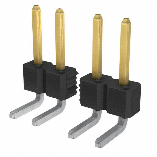
BERGSTIK® UNSHROUDED
RIGHT ANGLE HEADERS STANDARD SIZES
APPLICATION
PRODUCT
0.62 square pin
0.62 square pin
Recommended PCB Layouts
Dimension in mm
14
�BERGSTIK® UNSHROUDED
RIGHT ANGLE HEADERS STANDARD SIZES
TECHNICAL INFORMATION
MATERIALS
SPECIFICATIONS
• Housing: High temperature thermoplastic, Black
•
File no. E66906
• Flammability Rating: UL94V-0
• �
File no. LR46923
• Pin: Phosphor-bronze
• Product Drawing: 77315/ 77317
• Plating: Gold or Tin over 1.27μm (50μin.) Nickel
• Product Specification: BUS-12-114
ELECTRICAL PERFORMANCE
APPROVALS AND CERTIFICATIONS
• Current Rating: 3A per contact
• R
� oHS compatible according to the European Union Directive
2002/95/IEC
• Insulation Resistance: 5000MΩ min
• Dielectric Withstanding Voltage: 1500V
PACKAGING
ENVIRONMENTAL PERFORMANCE
• Bags
• Operating Temperature: -65°C to +125°C
PROCESSING INFORMATION
MECHANICAL PERFORMANCE
• C
� ompatible with wave, vapor-phase, and IR reflow soldering
processes
• Retention Force: 9 N min.
PART NUMBER SELECTOR
XXXXX
BASE PART
NUMBER
-
X
XX
PLATING
CODE
PIN STYLE
LENGTH
-
XX
XX
TOTAL
POSITIONS
LEAD-FREE
THT
Single row
77315
Double row
77317
0.76μm (30μin.) Gold or GXT on
mating area, tin on solder side
1
0.38μm (15μin.) Gold or GXT on
contact area, tin on solder side
Tin
Mating
Solder
8
5.84
4
LF
Single row THT
02 to 36
Double row THT
04 to 72
Pin Style
77315
77317
2.57
01
03
5.84
3.05
18
04
6.75
2.90
24
12
www.fci.com/products/bergstik
15
�BOARD/WIRE-TO-BOARD
CONNECTORS
BERGSTIK® UNSHROUDED
RIGHT ANGLE HEADERS SPECIAL SIZES
APPLICATION
PRODUCT
0.62 square pin
0.62 square pin
Recommended PCB Layouts
Dimension in mm
16
�BERGSTIK® UNSHROUDED
RIGHT ANGLE HEADERS SPECIAL SIZES
TECHNICAL INFORMATION
MATERIALS
SPECIFICATIONS
• Housing: High temperature thermoplastic, Black
•
File no. E66906
• Flammability Rating: UL94V-0
• �
File no. LR46923
• Pin: Phosphor-bronze
• Product Drawing: 55101/ 55102/ 68015/ 68020
• Plating: Gold or Tin over 1.27μm (50μin.) Nickel
• Product Specification: BUS-12-114
ELECTRICAL PERFORMANCE
APPROVALS AND CERTIFICATIONS
• Current Rating: 3A per contact
• R
� oHS compatible according to the European Union Directive
2002/95/IEC
• Insulation Resistance: 5000MΩ min
• Dielectric Withstanding Voltage: 1500V
PACKAGING
ENVIRONMENTAL PERFORMANCE
• Bags
• Operating Temperature: -65°C to +125°C
PROCESSING INFORMATION
MECHANICAL PERFORMANCE
• C
� ompatible with wave, vapor-phase, and IR reflow soldering
processes
• Retention Force: 9N min.
• Retentive Leg Insertion Force: >44.48N max.
• Retentive Leg Board Retention: 2.22N
PART NUMBER SELECTOR
Customize your own part number using custom dimensions (Please allow for initial setup on our system)
XXXXX
BASE PART
NUMBER
-
X
XX
PLATING
CODE
TOTAL
POSITIONS
-
XXX
XXX
XX
MATING
DIMENSION
SOLDER SIDE
DIMENSION
LEAD-FREE
LF
THT
Single row
68015
Single row
01 to 36
Double row
68020
Double row
02 to 72
0.76μm (30μin.) Gold or GXT
1
0.38μm (15μin.) Gold or GXT
2
Tin
4
In 0.1mm increments
min. = 2.0mm
max. = 14.7mm
e.g. 030 = 3.0mm
In 0.1mm increments
min. = 2.3mm
max. = 15.2mm
e.g. 135 = 13.5mm
Note: 1. Bend dimension 1.52mm only
2. The total combined dimension for mating and solder side may not exceed 25.5mm
www.fci.com/products/bergstik
17
�BOARD/WIRE-TO-BOARD
CONNECTORS
BERGSTIK® UNSHROUDED
STACKING HEADERS
APPLICATION
Board spacing = stack height of header+ height of the
receptacle (See application drawings on next page)
PRODUCT
Recommended PCB Layouts
Dimension in mm
18
�BERGSTIK® UNSHROUDED
STACKING HEADERS
TECHNICAL INFORMATION
MATERIALS
SPECIFICATIONS
• Housing: High temperature thermoplastic, Black
•
File no. E66906
• Flammability Rating: UL94V-0
• �
File no. LR46923
• Pin: Phosphor-bronze
• Product Drawing: By 5-digit base part number
• Plating: Gold or Tin over 1.27μm (50μin.) Nickel
• Product Specification: BUS-12-114
ELECTRICAL PERFORMANCE
APPROVALS AND CERTIFICATIONS
• Current Rating: 3A per contact
• R
� oHS compatible according to the European Union Directive
2002/95/IEC
• Insulation Resistance: 5000MΩ min
• Dielectric Withstanding Voltage: 1500V
PACKAGING
ENVIRONMENTAL PERFORMANCE
• Bags
• Operating Temperature: -65°C to +125°C
PROCESSING INFORMATION
MECHANICAL PERFORMANCE
• C
� ompatible with wave, vapor-phase, and IR reflow soldering
processes
• Retention Force: 9N min.
PART NUMBER SELECTOR
Customize your own part number using custom dimensions (Please allow for initial setup on our system)
XX
X
X
X
54
LEAD
SOLDER SIDE
DIMENSION
ROW
OPTION
THT
1
SMT
2
2.41mm
1
3.05mm
2
SMT
(double
row only)
4
Single row
(THT only)
1
Double row
2
-
X
XX
XX
PLATING
CODE
PIN STYLE
LENGTH
TOTAL
POSITIONS
0.76μm (30μin.) Gold
or GXT on contact
area, tin on solder side
0.38μm (15μin.) Gold or
GXT on contact area,
tin on solder side
XXXX
STACK
HEIGHT
XX
LEAD-FREE
LF
1
8
Overall* THT
Overall* SMT
Pin Style
12.20
10.42
01
13.50
11.72
02
15.90
14.12
03
6.76
14.98
04
17.65
15.87
05
18.91
17.13
06
20.96
19.18
23.50
XX.XX = mm
Specify mm
i.e. 08.50 = 8.50mm in
0.50mm increments
08.00 min.
- 25.00 max.
THT
09.50 min.
- 26.00 max.
SMT
Single row (THT)
02 to 36
07
Double row (THT)
04 to 72
21.72
08
Double row (SMT)
04 to 50
26.04
24.26
09
28.58
26.80
10
31.12
29.34
11
33.66
31.88
12
*Other overall lengths available upon request (Up to 65mm)
www.fci.com/products/bergstik
19
�FCIBERG0615EA4
www.fci.com
For more information, please contact: communications@fci.com
�


 工商网监
湘ICP备2023018690号
工商网监
湘ICP备2023018690号
