NTC Type BR Series
Glass Encapsulated
Bead Thermistors
Features
Type BR11/14/16/25
Type B32/42/55
Small glass encapsulated bead thermistors on fine
diameter alloy lead-wires.
Large glass encapsulated bead thermistors on fine
diameter platinum alloy lead-wires.
• Suitable for most low cost temperature measurement, control
or compensation applications
• Suitable for most low cost temperature measurement, control
or compensation applications
• Very fast thermal response times
• Fast thermal response times
• Rugged glass encapsulation provides hermetic seal and better
strain relief than small glass coated bead thermistors
• Rugged glass encapsulation provides hermetic seal and better
strain relief than large glass coated bead thermistors
• Long term stability is better than small glass coated bead
thermistors
• Long term stability is better than large glass coated bead
thermistors
• Suitable for self-heated applications such as liquid level
sensing or gas flow measurement
• Suitable for self-heated applications such as liquid level
sensing or gas flow measurement
• Recommended for all applications where the customer will
perform further assembly operations
• Recommended for all applications where the customer will
perform further assembly operations
• Normal operating/storage temperatures range from
• Normal operating/storage temperatures range from
• -112°F (-80°C) to: 221°F (105°C) for Material system E0, 392°F
(200°C) for Material systems A1 through A4, 572°F (300°C) for
Material systems A5 through D17
• -112°F (-80°C) to: 221°F (105°C) for Material system E0, 392°F
(200°C) for Material systems A1 through A4, 572°F (300°C) for
Material systems A5 through D17
• Unaffected by severe environmental exposures, including
nuclear radiation
• Unaffected by severe environmental exposures, including
nuclear radiation
• Intermittent operation to 1112°F (600°C) is permissible,
however, stability will be degraded
• Intermittent operation to 1112°F (600°C) is permissible,
however, stability will be degraded
Amphenol
Advanced Sensors
�Type BR Series Specifications
Type BR11/14/16/23
Thermal and Electrical Properties
The following lists the thermal and electrical
properties for all small ruggedized thermistors.
All definitions and test methods per
MIL-PRF-23648.
Body Dimensions
BR11
• Nominal diameter: 0.011 in (0.28 mm)
• Maximum diameter: 0.012 in (0.30 mm)
• Maximum length: 0.0242 in (0.610 mm)
BR14
• Nominal diameter: 0.014 in (0.36 mm)
• Maximum diameter: 0.016 in (0.41 mm)
• Maximum length: 0.032 in (0.81 mm)
BR16
• Nominal diameter: 0.016 in (0.41 mm)
• Maximum diameter: 0.017 in (0.43 mm)
• Maximum length: 0.034 in (0.86 mm)
BR23
• Nominal diameter: 0.023 in (0.58 mm)
• Maximum diameter: 0.025 in (0.63 mm)
• Maximum length: 0.056 in (1.46 mm)
Lead-Wires
BR11
• Nominal diameter: 0.0007 in (0.02 mm)
• Maximum lead length: 0.312 in (7.9 mm)
• Lead material: platinum alloy
• Available cuts: “K” adjacent or “P” opposite
BR14
• Nominal diameter: 0.0011 in (0.03 mm)
• Maximum lead length: 0.312 in (7.9 mm)
• Lead material: platinum alloy
• Available cuts: “K” adjacent or “P” opposite
BR16
• Nominal diameter: 0.0011 in (0.03 mm)
• Maximum lead length: 0.312 in (7.9 mm)
• Lead material: platinum alloy
• Available cuts: “K” adjacent or “P” opposite
BR23
• Nominal diameter: 0.002 in (0.05 mm)
• Maximum lead length: 0.312 in (8 mm)
• Lead material: platinum alloy
• Available cuts: “K” adjacent or “P” opposite
2
Type BR Series dimensions
Material System
25/125
Ratio
(Table A)
Nominal Resistance Range at 77°F (25°C)
Code
Letter
R vs T
Curve
E
0
5.0
A
1
11.8
1 to 1.5 kΩ
300 to 680 Ω
300 to 680 Ω
300 to 680 Ω
A
2
12.5
1.5 to 3.6 kΩ
680 to 1.6 kΩ
680 to 1.6 kΩ
680 to 1.6 kΩ
A
3
14
3.6 to 7.5 kΩ
1.6 to 3.6 kΩ
1.6 to 3.6 kΩ
1.6 to 3.6 kΩ
A
4
16.9
7.5 to 15 kΩ
3.6 to 6.8 kΩ
3.6 to 6.8 kΩ
3.6 to 6.8 kΩ
A
5
19.8
15 to 51 kΩ
6.8 to 27 kΩ
6.8 to 27 kΩ
6.8 to 27 kΩ
A
6
22.1
A
7
22.7
51 to 150 kΩ
B
8
29.4
150 to 270 kΩ 75 to 130 kΩ
75 to 130 kΩ
75 to 130 kΩ
B
9
30.8
270 to 470 kΩ 130 to 240 kΩ
130 to 240 kΩ
130 to 240 kΩ
BR11
BR14
BR16
_
_
_
_
_
27 to 75 kΩ
_
27 to 75 kΩ
BR23
_
_
27 to 75 kΩ
B
10
32.3
470 to 750 kΩ 240 to 360 kΩ
240 to 360 kΩ
240 to 360 kΩ
B
11
35.7
750 to 1.6 MΩ 360 to 820 kΩ
360 to 820 kΩ
360 to 820 kΩ
B
12
38.1
1.6 to 2.7 MΩ
820 to 1.3 MΩ 820 to 1.3 MΩ
820 to 1.3 MΩ
B
13
45
2.7 to 6.8 MΩ
1.3 to 3.36 MΩ 1.3 to 3.36 MΩ
1.3 to 3.36 MΩ
6.8 to 10 MΩ
3.3 to 6.86 MΩ 3.3 to 6.86 MΩ
3.3 to 6.86 MΩ
6.8 to 10 MΩ
6.8 to 10 MΩ
B
14
48.1
B
15
56.5
_
D
16
75.6
_
_
_
_
D
17
81
_
_
_
_
Thermal Time Constant
BR11
• Still air at 77°F (25°C): 0.8 second
• Plunge into water: 12 msec
BR14
• Still air at 77°F (25°C): 1 second
• Plunge into water: 14 msec
BR16
• Still air at 77°F (25°C): 1.2 second
• Plunge into water: 16 msec
BR23
• Still air at 77°F (25°C): 1.7 second
• Plunge into water: 40 msec
6.8 to 10 MΩ
�Type BR Series Specifications
Dissipation Constant
Type BR32/42/55
BR11
• Still air at 77°F (25°C): 0.065 mW/°C
• Still water at 77°F (25°C): 0.33 mW/°C
Thermal and Electrical Properties
BR14
• Still air at 77°F (25°C): 0.10 mW/°C
• Still water at 77°F (25°C): 0.50 mW/°C
BR16
• Still air at 77°F (25°C): 0.12 mW/°C
• Plunge into water: 0.60 mW/°C
BR23
• Still air at 77°F (25°C): 0.18 mW/°C
• Plunge into water: 0.9 mW/°
Power Rating (In Air)
BR11
• Maximum Power Rating: 0.007 W
• 100% Maximum Power To: 257°F (125°C)
• Derated to 0% at: 572°F (300°C)
BR14
• Maximum Power Rating: 0.015 W
• 100% Maximum Power To: 257°F (125°C)
• Derated to 0% at: 572°F (300°C)
BR16
• Maximum Power Rating: 0.015 W
• 100% Maximum Power To: 257°F (125°C)
• Derated to 0% at: 572°F (300°C)
BR23
• Maximum Power Rating: 0.020 W
• 100% Maximum Power To: 257°F (125°C)
• Derated to 0% at: 572°F (300°C)
Options
•
•
•
•
•
•
•
•
•
•
•
Non-standard resistance tolerances
Non-standard resistance values
Specify reference temperature(s) if it is not 77°F (25°C)
Mounting in special housings or enclosures
Longer continuous leads
Welded or soldered extension leads_specify lead
material, diameter, length, and insulation, if any.
Solderable or weldable/solderable leads
Leads can be pre-tinned or treated for improved
soldering
Calibration_specify temperature(s)
Interchangeable pairs or sets, R-vs-T curve matching;
specify temperature range(s) and tolerance(s)
Special aging and conditioning for high reliability
applications
The following lists the thermal and electrical properties for
all large ruggedized thermistors. All definitions and test
methods per MIL-PRF-23648.
Body Dimensions
BR32
• Nominal diameter: 0.032 in (0.81 mm)
• Maximum diameter: 0.033 in (0.84 mm)
• Maximum length: 0.084 in (2.1 mm)
BR42
• Nominal diameter: 0.042 in (1.16 mm)
• Maximum diameter: 0.046 in (1.2 mm)
• Maximum length: 0.095 in (2.4 mm)
BR55
• Nominal diameter: 0.055 in (1.41 mm)
• Maximum diameter: 0.060 in (1.5 mm)
• Maximum length: 0.120 in (3 mm)
Lead-Wires
BR32
• Nominal diameter: 0.003 in (0.08 mm)
• Maximum lead length: 0.312 in (7.9 mm)
• Lead material: platinum alloy
• Available cuts: “K” adjacent or “P” opposite
BR42
• Nominal diameter: 0.004 in (0.10 mm)
• Maximum lead length: 0.312 in (7.9 mm)
• Lead material: platinum alloy
• Available cuts: “K” adjacent or “P” opposite
BR55
• Nominal diameter: 0.004 in (0.10 mm)
• Maximum lead length: 0.312 in (7.9 mm)
• Lead material: platinum alloy
• Available cuts: “K” adjacent or “P” opposite
Thermal Time Constant
BR32
• Still air at 77°F (25°C): 4.5 second
• Plunge into water: 90 msec
BR42
• Still air at 77°F (25°C): 5 second
• Plunge into water: 140 msec
BR55
• Still air at 77°F (25°C): 7 second
• Plunge into water: 200 msec
3
�Material System
Code
Letter
R vs T
Curve
Options
(Table B)
Nominal Resistance Range
at 77°F (25°C)
25/125
Ratio
BR32
BR42
BR55
E
0
5.0
-
30 to 51 Ω
30 to 51 Ω
A
1
11.8
100 to 300 Ω
51 to 150 Ω
51 to 150 Ω
A
2
12.5
300 to 750 Ω
150 to 360 Ω
150 to 360 Ω
A
3
14
750 to 1.5 kΩ
360 to 750 Ω
360 to 750 Ω
A
4
16.9
1.5 to 3.0 kΩ
750 to 1.5 kΩ
750 to 1.5 kΩ
A
5
19.8
3.0 to 6.8 kΩ
1.5 to 3.6 kΩ
1.5 to 3.6 kΩ
A
6
22.1
6.8 to 13 kΩ
3.6 to 6.2 kΩ
3.6 to 6.2 kΩ
A
7
22.7
13 to 18 kΩ
6.2 to 9.1 kΩ
6.2 to 9.1 kΩ
B
8
29.4
18 to 51 kΩ
9.1 to 27 kΩ
9.1 to 27 kΩ
B
9
30.8
51 to 82 kΩ
27 to 43 kΩ
27 to 43 kΩ
B
10
32.3
82 to 150 kΩ
43 to 75 kΩ
43 to 75 kΩ
B
11
35.7
150 to 330 kΩ
75 to 160 kΩ
75 to 160 kΩ
B
12
38.1
330 to 680 kΩ
160 to 360 kΩ
160 to 360 kΩ
B
13
45
680 to 1.5 MΩ
360 to 750 kΩ
360 to 750 kΩ
•
•
•
•
•
•
•
•
•
•
•
Non-standard resistance tolerances
Non-standard resistance values
Specify reference temperature(s) if it is not 77°F (25°C)
Mounting in special housings or enclosures
Longer continuous leads
Welded or soldered extension leads; specify lead material,
diameter, length, and insulation, if any.
Solderable or weldable/solderable leads
Leads can be pre-tinned or treated for improved soldering
Calibration_specify temperature(s)
Interchangeable pairs or sets, R-vs-T curve matching; specify
temperature range(s) and tolerance(s)
Special aging and conditioning for high reliability applications
Ordering Information
B
14
48.1
1.5 to 3.0 MΩ
750 to 1.5 MΩ
750 to 1.5 MΩ
The code number to be ordered may be specified as follows:
B
15
56.5
3.0 to 6.2 MΩ
1.5 to 3.0 MΩ
1.5 to 3.0 MΩ
Code
Type
D
16
75.6
6.2 to 10 MΩ
3.0 to 8.2 MΩ
3.0 to 8.2 MΩ
BR
Ruggedized bead structure
D
17
81
8.2 to 20 MΩ
8.2 to 20 MΩ
Code
11
14
16
23
32
42
55
-
Dissipation Constant
BR32
• Still air at 77°F (25°C): 0.285 mW/°C
• Still water at 77°F (25°C): 1.4 mW/°C
BR42
• Still air at 77°F (25°C): 0.33 mW/°C
• Still water at 77°F (25°C): 1.65 mW/°C
BR55
• Still air at 77°F (25°C): 0.5 mW/°C
• Still water at 77°F (25°C): 2.50 mW/°C
Power Rating (In Air)
BR32
• Maximum Power Rating: 0.035 W
• 100% Maximum Power To: 302°F (150°C)
• Derated to 0% at: 572°F (300°C)
BR42
• Maximum Power Rating: 0.042 W
• 100% Maximum Power To: 302°F (150°C)
• Derated to 0% at: 572°F (300°C)
BR55
• Maximum Power Rating: 0.050 W
• 100% Maximum Power To: 302°F (150°C)
• Derated to 0% at: 572°F (300°C)
Amphenol
Advanced Sensors
Diameter
11 mils
14 mils
16 mils
23 mils
32 mils
42 mils
55 mils
Code
K
P
Lead Configuration
Adjacent leads with stub ends glass coated
Opposite leads
Code
X
Material System Code
See table A or table B for code number
Code Power
X
Zero-power resistance as 77°F (25°C)
(see note 2 for code number)
BR -
____ - ____
-
____
-
____
-
Code Tolerance*
F 1
G
2
J 5
K
10
L 15
M
20
N
25
P
30
Q
40
R
50
S
Non-standard (consult factory)
____
Typical model number
Special tolerances are available upon request. Consult factory for special resistance tolerances, nonstandard resistances and/or non-standard temperatures.
*The zero-power resistance at 77°F (25°C), expressed inΩ, is identified by a
three digit code number. The first two digits represent significant figures, and
the last digit specifies the number of zeros to follow. Example: 10k Ω= “103”.
The standard resistance values are from the 24-Value series decade as specified
in Military Standard MS90178.
1.0 / 1.1 / 1.2 / 1.3 / 1.5 / 1.6 / 1.8 / 2.0 / 2.2 / 2.4 / 2.7 / 3.0
3.3 / 3.6 / 3.9 / 4.3 / 4.7 / 5.1 / 5.6 / 6.2 / 6.8 / 7.5 / 8.2 / 9.1
www.amphenol-sensors.com
© 2014 Amphenol Corporation. All Rights Reserved. Specifications are subject to change without notice.
Other company names and product names used in this document are the registered trademarks or
trademarks of their respective owners.
AAS-920-308B - 09/2014
�
很抱歉,暂时无法提供与“BR42KA502M”相匹配的价格&库存,您可以联系我们找货
免费人工找货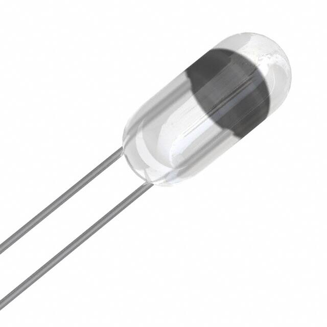


 工商网监
湘ICP备2023018690号
工商网监
湘ICP备2023018690号
