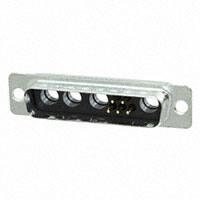
TW
Steel-Tin plating
High temperature black thermoplastic
Female: machined bronze
Male: machined brass
Flash,15µ" Au over 79µ" Ni min.
or 30µ" Au over 79µ" Ni min.
Shielded contacts
Female: machined bronze
Material
Male: machined brass
Plating
Inner conductor 15µ" Au or 30µ" Au over 79µ" Ni
Outer ring
Flash Au over 79µ" Ni
Terminations
Tinned
Except solder cup and crimp terminations 30µ” Au
Power contacts
Female: machined bronze
Material
Male: machined brass
Plating
Contacts
Flash, 15µ" Au or 30µ" Au over 79µ" Ni
Terminations
Tinned
Except solder cup and crimp terminations 15µ” Au
Brackets
Steel-Tin plating
Front jackscrews
Brass-Tin plating
Rear clinch nuts
Brass-Tin plating
Boardlocks
Bronze-Tin plating
Stand-off
Brass-Tin plating
Mechanical data
With or without dimples
-55°C +155°C Shells
(with peak of 180°C) Contact retention force in dielectric material > 40N
56 days (40°C -95% RH) Maximum mating and unmating force
48 hours With dimples
E size = 70 N
A size = 80 N
B size = 100 N
C size = 150 N
D size = 180 N
Without dimples
E size = 30 N
A size = 50 N
B size = 80 N
C size = 120 N
D size = 160 N
Compatible with process
IR - Air convection
260°C for 20s.
Resistance to solder iron heat
260°C for 30s.
Mating cycles 100 (class III) 200 (class ll) 500 (class l)
Climatic Data
Operating temperature
Damp heat
Salt spray
Electrical Data
Current rating
Signal contacts
7.5 A. with 10 A. peak
Power contacts
PCB terminations
10 to 40 A.
Solder cup terminations
10 to 40 A.
Crimp terminations
10 to 40 A.
Shielded contacts
0.5 A.
Voltage rating
Signal and power contacts 300 V.R.M.S. at 50 Hz
Shielded contacts
150 V.R.M.S. at 50 Hz
Shielded contacts
Frequency range
0-1 GHz
Attenuation
0.2dB
V. S. W. R.
1.4(+0.04/GHz)
Characteristic impedance
50 Ohms
Dielectric withstanding
voltage
≥ 1000 V.R.M.S. at 50Hz
Insulation resistance ≥ 5000 M Ohms at 500 VDC
Contact resistance
≤ 5m Ohms
Shell resistance
≤ 1m Ohm
(electrical grounding)
Amphenol D’Sub TW Hybrid Series permits
a mix of contacts including signal, power,
shielded, high voltage and fiber optics in the
same housing with different contacts
arrangements.
This economic series was first developed from
our military series, and has improved features:
- new contacts
- new high temperature black thermoplastic insert
- PCB configurations come preloaded with
fixed contacts and brackets.
These connectors are supplied with screw
machined contacts fixed in the insulator.
A complete range of housings are also
available for cable application.
A full series of
arrangements
compatible with
reflow process
• Commercial
• Medical
• Industrial
• Telecom
• Any application requiring
optimization of space
TW / E1
Materials and plating
Shells
Insulators
Signal contacts
Material
Plating finish
DESCRIPTION
• Connectors according to: MIL C24308 - NFC93425 - HE507
APPLICATIONS
CONTENT
Hybrid D’Sub series
�OVERALL DIMENSIONS
Shell and contact plating
CLASS 3
CLASS 2
Flash Gold Signal & Power
CLASS 1
.4um(15u”) Signal, Power, Coax .76um(30u”) Signal, Power Coax
Type
Shell + Plating
Type
Shell + Plating
Type
Shell + Plating
76
Tin plated shell
Plug or Socket
77
Tin plated shell
Plug or Socket
177
Tin plated shell
Plug or Socket
716
Tin plated shell
with grounding
dimples-plug
only
717
Tin plated shell
with grounding
dimples-plug
only
777
Tin plated shell
with grounding
dimples-plug
only
Housing arrangement
Male front view
Arrangement..
Shell size........
2W2
E
P2W2
E
P3W3
E
Arrangement...
Shell size........
5W1
A
7W2
A
11W1
A
Arrangement...
Shell size........
3W3
A
5W5
B
9W4
B
Arrangement...
Shell size........
13W3
B
17w2
B
21W1
B
Arrangement...
Shell size........
27W2
C
13W6
C
17W5
C
Arrangement...
Shell size........
21WA4
C
8W8
C
25W3
C
Arrangement...
Shell size........
24W7
D
36W4
D
43W2
D
2
�Rear view
Front view
1.5
10˚
H
F /F’
A
B
B’
0.9
J
D’ D E
ø 3.1
Shell
size
Contact
P: Pin
S: Socket
P
E
S
P
A
S
P
B
S
P
C
S
P
D
S
A
±0.25
(±.010)
B
0/-0.20
(0/-.008)
B’
+0.20/0
(+.008/0)
C
D
±0.10
(±.004)
0/-0.25
(0/-.010)
16.8
(.661”) 25.0
30.7
(.984”) 8.0
(1.209”) 16.4
(.315”)
(.646”)
25.1
(.988”) 33.3
39.0
(1.311”) 8.0
(1.535”) 24.8
(.315”)
(.976”)
38.8
(1.528”) 47.0
52.9
(1.850”) 8.0
(2.083”) 38.5
(.315”)
(1.513”)
55.3
(2.177”) 63.5
69.2
(2.500”) 8.0
(2.724”) 54.9
(.315”)
(2.161”)
52.7
(2.075”) 61.1
66.8
(2.406”) 10.9
(2.630”) 52.5
(.429”)
(2.067”)
TECHNICAL DATA
Shell size dimensions
C
G /G’
D’
+0.25/0
(+.010/0)
8.2
(.323”)
8.2
(.323”)
8.2
(.323”)
8.2
(.323”)
11.0
(.433”)
E
±0.20
(±.008)
F
F‘
G
+0.05/-0.20 +0.10/-0.20 +0.10/-0.20
(+.002/-.008) (+.004/-.008) (+.004/-.008)
12.4
(.488”)
12.4
(.488”)
12.4
(.488”)
12.4
(.488”)
15.2
(.598”)
11.1
(.437)
11.1
(.437)
11.1
(.437)
11.1
(.437)
11.1
(.437)
10.9
(.429”)
10.9
(.429”)
11.0
(.433”)
11.0
(.433”)
11.0
(.433”)
6.2
(.244”)
6.2
(.244”)
6.2
(.244”)
6.2
(.244”)
6.2
(.244”)
G’
J
H
±0.10
(±.004)
5.9
(.232”)
5.9
(.232”)
5.8
(.228”)
5.8
(.228”)
5.8
(.228”)
0/-0.50
(0/-.020)
+0.10/-0.40
(+.004/-.016)
19.4 11.0
(.764”) (.433”)
27.7 11.0
(1.091”) (.433”)
41.4 11.0
(1.630”) (.433”)
57.9 11.0
(2.280”) (.433”)
55.5 13.8
(2.185”) (.543”)
Panel cutouts
D
Shell
size
E
A
B
3
C
D
Mounting
method
Front
Rear
Front
Rear
Front
Rear
Front
Rear
Front
Rear
Standard cutout
A
B
10˚
A
±0.20
(±.008)
22.2
(.874”)
20.5
(.807”)
30.5
(1.201”)
28.8
(1.134”)
44.3
(1.744”)
42.5
(1.673”)
60.7
(2.390”)
59.1
(2.327”)
58.3
(2.295”)
56.3
(2.217”)
B
±0.20
(±.008)
11.1
(.437”)
10.2
(.402”)
15.3
(.602”)
14.4
(.567”)
22.1
(.870”)
21.3
(.839”)
30.4
(1.197”)
29.5
(1.161”)
29.2
(1.150”)
28.2
(1.110”)
C
F
D
R
Rd Rading J
C
10˚
G H
D
±0.20
(±.008)
±0.20
(±.008)
25.0
(.984”)
12.5
(.492”)
33.3
(1.311”)
16.7
(.657”)
47.0
(1.850”)
23.5
(.925”)
63.5
(2.500”)
31.7
(1.248”)
61.1
(2.406”)
30.6
(1.205”)
E
±0.20
(±.008)
13.0
(.512”)
11.4
(.449”)
13.0
(.512”)
11.4
(.449”)
13.0
(.512”)
11.4
(.449”)
13.0
(.512”)
11.4
(.449”)
15.8
(.622”)
14.1
(.555”)
F
±0.20
(±.008)
6.5
(.256”)
5.7
(.224”)
6.5
(.256”)
5.7
(.224”)
6.5
(.256”)
5.7
(.224”)
6.5
(.256”)
5.7
(.224”)
7.9
(.311”)
7.1
(.280”)
E
Rd Rading J
C
G
H
±0.20
(±.008)
±0.20
(±.008)
3.0
(.118”)
1.5
(.059”)
3.0
(.118”)
1.5
(.059”)
3.0
(.118”)
1.5
(.059”)
3.0
(.118”)
1.5
(.059”)
3.0
(.118”)
1.5
(.059”)
J
±0.20
(±.008)
2.1
(.083”)
3.4
(.0134”)
2.1
(.083”)
3.4
(.0134”)
2.1
(.083”)
3.4
(.0134”)
2.1
(.083”)
3.4
(.0134”)
2.1
(.083”)
3.4
(.0134”)
TW / E1
Optimal cutout for rear mounting
A
B
øG
�TECHNICAL DATA
Straight connector footprint
1
2
A
3
A
B
A
B
B
Signal tail 0.6 mm Dia. (.024”)
1.6 mm (.063”)PCB
For other PCB thickness: consult factory.
Dimensions
Description
a
4.80 mm
(.189”)
4.80 mm
(.189”)
4.00 mm
(.157”)
5.30 mm
(.209”)
Power 3.2mm(.126”) tail dia 1
Power 2.0mm(.078”) tail dia 1
Shielded
3
Signal
2
b
7.2 mm
(.283”)
7.2 mm
(.283”)
7.2 mm
(.283”)
11.50 mm
(.453”)
Straight contact combinations
Arrangement with signal contacts
Arrangement without signal contacts
2W2 - 3W3 - 5W5 - 8W8
See above dimensions
Size 8 and 20 Contacts
See above dimensions
Size 8 Contacts
P 3SY
Power 3.2 mm DIA. (.126”)
(20 to 40 A) and signal
P 3Y
Power only
3.2 mm DIA. (.126”)
(20 to 40 A)
P 2SY
Power 2 mm DIA. (.078”)
(10 to 20 A) and signal
P 2Y
Power only
2 mm DIA. (.078”)
(10 to 20 A)
CY
Shielded only
CSY
Shielded and signal
SY
Signal only
No reference
Signal (Size 20)
with solder cup terminations
Housing preloaded with contacts
4
�1
2
B
C
3
B
C
B
C
A
A
Signal tail 0.6 mm Dia. (.0236”)
1.6 mm (.063”) PCB
For other PCB thickness: consult factory.
Description
TECHNICAL DATA
Right angle connector footprint
A
Europe
HE 5 pattern =
- Euro height
- Euro footprint
pitch between
2 rows: .100”
Mix
Mixed pattern =
- MIL height
- Euro footprint
pitch between
2 rows: .100”
a
b
c
a
-
-
-
b
MIL
MIL pattern =
- MIL height
- MIL footprint
pitch between
2 rows: .112”
c
a
b
c
10.30mm 6.30mm 10.00mm 10.30mm 6.30mm 10.00mm
(.406”) (.248”) (.394”) (.406”) (.248”) (.394”)
Shielded
1
Signal
2
10.30mm 7.20mm 11.20mm 10.30mm 6.30mm 9.50mm 8.10mm 6.30mm 9.50mm
(.406”) (.283”) (.441”) (.406”) (.248”) (.374”) (.319”) (.248”) (.374”)
Power 2.0mm(.078”) tail dia 3
11.57mm 7.20mm 10.50mm 11.57mm 6.30mm 9.50mm 9.52mm 6.30mm 9.50mm
(.456”) (.283”) (.413”) (.456”) (.248”) (.374”) (.375”) (.248”) (.374”)
Power 3.2mm(.126”) tail dia 3
21.46mm 7.20mm 10.50mm 21.46mm 6.30mm 9.50mm 21.46mm 6.30mm 9.50mm
(.845”) (.283”) (.413”) (.845”) (.248”) (.374”) (.845”) (.248”) (.374”)
Note: above dimensions correspond to sizes E to C. Consult factory for D sizes.
Connector comes equipped with contacts and brackets.
Right angle contacts combinations
5
Arrangement without signal contacts
2W2 - 3W3 - 5W5 - 8W8
European
footprint
Mixed
footprint
MIL (U.S.)
footprint
Size 8 and
20 Contacts
European
footprint
Mixed
footprint
MIL (U.S.)
footprint
Size 8 contacts
only
EP3SV
HP3SV
MP3SV
Power 3.2 mm
DIA. (.126”) (20 to
40 A) and signal
EP3V
HP3V
MP3V
Power only
3.2 mm DIA. (.126”)
(20 to 40 A)
EP2SV
HP2SV
MP2SV
Power 2 mm
DIA. (.078”) (10 to
20 A) and signal
EP2V
HP2V
MP2V
-
HCSV
MCSV
Shielded and signal
-
HCV
MCV
ESV
HSV
MSV
Signal only
Power only
2.0 mm DIA. (.078”)
(10 to 20 A)
Shielded only
TW / E1
Arrangement with signal contacts
�Right angle version
Connectors come equipped with metal brackets
BLANK: 3.10mm (.122”) dia mounting hole
RM6: metal brackets + boardlock
Metal bracket
RM6
Straight version
BLANK: 3.10mm (.122”) dia mounting hole
RM54: 4-40 threaded
RM53: M3 threaded
1.5 max.
(.059 max.)
7.2 (.283)
RM5x
RM8x
RM84: 4-40 threaded
RM83: M3 threaded
A514: blind mating system
FM: float mounting system
3.6 max.
(.141 max.)
ø2.2 (.086)
+ 0.25
3.5
(.137)
19.9
(.783)
ø2.25
(.088)
ø3 0
(.118)
Straight and right angle version
4R: 4-40 rear nut
3R: M3 rear nut
4F: 4-40 front female screwlock
3F: M3 front female screwlock
(.1 3.4
34
)
TECHNICAL DATA
Mounting options
7.1 9)
7
(.2
6
�4.80
(.189”)
5.20
(.205”)
5.20
(.205”)
4.80
(.189”)
High temperature
plastic locking
ring
TECHNICAL DATA
High power contacts
22
(.866”)
øA
22
(.866”)
øB
P/N
Plug
øA
øB
16
(.622”)
Solder cup version
Current
Socket
Dimensions
A mm (inch)
B mm (inch)
L 17DM 53745-8
L 17DM 53744-7
10 to 20 Amp.
1.80 (.071”)
2.55 (.100”)
L 17DM 53745-7
L 17DM 53744-6
20 to 30 Amp.
2.80 (.110”)
3.70 (.145”)
L 17DM 53745-1
L 17DM 53744-1
30 to 40 Amp.
4.80 (.189”)
5.60 (.220”)
Trim dimensions: 7.5 mm (.295”)
Crimp version
øB
22
(.866”)
P/N
Plug
øA
øB
Socket
Current
Dimensions
A mm (inch)
B mm (inch)
L 17DM 53745-208
L 17DM 53744-207
10 to 20 Amp.
1.80 (.071”)
2.55 (.100”)
L 17DM 53745-207
L 17DM 53744-206
20 to 30 Amp.
2.80 (.110”)
3.70 (.145”)
L 17DM 53745-201
L 17DM 53744-201
30 to 40 Amp.
4.80 (.189”)
5.60 (.220”)
Trim dimensions: 7.5 mm (.295”)
Contact plating
Part number option
Flash Gold
17DMxxxxx-x G
0.4µm(15µ”) Au
Standard part number as above
0.76µ(30µ”) Au
17DMxxxxx-x C309
7
TW / E1
øA
16
(.622”)
22
(.866”)
�TECHNICAL DATA
Straight shielded contacts
Crimp ferrule and inner solder
A
B
B
øD
øD
F
Type
P/N
plug
plug
plug
plug
socket
socket
socket
socket
L17DM 53740
L17DM 53740-1
L17DM 53740-3
L17DM 53740-5
L17DM 53742
L17DM 53742-1
L17DM 53742-3
L17DM 53742-5
E
G
Cable - RG
Dimensions (inch)
Trim dimensions (inch)
B
D
F
G
A Max
E
178 B/U
18.8 (740”) 23.6 (.929”) 1.0 (.039”)
7.9 (.311”) 6.3 (.248”) 2 (.078”)
18.8 (740”) 23.6 (.929”) 1.7 (.066”) 179 B/U 316 B/U 7.9 (.311”) 6.3 (.248”) 2 (.078”)
180 B/U
21.5 (846”) 23.6 (.929”) 2.8 (.110”)
9.5 (.374”) 7.9 (.311”) 2 (.078”)
58 C/U
21.5 (846”) 23.6 (.929”) 3.2 (.126”)
9.5 (.374”) 7.9 (.311”) 2 (.078”)
178 B/U
18.8 (740”) 23.6 (.929”) 1.0 (.039”)
7.9 (.311”) 6.3 (.248”) 2 (.078”)
18.8 (740”) 23.6 (.929”) 1.7 (.066”) 179 B/U 316 B/U 7.9 (.311”) 6.3 (.248”) 2 (.078”)
180 B/U
21.5 (846”) 23.6 (.929”) 2.8 (.110”)
9.5 (.374”) 7.9 (.311”) 2 (.078”)
58 C/U
21.5 (846”) 23.6 (.929”) 3.2 (.126”)
9.5 (.374”) 7.9 (.311”) 2 (.078”)
Ferrule and inner solder
A
B
B
øD
øD
F
Type
P/N
short plug
plug
plug
plug
plug
short socket
socket
socket
socket
socket
L17DM 53740-5000
L17DM 53740-5001
L17DM 53740-5002
L17DM 53740-5005
L17DM 53740-5008
L17DM 53742-5000
L17DM 53742-5001
L17DM 53742-5002
L17DM 53742-5004
Dimensions (inch)
A Max
17.0 (669”)
18.8 (740”)
21.5 (846”)
21.5 (846”)
18.8 (740”)
17.0 (669”)
18.8 (740”)
21.5 (846”)
21.5 (846”)
L17DM 53742-5006 18.8 (740”)
B
21.8 (.858”)
23.6 (.929”)
26.3 (1.035”)
26.3 (1.035”)
23.6 (.929”)
21.8 (.858”)
23.6 (.929”)
26.3 (1.035”)
26.3 (1.035”)
23.6 (.929”)
Cable - RG
D
1.0 (.039”)
178 B/U
1.7 (.066”) 179 B/U 316 B/U
2.8 (.110”)
180 B/U
3.2 (.126”)
58 C/U
1.0 (.039”)
178 B/U
1.0 (.039”)
178 B/U
1.7 (.066”) 179 B/U 316 B/U
2.8 (.110”)
180 B/U
3.2 (.126”)
58 C/U
1.0 (.039”)
178 B/U
E
G
Trim dimensions (inch)
E
7.9 (.311”)
7.9 (.311”)
9.5 (.374”)
9.5 (.374”)
7.9 (.311”)
7.9 (.311”)
7.9 (.311”)
9.5 (.374”)
9.5 (.374”)
7.9 (.311”)
F
6.3 (.248”)
6.3 (.248”)
7.9 (.311”)
7.9 (.311”)
6.3 (.248”)
6.3 (.248”)
6.3 (.248”)
7.9 (.311”)
7.9 (.311”)
6.3 (.248”)
G
2 (.078”)
2 (.078”)
2 (.078”)
2 (.078”)
2 (.078”)
2 (.078”)
2 (.078”)
2 (.078”)
2 (.078”)
2 (.078”)
8
�TECHNICAL DATA
Right angled shielded contact
Crimp ferrule and inner solder
F
A
Type
P/N
plug
plug
plug
plug
socket
socket
socket
socket
L17DM 53741
L17DM 53741-1
L17DM 53741-3
L17DM 53741-4
L17DM 53743-2
L17DM 53743-3
L17DM 53743-5
L17DM 53743-6
E
A
G
Cable - RG
Dimensions (inch)
Trim dimensions (inch)
G
A Max
B
D
E
F
13.5 (.531”) 18.6 (.732”) 1.0 (.039”)
178 B/U
9.5 (.374”) 5.9 (.232”) 1.6 (.062”)
13.5 (.531”) 18.6 (.732”) 1.7 (.066”) 179 B/U 316 B/U 9.5 (.374”) 5.9 (.232”) 1.6 (.062”)
13.5 (.531”) 18.6 (.732”) 2.8 (.110”)
180 B/U
10.7 (.421”) 7.9 (.311”) 2.4 (.094”)
13.5 (.531”) 18.6 (.732”) 3.2 (.126”)
58 C/U
10.7 (.421”) 7.9 (.311”) 2.4 (.094”)
13.5 (.531”) 18.6 (.732”) 1.0 (.039”)
178 B/U
9.5 (.374”) 5.9 (.232”) 1.6 (.062”)
13.5 (.531”) 18.6 (.732”) 1.7 (.066”) 179 B/U 316 B/U 9.5 (.374”) 5.9 (.232”) 1.6 (.062”)
10.7 (.421”) 7.9 (.311”) 2.4 (.094”)
13.5 (.531”) 18.6 (.732”) 2.8 (.110”)
180 B/U
10.7 (.421”) 7.9 (.311”) 2.4 (.094”)
13.5 (.531”) 18.6 (.732”) 3.2 (.126”)
58 C/U
Ferrule and inner solder
B
B
C
F
E
G
C
øD
Type
P/N
plug
plug
plug
plug
socket
socket
socket
socket
L17DM 53741-5000
L17DM 53741-5001
L17DM 53741-5003
L17DM 53741-5004
L17DM 53743-5000
L17DM 53743-5001
L17DM 53743-5003
L17DM 53743-5004
øD
Dimensions (inch)
Trim dimensions (inch)
D
Cable - RG
F
A Max
B
E
G
178 B/U
13.5 (.531”) 18.6 (.732”) 1.0 (.039”)
9.5 (.374”) 5.9 (.232”) 1.6 (.062”)
13.5 (.531”) 18.6 (.732”) 1.7 (.066”) 179 B/U 316 B/U 9.5 (.374”) 5.9 (.232”) 1.6 (.062”)
180 B/U
13.5 (.531”) 18.6 (.732”) 2.8 (.110”)
10.7 (.421”) 7.9 (.311”) 2.4 (.094”)
58 C/U
13.5 (.531”) 18.6 (.732”) 3.2 (.126”)
10.7 (.421”) 7.9 (.311”) 2.4 (.094”)
178 B/U
13.5 (.531”) 18.6 (.732”) 1.0 (.039”)
9.5 (.374”) 5.9 (.232”) 1.6 (.062”)
13.5 (.531”) 18.6 (.732”) 1.7 (.066”) 179 B/U 316 B/U 9.5 (.374”) 5.9 (.232”) 1.6 (.062”)
180 B/U
13.5 (.531”) 18.6 (.732”) 2.8 (.110”)
10.7 (.421”) 7.9 (.311”) 2.4 (.094”)
58 C/U
10.7 (.421”) 7.9 (.311”) 2.4 (.094”)
13.5 (.531”) 18.6 (.732”) 3.2 (.126”)
Crimping tool
9
RG cables
MIL reference
RG 58 C/U
RG 178 B/U
RG 179 B/U
RG 180 B/U
M 22 520/5-05
M 22 520/5-03
M 22 520/5-03
M 22 520/5-05
Amphenol P/N
227 1221-05
227 1221-03
227 1221-03
227 1221-05
dim. between 2 flat surface
cavity A
cavity B
5.41
2.67
3.25
4.52
Extraction & crimping tools
Extraction tool for sizes 8 cts
L17D429SP
Crimping tool for all sizes
L17D479SP
TW / E1
Hand crimp tool
227-0944 (without dies) (M 22 520/5-01)
�ASSEMBLY INSTRUCTIONS
Cabling instructions for shielded contacts
Straight crimp shielded contacts:
outer ring
inner solder contact
outer crimp contact
soft solder
braided shield
crimp
inner sleeve
Right angle crimp shielded contacts:
coaxial shell
outer ring
3.20
inner solder contact
outer crimp contact
inner sleeve
coaxial shell
outer ring
outer ring
soft solder
Assembly method
- Slide the outer ring over the cable jacket. Trim the cable
according to the recommended dimensions.
- Insert the cable dielectric and the center conductor inside
the inner sleeve.
- Solder the central conductor to the shielded center
contacts.
crimp
3.20
soft solder cap into shell after cable
assembly on 90˚ type coax
- Slide the outer ring towards the inner sleeve and recover
the braid.
- Using crimp hand tool equipped with the appropriate dies,
crimp in the area defined.
Solder straight shielded contacts:
outer ring
soft solder
outer ring
braided shield
inner sleeve
coaxial shell
solder
Solder right angle shielded contacts:
inner sleeve
outer ring
coaxial shell
outer ring
solder
soft solder
Assembly method
- Slide the outer ring over the cable jacket. Trim the cable
according to the recommended dimensions.
- Insert the cable dielectric and the center conductor inside
the inner sleeve.
- Solder the central conductor to the shielded center
contacts.
soft solder cap into shell after cable
assembly on 90˚ type coax
- Slide the outer ring towards the inner sleeve and recover
the braid.
- Solder by introducing metal through the outer ring hole.
10
�
Special deviations,
consult the factory
RoHS Compliant
Shell & Contact Plating Options
Shell
Tinned Tinned +Dimples*
Contact
Plating
76
716
Flash Gold**
77
717
0.4μm(15μ”) Au
77
717
0.76μm(30μ”) Au
* Plug only
** Signal and Power contacts only
Shell Size and Configuration
E2W2
A7W2
B17W2
C21WA4
D43W2
P2W2
A11W1
B21W1
C25W3
♦
E5W1
B5W5
C8W8
C27W2
♦
A3W3 ♦P3W3
B9W4 B13W3
C13W6 C17W5
D24W7 D36W4
Keyed housing
When choosing VF or VFM panel mount options, either
H (4-40) or G (M3) must be used for rear threaded insert.
Example: E H 5W1
Gender
P
S
= Plug (Pin)
= Socket
PCB Mounting Options
HOW TO ORDER
How to build your part number
L
TW
Straight
BLANK = 3.1mm(.122”) clear hole
RM53 = M3 threaded standoff with boardlocks
RM54 = 4-40 trheaded standoff with boardlocks
RM83 = Fixed M3 front screwlock + standoff & boardlocks
RM84 = Fixed 4-40 front screwlock + standoff & boardlocks
Right Angle
BLANK = 3.1mm(.122”) clear hole
RM6
= Metal bracket + boardlocks
Panel Mounting Options
BLANK
3F
3R
4F
3R
VFM
VF
FM
A514
=
=
=
=
=
=
3.1mm(.122”) clear hole
M3 fixed front screwlock
M3 rear threaded insert
4-40 fixed front screwlock
4-40 rear threaded insert
M3 removable front screwlock (use
H or G for rear threaded insert
= 4-40 removable front screwlock (use
H or G for rear threaded insert
= Float mount bushing
= Blind mate guide pin
Straight PCB & Solder-cup
BLANK = Solder-cup signal contacts only
P3SY = 20~40Amp power & signal mix
P2SY = 10~20Amp power & signal mix
CSY = Coax & signal mix
SY
= Signal only
P3Y
= 20~40Amp power only (2W2, 3W3, 5W5
8W8)
P2Y
= 10~20Amp power only (2W2, 3W3, 5W5
8W8)
CY
= Coax only (2W2, 3W3, 5W5, 8w8)
11
Right Angle PCB
MP3SV = US footprint, 20~40Amp power & signal mix
MP2SV = US footprint, 10~20Amp power & signal mix
MCSV = US footprint, coax & signal mix
MSV = US footprint, signal only
MP3V = US footprint, 20~40Amp power only (2w2,
3W3, 5W5, 8W8)
MP2V = US footprint, 10~20Amp power only (2w2,
3W3, 5W5, 8W8)
Example: L717 TW B9W4 S MP3V 4F RM6
Right Angle PCB cont.,
MCV = US footprint, coax only (2W2, 3W3,
5W5, 8W8)
EP3SV = European footprint, 20~40Amp power
& signal mix
EP2SV = European footprint, 10~20Amp power
& signal mix
ESV
= European footprint, signal only
EP3V = European footprint, 20~40Amp power
only (2W2, 3W3, 5W5, 8W8)
EP2V = European footprint, 10~20Amp power
only (2W2, 3W3, 5W5, 8W8)
HP3SV = Mixed footprint, 20~40Amp power &
signal mix
HP2SV = Mixed footprint, 10~20Amp power &
signal mix
HCSV = Mixed footprint, coax & signal mix
HSV
= Mixed footprint, signal only
HP3V = Mixed footprint, 20~40Amp power only
(2W2, 3W3, 5W5, 8W8)
HP2V = Mixed footprint, 10~20Amp power only
(2W2, 3W3, 5W5, 8W8)
HCV
= Mixed footprint, coax only
(2W2, 3W3, 5W5, 8W8)
TW / E1
Terminations
�Amphenol IT & Communication Products
Block A3/A4, The 4th Industrial District of
Industrial Headquarters, Dong Keng Road
Gong Ming Town, Shen Zhen China
Fax:+86(0)755 2754 9955
Technical Support
Tel:+86(0)755 2717 7945
Info-dsub@amphenol.com.cn
http://www.dsubconnector.com
The information given in this document are as a guideline only. We reserve the right to modify our products in any way we deem necessary. Any duplication is prohibited, unless approved in writing.
Do not hesitate to contact us for further information
E13/D
NOTES
Memo
12
�