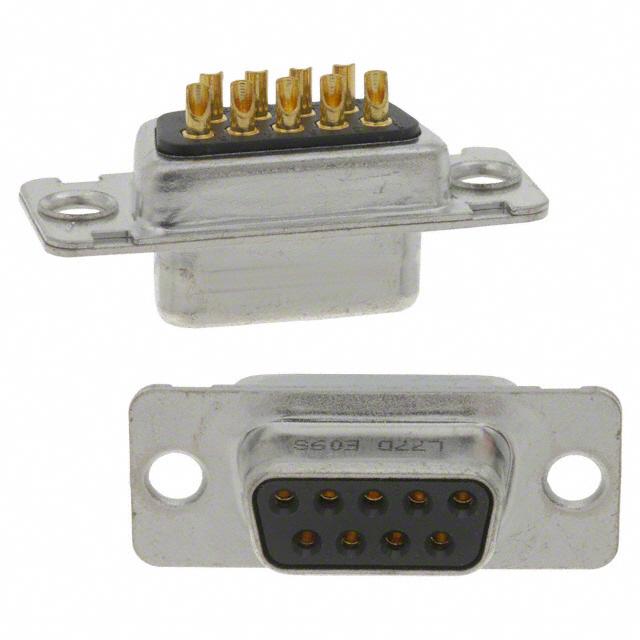
D-DF
D-Sub connectors - Screw-machined Contacts
Materials and Platings
Shells
Insulator
Rear insert
Boardlock
Screwlock
Contacts
Steel tinned with dimples on plug connector
Glass-filled thermoplastic, UL 94V-0
Brass, 3µm up to 5µm (118µ"up to 197µ")
tinned over nickel 2µm up to 3µm
(78µ" up to 118µ")
Tin plating 4µm up to 6µm
(157µ” up to 236µ”) over nickel 2µm up to 3µm
(78µ” up to 118µ”)
Brass, 6µm up to 10µm (236µ" up to 394µ")
tinned over nickel 2µm up to 3µm
(78µ" up to 118µ")
D: brass
DF: pin = brass
socket = copper alloy
Right angle version: full gold plating over 2µm to
3µm nickel
Straight version: full gold plating over 2µm up to
3µm (78µ” up to 118µ”) nickel
7.5A
300V AC/rms 50Hz
1000V AC/rms 50Hz for one minute
5000MΩ
D: 8.5mΩ max
DF: 5mΩ max
Climatic Data
Operating temperature D / DF: -55°C to + 125°C
Salt spray
48 hours
Humidity
D: 21 days (40˚C - 95% HR)
DF: 56 days (40˚C - 95% HR)
Mechanical Data
Mating and unmating force
Unit: kg ( lb)
No. of Cts
9 (size E)
15 (size A)
25 (size B)
37 (size C)
50 (size D)
Mate (max)
Unmate (min)
3.05 (6.74)
5.09 (11.24)
8.44 (18.66)
12.51 (27.65)
14.65 (32.38)
0.36 (0.79)
0.46 (1.01)
0.81 (1.8)
1.1 (2.47)
1.6 (3.56)
The machined contact provide
stability and reliability.
This series offers the broadest range
of termination options in the
Amphenol line.
Connectors
for industrial
and
telecom use
Electrical Data
Current rating
Voltage rating
Withstanding voltage
Insulation resistance
Contact resistance
Amphenol’s 17D and 17DF series
fixed contact D-Subminiature
connector is suitable for industrial
or telecom use.
• Medical
• Industrial
• Telecom
• Any industry standard
I / O connections
D-DF / E18
• Connectors according to MIL C24308 - NFC93425-HE5
DESCRIPTION
Specifications
APPLICATIONS
CHARACTERISTICS
FIXED MACHINED
CONTACT CONNECTOR
�F
1.50
10˚
H
A
B
B’
0.90
D’
D
E
J
OVERALL DIMENSIONS
Shell size dimensions
G
ø3.10
Shell
size
Contact
S
P
A
S
P
B
S
P
C
S
P
D
±0.25
(±.010)
B
0/-0.20
(0/-.008)
B‘
+0.20/0
(+.008/0)
C
D
±0.10
(±.004)
0/-0.25
(0/-.010)
16.8
(.661”) 25.0
30.7
(.984”) 8.0
(1.209”) 16.4
(.315”)
(.646”)
25.1
(.988”) 33.3
39.0
(1.311”) 8.0
(1.535”) 24.8
(.315”)
(.976”)
38.8
(1.528”) 47.0
52.9
(1.850”) 8.0
(2.083”) 38.5
(.315”)
(1.513”)
55.3
(2.177”) 63.5
69.2
(2.500”) 8.0
(2.724”) 54.9
(.315”)
(2.161”)
52.7
(2.075”) 61.1
66.8
(2.406”) 10.9
(2.630”) 52.5
(.429”)
(2.067”)
P
E
A
P: Pin
S: Socket
S
C
D‘
+0.25/0
(+.010/0)
8.2
(.323”)
8.2
(.323”)
8.2
(.323”)
8.2
(.323”)
11.0
(.433”)
E
±0.20
(±.008)
F
G
F‘
+0.05/-0.20 +0.10/-0.20 +0.10/-0.20
(+.002/-.008) (+.004/-.008) (+.004/-.008)
12.4
(.488”)
12.4
(.488”)
12.4
(.488”)
12.4
(.488”)
15.2
(.598”)
11.1
(.437)
11.1
(.437)
11.1
(.437)
11.1
(.437)
11.1
(.437)
10.9
(.429”)
10.9
(.429”)
11.0
(.433”)
11.0
(.433”)
11.0
(.433”)
6.2
(.244”)
6.2
(.244”)
6.2
(.244”)
6.2
(.244”)
6.2
(.244”)
G‘
±0.10
(±.004)
5.9
(.232”)
5.9
(.232”)
5.8
(.228”)
5.8
(.228”)
5.8
(.228”)
H
+0.10/-0.40
(+.004/-.016)
J
0/-0.50
(0/-.020)
19.4 11.0
(.764”) (.433”)
27.7 11.0
(1.091”) (.433”)
41.4 11.0
(1.630”) (.433”)
57.9 11.0
(2.280”) (.433”)
55.5 13.8
(2.185”) (.543”)
Panel cutouts
Optimal cutout for rear mounting
øG
B
A
B
C
D
A
10˚
G H
Rd Rading J
C
E
B
10˚
D
Shell
size
Standard cutout
A
Mounting
method
Front
Rear
Front
Rear
Front
Rear
Front
Rear
Front
Rear
A
±0.20
(±.008)
22.2
(.874”)
20.5
(.807”)
30.5
(1.201”)
28.8
(1.134”)
44.3
(1.744”)
42.5
(1.673”)
60.7
(2.390”)
59.1
(2.327”)
58.3
(2.295”)
56.3
(2.217”)
B
±0.20
(±.008)
11.1
(.437”)
10.2
(.402”)
15.3
(.602”)
14.4
(.567”)
22.1
(.870”)
21.3
(.839”)
30.4
(1.197”)
29.5
(1.161”)
29.2
(1.150”)
28.2
(1.110”)
C
F
D
R
D
±0.20
(±.008)
±0.20
(±.008)
25.0
(.984”)
12.5
(.492”)
33.3
(1.311”)
16.7
(.657”)
47.0
(1.850”)
23.5
(.925”)
63.5
(2.500”)
31.7
(1.248”)
61.1
(2.406”)
30.6
(1.205”)
Rd Rading J
C
E
±0.20
(±.008)
13.0
(.512”)
11.4
(.449”)
13.0
(.512”)
11.4
(.449”)
13.0
(.512”)
11.4
(.449”)
13.0
(.512”)
11.4
(.449”)
15.8
(.622”)
14.1
(.555”)
F
±0.20
(±.008)
6.5
(.256”)
5.7
(.224”)
6.5
(.256”)
5.7
(.224”)
6.5
(.256”)
5.7
(.224”)
6.5
(.256”)
5.7
(.224”)
7.9
(.311”)
7.1
(.280”)
G
E
H
±0.20
(±.008)
±0.20
(±.008)
3.0
(.118”)
1.5
(.059”)
3.0
(.118”)
1.5
(.059”)
3.0
(.118”)
1.5
(.059”)
3.0
(.118”)
1.5
(.059”)
3.0
(.118”)
1.5
(.059”)
J
±0.20
(±.008)
2.1
(.083”)
3.4
(.0134”)
2.1
(.083”)
3.4
(.0134”)
2.1
(.083”)
3.4
(.0134”)
2.1
(.083”)
3.4
(.0134”)
2.1
(.083”)
3.4
(.0134”)
2
�OVERALL DIMENSIONS
Termination
Right angle
MIL Footprint
without bracket:
2.84 (.112”)
2.84 (.112”)
ø1.02 (.040”)
9.3
(.366”)
8.1 (.319”)
9.3
(.366”)
8.1 (.319”)
ø0.6 (.024”)
C
A4
plastic bracket:
8.1 (.319”)
2.84 (.112”)
6.3
(.248”)
3
(.118”)
8.1 (.319”)
2.84 (.112”)
6.3
(.248”)
3
(.118”)
ø1.02
(.040”)
ø0.6 (.024”)
AJ3
AJ4
metal bracket:
14.99 (.59”)
50 contacts:
3
(.118”)
AM4B
8.1 (.319”)
2.84 (.112”)
D-DF / E18
A
AM4: A=13.2mm
AZ4: A=11.5mm
3
ø0.6 (.024”)
ø0.6 (.024”)
7.7
(.303”)
A
6.3 (.248”)
8.1 (.319”)
3
(.118”)
3
(.118”)
6.3 (.248”)
ø1.02 (.040”)
2.84 (.112”)
3.2
(.126”)
2.84 (.112”)
2.84 (.112”)
6.3 (.248”)
8.1 (.319”)
�European footprint
without bracket:
X
11.2
(.441”)
10.3
(.406”)
ø0.6 (.024”)
1AON: X=2.54mm
1BON: X=2.84mm
plastic bracket:
6.2 (.244”)
10.3 (.406”)
X
10.3 (.406”)
ø0.6 (.024”)
7.2
(.283”)
7.2
(.283”)
4
(.157”)
4
(.157”)
X
1APN: X=2.54mm
1BPN: X=2.84mm
ø0.6 (.024”)
1AUN: X=2.54mm
1BUN: X=2.84mm
metal bracket:
6.2 (.244”)
10.3 (.406”)
10.3 (.406”)
X
ø0.6 (.024”)
7.2
(.283”)
4
(.157”)
4
(.157”)
X
50 contacts:
ø0.6 (.024”)
1ATN: X=2.54mm
1BTN: X=2.84mm
4
(.157”)
1AMN: X=2.54mm
1BMN: X=2.84mm
8.6
(.339”)
7.2
(.283”)
TECHNICAL DATA
Termination
10.3 (.406”)
X
4
�TECHNICAL DATA
Termination
2.8 (.110”)
5.6 (.220”)
Solder Cup:
5.6 (.220”)
Wire Wrap:
L
termination
F179
F179A
Nb of wraps
L
2
9.6mm (.378”)
3
13mm (.512”)
termination
U
V
T
OL2
Ø
L
0.78/0.86
(.0.31”/.034”)
5.6 (.220”)
L
ø
1.52 (.060”) max
Straight PCB:
0.6mm (.024”)
3.2mm (.126”)
1.02mm (.040”)
2.4mm (.095”)
0.6mm (.024”)
4mm (.157”)
0.6mm (.024”)
5.5mm (.217”)
Grounding tabs:
For straight termination
RM5
for holes ø3.2 (.126”)
for holes ø3.2 (.126”)
RM8
RM6
D-DF / E18
FOR PCB 1.6
6.2 (.244”)
7.2
(.283”)
for holes ø3.2 (.126”)
7.2
(.283”)
M3 or #4-40
M3 or #4-40
5
For R/A termination
�TECHNICAL DATA
Panel mounting option
For straight and R/A termination
M3 or #4-40
float
3.6 (.141”)
ø3.1 (.122”)
3.4 (.134”)
ø2.2 (.086”)
Standard rivet 3.1mm
no digit
Float mounting
F
M3 or #4-40
front screwlock
Threaded rear insert
H/G
M3 or #4-40
removable screwlock
6.2 (.244”)
Fixed front female screwlock
VF / VFM
Removable female screwlock
VF2 / VFM2
Recommended PCB Layout
C
2 x ø3,2 (.126”)
F
D size
E,A,B,C size
X
X
2.74 (.108”) for size E,A
2.76 (.109”) for size B,C,D
0.9 (.035”) for U - T - OL2
and right angle termination
1.30 (.05”) for V termination
For straight PCB: X = 2.84mm (.112”)
MIL: X = 2.84mm (.112”)
For right angle PCB:
European: X = 2.54mm (.100”), 2.84mm in option
size E
size A
size B
size C
size D
C±0,1 (.004)
25 (.984)
33.3 (1.311)
47 (1.85)
63.5 (2.5)
61.1 (2.406)
F±0,05 (.002)
10.96 (.431)
19.18 (.755)
33.12 (1.304)
49.68 (1.956)
44.2 (1.74)
6
�D-DF / E18
7
HOW TO ORDER
How to order
�Amphenol IT & Communication Products
Block A3/A4, The 4th Industrial District of
Industrial Headquarters, Dong Keng Road
Gong Ming Town, Shen Zhen China
Fax:+86(0)755 2754 9955
Technical Support
Tel:+86(0)755 2717 7945
Info-dsub@amphenol.com.cn
http://www.dsubconnector.com
The information given in this document are as a guideline only. We reserve the right to modify our products in any way we deem necessary. Any duplication is prohibited, unless approved in writing.
Do not hesitate to contact us for further information
E13/B
NOTES
Memo
8
�
很抱歉,暂时无法提供与“L77DE09S”相匹配的价格&库存,您可以联系我们找货
免费人工找货