0
登录后你可以
  • 下载海量资料
  • 学习在线课程
  • 观看技术视频
  • 写文章/发帖/加入社区
会员中心
创作中心
发布
  • 发文章

  • 发资料

  • 发帖

  • 提问

  • 发视频

创作活动
NKA102C7R2C

NKA102C7R2C

  • 厂商:

    AMPHENOL(安费诺)

  • 封装:

    Bead

  • 描述:

    THERMISTOR NTC 500OHM 3977K BEAD

  • 详情介绍
  • 数据手册
  • 价格&库存
NKA102C7R2C 数据手册
NTC Type CR1 Harsh Environment Chip Thermistor Description NTC type CR1 are NK format chip thermistors on Sn coated Alloy 52 leads with a high performance acid and moisture resistant coating. Our NTC chip thermistors are ideal for harsh environment applications and high volume assembly. Features Applications • AEC Q200 Rev D Qualified • Automotive • Suitable for EGR, SCR, TMAP, OAT, HVAC & white goods applications • HVAC • Performance up to 190°C with excellent stability • Marine • Small body diameter • Aerospace • Fast response • Military • High thermal shock resistance • Industrial • Harsh environment fluids resistance • Healthcare • Water immersion • Flexible – coated leads can be formed • Insulation resistance to 1kV d.c. • Designed for accurate temperature measurement, control & compensation • Tight tolerances on resistance and B value • Available on bandolier to IEC 286-2 RoHS 2011/65/EC / REACH compliant Amphenol Advanced Sensors • White goods Type CR1 Specifications Options Specification Data Minimum operating temp. -40°C • Other resistance values and B values within the ranges shown Performance up to: 190°C Thermal time constant 15s (cooling) 2.4s (ambient change) • Alternative reference temperatures 0°C to 100°C Dissipation factor 2.2mW/K • Lead materials : Steel/Alloy 52 Mass 0.18g • Contact Amphenol for specific application requirements Packing 1000/box 2000/reel • Bulk packed or bandolier up to H1 = 48mm Coding: • Standard EGR Sensor - NKA202C2B2 • For CR1 Coating add Suffix C to Code See Table on page 4 for standard resistance values Typical Dimensions (mm) Bandolier, or Bulk 45max 29.5mm max 7 max 3 max 2.54 nom 3 max dia 0.4 ± 0.02 0.5 min 1 max Bandolier Schematic Products with 2.54mm Lead Spacing 2 Normal Feeding Direction Bandolier Specifications Item TOTAL BAND THICKNESS MAXIMUM BAND THICKNESS Including component lead/splices CARRIER TAPE WIDTH ADHESION TAPE WIDTH The hold down tape shall not protrude beyond either edge of the carrier tape POSITION OF ADHESION TAPE Gap between upper edges of carrier tape and hold-down tape Symbol Value (mm) t 0.7 ± 0.2 Tt 1.5 MAXIMUM W 18 + 1.0 / - 0.5 W0 6.0 MINIMUM W2 3.0 MAXIMUM SPROCKET HOLE POSITION W1 9.0 ± 0.5 SPROCKET HOLE DIAMETER D0 4.0 ± 0.2 PITCH OF COMPONENT P 12.7 ± 1.0 SPROCKET HOLE PITCH P0 12.7 ± 0.3 PITCH TOLERANCE OVER ANY 20 PITCHES ± 1.0 WIRE POSITION Distance between the ordinate and the first lead of the following component in the direction of unreeling or feeding. (Valid from upper edge of the tape to the seating plane) P1 5.08 ± 0.7 P2 6.35 ± 1.3 dp ±3 dh ±3 F 2.5 ± 0.5 d 0.4 ± 0.02 H 45 ±1 H1 48 max h 5 MAXIMUM l1 NO PROTRUSION PERMITTED For cut out components the length of the residual leads beyond the upper edge of the carrier tape measured from the abscissa L 12 Nom COMPONENT HEAD LENGTH A 5 max HOLE CENTRE TO COMPONENT CENTRE IN-PLANE COMPONENT DEVIATION Maximum deviation of the component body in the tape plane (from the nominal position) FRONT TO REAR DEVIATION The maximum lateral deviation of the component from the nominal position measured at the bottom centre of the component body. Maximum alignment deviation of the leads (valid from the upper edge of the tape to the seating plane) when dh is taken as zero, shall be 0.2mm. This dimension must remain in limits after the device has been cropped from the bandolier WIRE SPACING At upper edge of tape WIRE DIAMETER SEATING HEIGHT Distance between the abscissa and the seating plane of the component body with straight leads. HEAD HEIGHT Distance between the abscissa and the top of the component body WIRE PROTRUSION (Adhesive tape) Protrusion of wires beyond the lower side of the adhesive tape WIRE PROTRUSION (Carrier) Protrusion of wires beyond the lower side of the carrier tape CUT WIRE LENGTH EGR SENSOR Resistance B value 25/85°C Coating Packing NKA202C2B2 R100= 186.6Ω ± 2% 3540K ± 0.75% CR1 Bandoliered H1 = 45 ±1mm 3 NKA Standard Range Resistance Values (other values available upon request) R25 Ω Material System B Value 25/85°C K Maximum# Operating Temp. °C (°F) Code R25°C ± 1% Code R25°C ± 2% Code R25°C ± 3% Code R25°C ± 5% Code R25°C ± 10% 500 2 3540 ± 1% 170 (338) NKA501C2*1 NKA501C2*2 NKA501C2*3 NKA501C2*5 NKA501C2*10 500 2A 3627 ± 1% 170 (338) NKA501C2A*1 NKA501C2A*2 NKA501C2A*3 NKA501C2A*5 NKA501C2A*10 500 7 3977± 1% 170 (338) NKA501C7*1 NKA501C7*2 NKA501C7*3 NKA501C7*5 NKA501C7*10 1000 2 3540 ± 1% 170 (338) NKA102C2*1 NKA102C2*2 NKA102C2*3 NKA102C2*5 NKA102C2*10 1000 2A 3627 ± 1% 170 (338) NKA102C2A*1 NKA102C2A*2 NKA102C2A*3 NKA102C2A*5 NKA102C2A*10 1000 7 3977± 1% 170 (338) NKA102C7*1 NKA102C7*2 NKA102C7*3 NKA102C7*5 NKA102C7*10 2000 2 3540 ± 1% 170 (338) NKA202C2*1 NKA202C2*2 NKA202C2*3 NKA202C2*5 NKA202C2*10 2050 2 3540 ± 0.75% 170 (338) 2000 2A 3627 ± 1% 170 (338) NKA202C2A*1 NKA202C2A*2 NKA202C2B2 NKA202C2A*3 NKA202C2A*5 NKA202C2A*10 2000 7 3977± 1% 170 (338) NKA202C7*1 NKA202C7*2 NKA202C7*3 NKA202C7*5 NKA202C7*10 2700 1 3977 ± 0.75% 190 (374) NKA272C1*1 NKA272C1*2 NKA272C1*3 NKA272C1*5 NKA272C1*10 5000 4A 3435 ± 1% 170 (338) NKA502C4A*1 NKA502C4A*2 NKA502C4A*3 NKA502C4A*5 NKA502C4A*10 5000 1 3977 ± 0.75% 190 (374) NKA502C1*1 NKA502C1*2 NKA502C1*3 NKA502C1*5 NKA502C1*10 10000 4A 3435 ± 1% 170 (338) NKA103C4A*1 NKA103C4A*2 NKA103C4A*3 NKA103C4A*5 NKA103C4A*10 10000 5 3740 ± 1% 170 (338) NKA103C5*1 NKA103C5*2 NKA103C5*3 NKA103C5*5 NKA103C5*10 10000 1 3977 ± 0.75% 190 (374) NKA103C1*1 NKA103C1*2 NKA103C1*3 NKA103C1*5 NKA103C1*10 12000 5 3740 ± 1% 170 (338) NKA123C5*1 NKA123C5*2 NKA123C5*3 NKA123C5*5 NKA123C5*10 30000 8 3977± 1% 170 (338) NKA303C8*1 NKA303C8*2 NKA303C8*3 NKA303C8*5 NKA303C8*10 50000 8 3977± 1% 170 (338) NKA503C8*1 NKA503C8*2 NKA503C8*3 NKA503C8*5 NKA503C8*10 Replace * in the table codes shown above as follows: Loose-packed ............................................ R Bandoliered ............................................... B Note: Add Suffix C to Code for CR1 See separate tables for resistance - temperature data Amphenol Advanced Sensors www.amphenol-sensors.com © 2015 Amphenol Corporation. All Rights Reserved. Specifications are subject to change without notice. Other company names and product names used in this document are the registered trademarks or trademarks of their respective owners. AAS-920-645G - 06/2015
NKA102C7R2C
物料型号:NTC Type CR1

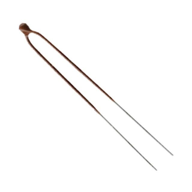
器件简介:CR1是NK格式的芯片热敏电阻,采用锡涂层的Alloy 52引脚,具有高性能的耐酸和耐湿涂层。这些热敏电阻非常适合恶劣环境应用和高容量组装。

特点: - 符合AEC Q200 Rev D标准 - 适用于EGR、SCR、TMAP、OAT、HVAC和白色家电应用 - 性能高达190°C,具有出色的稳定性 - 小型化体直径 - 快速响应 - 高热冲击抵抗 - 耐恶劣环境液体 - 可浸水 - 引脚可塑性 - 绝缘电阻高达1kV直流 - 设计用于精确的温度测量、控制和补偿 - 电阻和B值的严格公差 - 符合IEC 286-2、RoHS 2011/65/EC和REACH标准的带式包装

功能详解:CR1热敏电阻设计用于精确测量温度,控制和补偿,具有严格的电阻和B值公差。

应用信息:适用于汽车、HVAC、白色家电、海洋、航空航天、军事、工业和医疗保健领域。

封装信息:CR1热敏电阻的封装规格包括最小工作温度-40°C,性能高达190°C,热时间常数15秒(冷却)和2.4秒(环境变化),耗散因子2.2mW/K,质量0.18克,包装1000/盒或2000/卷。

引脚分配参数特性:文档中提供了详细的引脚分配图和规格表,包括总带宽、最大带宽、载体胶带宽度、定位胶带位置、链轮孔位置和直径、组件间距、引脚间距、引脚直径、组件高度、引脚突出长度等。

标准电阻值表提供了不同电阻值和B值的选项,以及其他参考温度范围、包装选项和引脚材料等选项。
NKA102C7R2C 价格&库存

很抱歉,暂时无法提供与“NKA102C7R2C”相匹配的价格&库存,您可以联系我们找货

免费人工找货