NTC Type CR1
Harsh Environment
Chip Thermistor
Description
NTC type CR1 are NK format chip thermistors on Sn coated Alloy 52 leads with a high performance acid
and moisture resistant coating. Our NTC chip thermistors are ideal for harsh environment applications and
high volume assembly.
Features
Applications
• AEC Q200 Rev D Qualified
• Automotive
• Suitable for EGR, SCR, TMAP, OAT, HVAC &
white goods applications
• HVAC
• Performance up to 190°C with excellent stability
• Marine
• Small body diameter
• Aerospace
• Fast response
• Military
• High thermal shock resistance
• Industrial
• Harsh environment fluids resistance
• Healthcare
• Water immersion
• Flexible – coated leads can be formed
• Insulation resistance to 1kV d.c.
• Designed for accurate temperature measurement,
control & compensation
• Tight tolerances on resistance and B value
• Available on bandolier to IEC 286-2 RoHS
2011/65/EC / REACH compliant
Amphenol
Advanced Sensors
• White goods
�Type CR1 Specifications
Options
Specification Data
Minimum operating temp. -40°C
• Other resistance values and B values within
the ranges shown
Performance up to:
190°C
Thermal time constant
15s (cooling)
2.4s (ambient change)
• Alternative reference temperatures 0°C to
100°C
Dissipation factor
2.2mW/K
• Lead materials : Steel/Alloy 52
Mass
0.18g
• Contact Amphenol for specific application
requirements
Packing
1000/box
2000/reel
• Bulk packed or bandolier up to H1 = 48mm
Coding:
• Standard EGR Sensor - NKA202C2B2
• For CR1 Coating add Suffix C to Code
See Table on page 4 for standard resistance values
Typical Dimensions (mm)
Bandolier, or Bulk 45max
29.5mm max
7 max
3 max
2.54 nom
3 max
dia 0.4 ± 0.02
0.5 min 1 max
Bandolier Schematic
Products with 2.54mm Lead Spacing
2
Normal Feeding Direction
�Bandolier Specifications
Item
TOTAL BAND THICKNESS
MAXIMUM BAND THICKNESS
Including component lead/splices
CARRIER TAPE WIDTH
ADHESION TAPE WIDTH
The hold down tape shall not protrude beyond either edge of the carrier tape
POSITION OF ADHESION TAPE
Gap between upper edges of carrier tape and hold-down tape
Symbol
Value (mm)
t
0.7 ± 0.2
Tt
1.5 MAXIMUM
W
18 + 1.0 / - 0.5
W0
6.0 MINIMUM
W2
3.0 MAXIMUM
SPROCKET HOLE POSITION
W1
9.0 ± 0.5
SPROCKET HOLE DIAMETER
D0
4.0 ± 0.2
PITCH OF COMPONENT
P
12.7 ± 1.0
SPROCKET HOLE PITCH
P0
12.7 ± 0.3
PITCH TOLERANCE OVER ANY 20 PITCHES
± 1.0
WIRE POSITION
Distance between the ordinate and the first lead of the following component in the
direction of unreeling or feeding. (Valid from upper edge of the tape to the seating
plane)
P1
5.08 ± 0.7
P2
6.35 ± 1.3
dp
±3
dh
±3
F
2.5 ± 0.5
d
0.4 ± 0.02
H
45 ±1
H1
48 max
h
5 MAXIMUM
l1
NO PROTRUSION
PERMITTED
For cut out components the length of the residual leads beyond the upper edge of the
carrier tape measured from the abscissa
L
12 Nom
COMPONENT HEAD LENGTH
A
5 max
HOLE CENTRE TO COMPONENT CENTRE
IN-PLANE COMPONENT DEVIATION
Maximum deviation of the component body in the tape plane (from the nominal position)
FRONT TO REAR DEVIATION
The maximum lateral deviation of the component from the nominal position measured at
the bottom centre of the component body. Maximum alignment deviation of the leads
(valid from the upper edge of the tape to the seating plane) when dh is taken as zero,
shall be 0.2mm. This dimension must remain in limits after the device has been cropped
from the bandolier
WIRE SPACING
At upper edge of tape
WIRE DIAMETER
SEATING HEIGHT
Distance between the abscissa and the seating plane of the component body with
straight leads.
HEAD HEIGHT
Distance between the abscissa and the top of the component body
WIRE PROTRUSION
(Adhesive tape)
Protrusion of wires beyond the lower side of the adhesive tape
WIRE PROTRUSION
(Carrier)
Protrusion of wires beyond the lower side of the carrier tape
CUT WIRE LENGTH
EGR SENSOR
Resistance
B value 25/85°C
Coating
Packing
NKA202C2B2
R100= 186.6Ω ± 2%
3540K ± 0.75%
CR1
Bandoliered H1 = 45 ±1mm
3
�NKA Standard Range Resistance Values
(other values available upon request)
R25
Ω
Material
System
B Value
25/85°C
K
Maximum#
Operating
Temp.
°C (°F)
Code
R25°C ± 1%
Code
R25°C ± 2%
Code
R25°C ± 3%
Code
R25°C ± 5%
Code
R25°C ± 10%
500
2
3540 ± 1%
170 (338)
NKA501C2*1
NKA501C2*2
NKA501C2*3
NKA501C2*5
NKA501C2*10
500
2A
3627 ± 1%
170 (338)
NKA501C2A*1
NKA501C2A*2
NKA501C2A*3
NKA501C2A*5
NKA501C2A*10
500
7
3977± 1%
170 (338)
NKA501C7*1
NKA501C7*2
NKA501C7*3
NKA501C7*5
NKA501C7*10
1000
2
3540 ± 1%
170 (338)
NKA102C2*1
NKA102C2*2
NKA102C2*3
NKA102C2*5
NKA102C2*10
1000
2A
3627 ± 1%
170 (338)
NKA102C2A*1
NKA102C2A*2
NKA102C2A*3
NKA102C2A*5
NKA102C2A*10
1000
7
3977± 1%
170 (338)
NKA102C7*1
NKA102C7*2
NKA102C7*3
NKA102C7*5
NKA102C7*10
2000
2
3540 ± 1%
170 (338)
NKA202C2*1
NKA202C2*2
NKA202C2*3
NKA202C2*5
NKA202C2*10
2050
2
3540 ± 0.75%
170 (338)
2000
2A
3627 ± 1%
170 (338)
NKA202C2A*1
NKA202C2A*2
NKA202C2B2
NKA202C2A*3
NKA202C2A*5
NKA202C2A*10
2000
7
3977± 1%
170 (338)
NKA202C7*1
NKA202C7*2
NKA202C7*3
NKA202C7*5
NKA202C7*10
2700
1
3977 ± 0.75%
190 (374)
NKA272C1*1
NKA272C1*2
NKA272C1*3
NKA272C1*5
NKA272C1*10
5000
4A
3435 ± 1%
170 (338)
NKA502C4A*1
NKA502C4A*2
NKA502C4A*3
NKA502C4A*5
NKA502C4A*10
5000
1
3977 ± 0.75%
190 (374)
NKA502C1*1
NKA502C1*2
NKA502C1*3
NKA502C1*5
NKA502C1*10
10000
4A
3435 ± 1%
170 (338)
NKA103C4A*1
NKA103C4A*2
NKA103C4A*3
NKA103C4A*5
NKA103C4A*10
10000
5
3740 ± 1%
170 (338)
NKA103C5*1
NKA103C5*2
NKA103C5*3
NKA103C5*5
NKA103C5*10
10000
1
3977 ± 0.75%
190 (374)
NKA103C1*1
NKA103C1*2
NKA103C1*3
NKA103C1*5
NKA103C1*10
12000
5
3740 ± 1%
170 (338)
NKA123C5*1
NKA123C5*2
NKA123C5*3
NKA123C5*5
NKA123C5*10
30000
8
3977± 1%
170 (338)
NKA303C8*1
NKA303C8*2
NKA303C8*3
NKA303C8*5
NKA303C8*10
50000
8
3977± 1%
170 (338)
NKA503C8*1
NKA503C8*2
NKA503C8*3
NKA503C8*5
NKA503C8*10
Replace * in the table codes shown above as follows:
Loose-packed ............................................ R
Bandoliered ............................................... B
Note: Add Suffix C to Code for CR1
See separate tables for resistance - temperature data
Amphenol
Advanced Sensors
www.amphenol-sensors.com
© 2015 Amphenol Corporation. All Rights Reserved. Specifications are subject to change without notice.
Other company names and product names used in this document are the registered trademarks or
trademarks of their respective owners.
AAS-920-645G - 06/2015
�
很抱歉,暂时无法提供与“NKA103C5R10C”相匹配的价格&库存,您可以联系我们找货
免费人工找货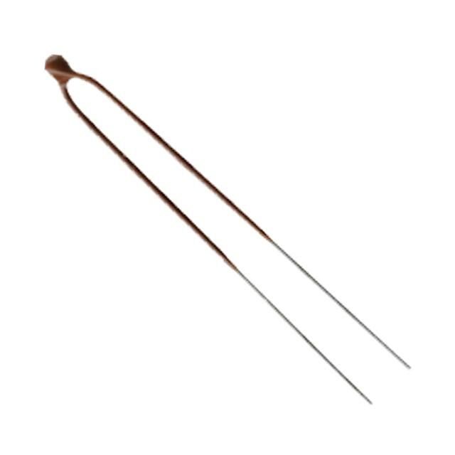


 工商网监
湘ICP备2023018690号
工商网监
湘ICP备2023018690号
