Reinforced Infocom Connectors for Harsh Environment
RJ Field - USB Field
Connecting to people + technology
www.rjfield.com
Amphenol
Rugged Digital Networks Solutions
�table of contents
Rugged Ethernet solutions
Field installable
RJFRB: plastic circular shell - reverse bayonet coupling..............................................................................................................................................10
RJF544: plastic circular shell - push pull coupling.........................................................................................................................................................13
RJFEZ: plastic rectangular shell - lever coupling............................................................................................................................................................15
RJF: metallic circular shell based on MIL-DTL-26482 H - bayonet coupling ......................................................................................................17
RJF special receptacles: inline receptacles and PC tails receptacles.......................................................................................................................20
NEW RJF receptacles and plug with 360° EMI backshells......................................................................................................................................................21
RJF transversally sealed receptacles...................................................................................................................................................................................22
RJF hermetic receptacles .......................................................................................................................................................................................................23
NEW RJF for big insulation wire up to 1.6 mm [0.062 inch]..................................................................................................................................................24
RJ Field receptacle with self closing cap ..........................................................................................................................................................................25
RJFTV: metallic circular shell based on MIL-DTL-38999 series III - thread coupling with anti-decoupling device................................26
Metallic self closing cap (SCC) for RJFTV square flange receptacle........................................................................................................................29
RJFTV receptacles and plugs with 360° EMI backshells...............................................................................................................................................30
RJFTV through bulkhead receptacles.................................................................................................................................................................................32
RJFTV stand off receptacles...................................................................................................................................................................................................33
NEW RJFTV transversally sealed receptacles..............................................................................................................................................................................36
NEW RJFTV hermetic receptacles...................................................................................................................................................................................................37
NEW RJFTV for big insulation wire up to 1.6 mm.....................................................................................................................................................................38
RJ45/M12 adaptor......................................................................................................................................................................................................................39
Special RJ45 adaptor for military & commercial aeronautics....................................................................................................................................40
High reliability Cat5E Ethernet cable and cordsets.......................................................................................................................................................41
W
E
High reliability Cat6 Ethernet cable and cordsets.........................................................................................................................................................42
N
NEW High reliability Cat6A Ethernet cable and cordsets......................................................................................................................................................43
NEW
Cable assemblies
RJ45/M12 railway cable solution..........................................................................................................................................................................................46
Jumper railway intercoach.....................................................................................................................................................................................................47
Rugged electronics
Military Ethernet media converter for harsh environment
NEW RES-GMC with Expanded Beam technology: military Ethernet media converter, fully MIL-STD compliant .......................................... 50
RES-GMC with butt joint fiber connector: military Ethernet media converter, fully MIL-STD compliant .................................................52
RJS-GMC with Expanded Beam Technology : military Ethernet Media Converter with industrial EMI compliancy ............................ 54
RES-GMC-1M-FORC: military Ethernet media converter with remote control, fully MIL-STD compliant ................................................ 56
NEW Military Ethernet switch for harsh environment, fully MIL-STD compliant
RES-SCE-AC-8US: unmanaged miniature portable Ethernet switch - 8 fast ports .......................................................................................... 58
RES-SCE-8MG: managed miniature portable Ethernet switch - 8 Gigabit ports . ......................................................................................... .. 60
RESMLAC-8US-CAPS: unmanaged military Ethernet switch, MIL-DTL-38999 connectors - 8 fast ports ................................................. 62
RJSMLAC-8UG-CAPS: unmanaged military Ethernet switch, RJFTV connectors - 8 Gigabit ports ........................................................... 64
RJSMLAC-8MG-CAPS: managed military Ethernet switch, RJFTV connectors - 8 Gigabit ports . .............................................................. 66
RESMLAC-8MG-CAPS: managed military Ethernet switch, MIL-DTL-38999 connectors - 8 Gigabit ports .............................................. 68
RESMLAC-8MG-CAPS F35: managed military Ethernet switch, MIL-DTL-38999 connectors - 8 Gigabit ports ...................................... 70
RESMLAC-28MG: managed military Ethernet switch - 24 Gigabit + 4 combo 10G ports ........................................................................... 72
Military Ethernet switch for harsh environment with industrial EMI compliancy
RJSML-8US1 and RJSML-8UG1: unmanaged military Ethernet switch, 8 fast or Gigabit ports.................................................................... 75
RJSML-8MF : managed military Ethernet switch - 8 fast ports ................................................................................................................................ 79
RJSML-MG7F3G : managed military Ethernet switch - 7 fast ports + 3 Gigabit ports ..................................................................................... 83
�Rugged USB solutions (USB3.0 & USB2.0)
Field installable
USB3.0
NEW USB3FTV (USB-A) ............................................................................................................................................................................................................................................................88
NEW USB3F TV transversally sealed receptacles ......................................................................................................................................................................92
NEW USB3F TV hermetic receptacles ............................................................................................................................................................................................95
NEW USB3 receptacle with self closing cap ...............................................................................................................................................................................96
NEW Metallic self closing cap (SCC) for USB3F TV square flange receptacles ...............................................................................................................97
NEW High reliability USB 3.0 cordsets ..........................................................................................................................................................................................98
USB2.0
USBFTV (USB-A) ...............................................................................................................................................................................................................................................................99
USBF TV transversally sealed receptacles .......................................................................................................................................................................102
USBF TV hermetic receptacles ............................................................................................................................................................................................104
USBFTV receptacles with 360° EMI backshells .............................................................................................................................................................105
USBF TV through bulkhead receptacles..........................................................................................................................................................................106
USBF TV stand off receptacles ............................................................................................................................................................................................107
USB 2.0 receptacle with self closing cap (SCC) ............................................................................................................................................................108
Metallic self closing cap (SCC) for USBF TV square flange receptacles ................................................................................................................110
High reliability USB 2.0 cordsets ........................................................................................................................................................................................111
USBF SC - Quick release series ...........................................................................................................................................................................................112
USBBF TV (USB-B) ....................................................................................................................................................................................................................114
USBBF TV stand off receptacles .........................................................................................................................................................................................116
USBBF TV transversally sealed receptacles ....................................................................................................................................................................118
USBB receptacle with self closing cap .............................................................................................................................................................................120
Metallic self closing cap (SCC) for USBB square flange receptacles .....................................................................................................................121
NEW Special USB adaptor for Military & Commercial Aeronautics .................................................................................................................................122
Cable assemblies
USB-A plastic & neoprene solutions with self closing cap (SCC).............................................................................................................................124
USB-B Field plastic - Overmolded cordset plug.............................................................................................................................................................127
Rugged Electronics
NEW Reinforced USB3FTV memory keys....................................................................................................................................................................................130
NEW Reinforced USB amplifier.......................................................................................................................................................................................................131
ATEX Solutions
RJFTVX, USBFTVX, RJ11FTVX - RJ45, USB, RJ11/12 explosion proof solutions for Zone 2.............................................................................134
Other Rugged solutions
Field installable
FWFTV: metallic circular shell based on MIL-DTL-38999 series III - thread coupling with anti-decoupling device.............................142
IEEE1394 receptacle with self closing cap ......................................................................................................................................................................145
RJ11F: metallic circular shell based on MIL-DTL-26482 H - bayonet coupling...................................................................................................146
Special RJ11 adaptor for Military & Commercial Aeronautics..................................................................................................................................148
MTRJF TV: fiber optic solution - metallic circular shell based on MIL-DTL-38999 series III ...........................................................................150
LC Field: fiber optic solution - metallic circular shell based on MIL-DTL-38999 series III...............................................................................152
Glossary
.................................................................................................................................................................................................................................154
�RUGGED ETHERNET SOLUTION SELECTION GUIDE
Connectors
Series
Indust.
Ethernet
Spec.
RJF RB
Coupling
Mechanism
Shape
Material
Specification
Prime Market
Page
Reverse
Bayonet
Circular
Plastic
N/A
Industrial
& Telecom
10
RJF544
IEC 60603-7
variant 12
Push Pull
Circular
Plastic
N/A
Industrial
& Telecom
13
RJF EZ
IEC 60603-7
variant 13
Lever
Rectangular
Plastic
N/A
Industrial
& Telecom
15
RJF
IEC 60603-7
variant 11
Bayonet
Circular
Metal
MIL-DTL-26482
Industrial
Mil/Aero
17
RJF in line recepatcles & IEC 60603-7
variant 11
PC tails receptacles
Bayonet
Circular
Metal
MIL-DTL-26482
Industrial
Mil/Aero
20
RJF receptacles & plugs
with 360° EMI
backshells
Bayonet
Circular
Metal
MIL-DTL-26482
Industrial
Mil/Aero
21
D
RJF transversally sealed
receptacles
Bayonet
Circular
Metal
MIL-DTL-26482
Mil/Aero
& Industrial
22
I
RJF hermetic
receptacles
Bayonet
Circular
Metal
MIL-DTL-26482
Mil/Aero
& Industrial
23
RJF for big insulation
wire up to 1.6mm
[0.062 inch]
Bayonet
Circular
Metal
MIL-DTL-26482
Industrial
Mil/Aero
24
RJFTV
Thread
Circular
Metal
MIL-DTL-38999
Series III
Mil/Aero
& Rail Mass
Transit
26
RJF TV receptacles &
plugs with 360° EMI
backshells
Thread
Circular
Metal
MIL-DTL-38999
Series III
Mil/Aero
& Rail Mass
Transit
30
RJF TV through
bulkhead receptacles
Thread
Circular
Metal
MIL-DTL-38999
Series III
Mil/Aero
& Rail Mass
Transit
32
RJF TV stand off
receptacles
Thread
Circular
Metal
MIL-DTL-38999
Series III
Mil/Aero
& Rail Mass
Transit
33
RJFTV transversally
sealed receptacles
Bayonet
or Thread
Circular
Metal
MIL-DTL-38999
Series III
Mil/Aero
& Industrial
36
RJFTV hermetic
receptacles
Bayonet
or Thread
Circular
Metal
MIL-DTL-38999
Series III
Mil/Aero
& Industrial
37
RJF TV for big insulation
wireup to 1.6 mm
Bayonet
or Thread
Circular
Metal
MIL-DTL-38999
Series III
Mil/Aero
38
RJ45/M12 adaptors
Circular
Metal
Industrial
& Rail Mass
Transit
39
Special RJ45 adaptor for
Military & Commercial
Aeronautics
Circular
Metal
Industrial
& Rail Mass
Transit
40
F
I
NEW
E
L
N
NEW
S
T
A
L
L
A
B
L
E
NEW
NEW
NEW
�F
I
E
L
D
Cables
I
N
S
T
A
L NEW
L
A
B NEW
L
E
Series
C
A
B
L
E
Connectors
G
G
E
Material
Specification
Prime Market
Page
Mil/Aero & Industrial
41
High reliability Cat 6
cable and cordsets
Mil/Aero & Industrial
42
High reliability Cat 6A
cable and cordsets
Mil/Aero & Industrial
43
Coupling
Mechanism
Shape
Material
RJ45/M12
Railway cable solution
Bayonet
Circular
Metal
Jumper
Thread
Circular
Series
Indust.
Ethernet Spec.
Metal
Specification
Prime Market
Page
MIL-DTL-26482
Industrial
& Rail Mass
Transit
46
MIL-DTL-38999
Series III
Rail Mass
Transit
47
Sealing
Type
# of ports
Prime Market
Page
RES-GMC Media converter
with Expanded Beam Tech.
IP67/68
Unmanaged
2 Gb ports
Mil/Aero
50
RES-GMC Media converter
with Butt Joint Fiber connect.
IP67/68
Unmanaged
2 or 4 Gb ports
Mil/Aero
52
RJS-GMC with Expanded Beam
Technology
IP67/68
Unmanaged
2 or 4 or 8 Gb ports
Mil/Aero
54
RES-GMC-1M-FORC Media
converter with Remote Control
IP67/68
Unmanaged
1 Gb port
+
1 Fiber port
Mil/Aero
56
RES-SCE-AC-8US miniature
portable switch
IP67/68
Unmanaged
8 Fast ports
Mil/Aero
58
RES-SCE-AC-8MG miniature
portable switch
IP67/68
Managed
8 Gb ports
Mil/Aero
60
RESMLAC-8US-CAPS military
Ethernet switch
MIL-DTL-38999 connectors
IP67/68
Unmanaged
8 Fast ports
Mil/Aero
62
RJSMLAC-8UG-CAPS military
Ethernet switch
MIL-DTL-38999 connectors
IP67/68
Unmanaged
8 Gb ports
Mil/Aero
64
NEW
RJSMLAC-8MG-CAPS military
Ethernet switch
RJFTV connectors
IP67/68
Managed
8 Gb ports
Mil/Aero
66
NEW
RESMLAC-8MG-CAPS military
Ethernet switch
MIL-DTL-38999 connectors
IP67/68
Managed
8 Gb ports
Mil/Aero
68
NEW
RESMLAC-8MG-CAPS-F35
military Ethernet switch
MIL-DTL-38999 connectors
IP67/68
Managed
8 Gb ports
Mil/Aero
70
RESMLAC-28MG military
Ethernet switch
IP67/68
Managed
24 Gb + 4 combo 10G ports
Mil/Aero
72
RJSML-8US1 & RJSML-8UG1
military Ethernet switch
IP67/68
Unmanaged
8 Gb ports
Mil/Aero
73
RJSML-MG7F3G military
Ethernet switch
IP67/68
Managed
7 fast + 3 Gb ports
Mil/Aero
77
NEW
U
Shape
Series
NEW
R
Coupling
Mechanism
High reliability Cat 5E
cable and cordsets
Connectors
A
S NEW
S
E
M
B
L NEW
I
E
S
Indust.
Ethernet Spec.
NEW
NEW
NEW
D
NEW
E
L
E
C
NEW
NEW
T
R
O
N
I
C
S
�RUGGED USB SOLUTION SELECTION GUIDE
Connectors
NEW
NEW
NEW
Series
Coupling
Mechanism
Shape
Material
Specification
Prime Market
Page
USB3FTV (USB-A)
Thread
Circular
Metal
MIL-DTL-38999
Series III
Mil/Aero, Rail Mass Transit
& Industrial
81
USB3F TV transversally
sealed receptacles
Thread
Circular
Metal
MIL-DTL-38999
Series III
Mil/Aero, Rail Mass Transit
& Industrial
86
USB3F TV hermetic
receptacles
Thread
Circular
Metal
MIL-DTL-38999
Series III
Mil/Aero & Industrial
89
Mil/Aero, Rail Mass Transit
& Industrial
92
NEW
F
High reliability
USB 3.0 Cordsets
I
E
USBFTV (USB-A)
Thread
Circular
Metal
MIL-DTL-38999
Series III
Mil/Aero, Rail Mass Transit
& Industrial
93
USBF TV transversally
sealed receptacles
Thread
Circular
Metal
MIL-DTL-38999
Series III
Mil/Aero, Rail Mass Transit
& Industrial
96
USBF TV hermetic
receptacles
Thread
Circular
Metal
MIL-DTL-38999
Series III
Mil/Aero & Industrial
98
USBF TV special
receptacles with 360° EMI
backshells
Thread
Circular
Metal
MIL-DTL-38999
Series III
Mil/Aero, Rail Mass Transit
& Industrial
99
Special USB through
bulkhead receptacles
Thread
Circular
Metal
MIL-DTL-38999
Series III
MIl/Aero & Industrial
100
USBF TV stand off
receptacles
Thread
Circular
Metal
MIL-DTL-38999
Series III
Mil/Aero, Rail Mass transit
& Industrial
101
Mil/Aero, Rail Mass Transit
& Industrial
105
L
D
I
N
S
T
A
L
L
A
B
L
E
High reliability
USB 2.0 Cordsets
USBF SC
Quick release series
Spring
Release
Circular
Metal
N/A
Mil/Aero & Industrial
106
USBBF TV (USB-B)
Thread
Circula
Metal
MIL-DTL-38999
Series III
Mil/Aero, Rail Mass Transit
& Industrial
108
USBBF TV stand off
receptacles
Thread
Circular
Metal
MIL-DTL-38999 Mil/Aero, Rail Mass Transit
Series III
& Industrial
111
USBBF TV transversally
sealed receptacles
Thread
Circular
Metal
MIL-DTL-38999
Series III
Mil/Aero, Rail Mass Transit
& Industrial
113
Special USB adaptor
for Military & Commercial
Aeronautics
Circular
Metal
Aeronautic
116
�Connectors
A
S
S
E
M
B
L
I
E
S
C
A
B
L
E
R
U
G
G
E
D
Coupling
Series
Mechanism
USB-A plastic
with Self Closing Cap
E
W
L NE
E
C
T
R NEW
O
N
I
C
S
Shape
Material
Specification
Prime Market
Page
Circular
Plastic
N/A
Industrial & Telecom
118
USB B Field
Plastic shell
Overmolded cordset plug
Thread
Circular
Plastic
N/A
Industrial & Telecom
121
Reinforced
USB3FTV & USB 2.0
Memory Keys
Thread
Circular
Metal
MIL-DTL-38999
Series III
Mil/Aero & industrial
124
Reinforced
USB 2.0 amplifier
Thread
Circular
Metal
MIL-DTL-38999
Mil/Aero & Industrial
Series III
125
RUGGED ATEX ZONE 2 SOLUTION GUIDE
R
U
G
G
E
D
E
L
E
C
T
R
O
N
I
C
S
Connectors
Series
RJFTVX, USBFTVX
RJ11FTVX
Coupling mechanism
Shape
IP68
Material
Specification
Metal
Prime Market
Page
Factory Automation,
Video, Oil & Gaz
128
OTHER RUGGED SOLUTIONS
Connectors
Series
Coupling Mechanism
Shape
Material
Specification
Prime Market
Page
FWFTV (FireWire)
Thread
Circular
Metal
MIL-DTL-38999
Series III
Mil/Aero & Video
136
RJ11F (RJ11)
Bayonet
Circular
Metal
MIL-C-26482
MIL/Aero & Industrial
140
Circular
Metal
Aeronautic
142
F
I
E
L
D
I
N
S
T
NEW
Special RJ11 adaptor
for Military &
Commercial
Aeronautics
A
L
L
MTRJFTV (MTRJ)
Fiber optic solution
Thread
Circular
Metal
MIL-DTL-38999
Series III
Mil/Aero & Rail Mass Transit
141
LC Field
Fiber optic solution
Thread
Circular
Metal
MIL-DTL-38999
Series III
Mil/Aero & Rail Mass Transit
146
A
B
L
E
�NOTES
..............................................................................................................................................................................................................................................................................................
..............................................................................................................................................................................................................................................................................................
..............................................................................................................................................................................................................................................................................................
..............................................................................................................................................................................................................................................................................................
..............................................................................................................................................................................................................................................................................................
..............................................................................................................................................................................................................................................................................................
..............................................................................................................................................................................................................................................................................................
..............................................................................................................................................................................................................................................................................................
..............................................................................................................................................................................................................................................................................................
..............................................................................................................................................................................................................................................................................................
..............................................................................................................................................................................................................................................................................................
..............................................................................................................................................................................................................................................................................................
..............................................................................................................................................................................................................................................................................................
..............................................................................................................................................................................................................................................................................................
Amphenol
..............................................................................................................................................................................................................................................................................................
..............................................................................................................................................................................................................................................................................................
..............................................................................................................................................................................................................................................................................................
..............................................................................................................................................................................................................................................................................................
..............................................................................................................................................................................................................................................................................................
..............................................................................................................................................................................................................................................................................................
..............................................................................................................................................................................................................................................................................................
..............................................................................................................................................................................................................................................................................................
..............................................................................................................................................................................................................................................................................................
..............................................................................................................................................................................................................................................................................................
8
8
�Rugged Ethernet Solutions
Field installable
RJF RB: plastic circular shell - reverse bayonet coupling ..............................................................................................................................................
10
RJF544: plastic circular shell - push pull coupling ...............................................................................................................................
13
RJF EZ: plastic rectangular shell - lever coupling ................................................................................................................................
15
RJF: metallic circular shell based on MIL-DTL-26482 H - bayonet coupling ............................................................................... 17
RJF special receptacles: inline receptacles & PC tails receptacles .................................................................................................. 20
NEW RJF receptacles & plugs with 360° EMI backshells ...............................................................................................................................
21
NEW RJF transversally sealed receptacles...........................................................................................................................................................
22
Amphenol
table of contents
RJF hermetic receptacles ............................................................................................................................................................................... 23
RJF for big insulation wire up to 1.6 mm [0.062 inch] ........................................................................................................................ 24
Self Closing Cap (SCC) for RJ Field receptacles ..................................................................................................................................... 25
RJF TV: metallic circular shell based on MIL-DTL-38999 series III - thread coupling with anti-decoupling device .....
26
Metallic self closing cap (SCC) for RJFTV square flange receptacles.............................................................................................. 29
RJF TV receptacles and plugs with 360° EMI backshells .................................................................................................................... 30
RJF TV through bulkhead receptacles ...................................................................................................................................................... 32
RJF TV stand off receptacles .........................................................................................................................................................................
33
NEW RJF TV transversally sealed receptacles ...................................................................................................................................................
NEW RJF TV hermetic receptacles ........................................................................................................................................................................
36
37
NEW RJF TV for big insulation wire up to 1.6 mm ...........................................................................................................................................
38
RJ45/M12 adaptators ...................................................................................................................................................................................... 39
Special RJ45 adaptators for Military & Commercial Aeronautics ....................................................................................................
40
High reliability Cat 5E Ethernet cable & cordsets .................................................................................................................................
41
NEW High reliability Cat 6 Ethernet cable & cordsets ...................................................................................................................................
42
NEW High reliability Cat 6A Ethernet cable & cordsets ................................................................................................................................
43
9
�ROHS
compliant
RJF RB
Ethernet connection system for harsh environment – Industrial Ethernet
RJFRB allows you to use an Ethernet Class D / Cat 5e and Class E / Cat 6
connection for 10 BaseT, 100 BaseTX or 1000 BaseT networks in harsh
environments.
With the patented RJStop® system you can use a standard RJ45
cordset in a protective composite plug which will protect it from
shocks, dust and fluids.
No hazardous on-field cabling and grounding!
Applications
n
Telecom equipments
Main characteristics
n
Special machines
n
Sealed against fluids and dust (IP68)
n
Shock, vibration and traction resistant
n
No cabling operation in field, no tools required
n
Reverse bayonet coupling
n
RJ45 cordset retention in the plug: 70 N in the axis
n
Mating cycles: 500 min
n
Compatible with cable diameter from 5,5 mm [0.216 in] to 7 mm [0.275 in]
n
Motion control
Environmental protection
n
Video control
n
Robotics
n Industrial process control
n
CNC machines
Data transmission
n
Sealing: IP68
n
Salt spray > 1000 h
n
Fire retardant / Low smoke: UL94 V0 and NFF 16102, DIN 5510-2
n
Operating temperature: - 40°C / +85°C
Amphenol
10 BaseT, 100 BaseTX and 1000 BaseT networks
Cat 5e per TIA/EIA 568B and ClassD per ISO/IEC
11801
Cat6 per TIA/EIA 568B and ClassE per ISO/IEC 11801
Part number code
RJF RB
Shell type
6: composite reverse bayonet plug, plastic gland
7: composite jam nut receptacle
Back terminations (for receptacles only)
1: female RJ45
1RA: right angle female RJ45
2: RJ45 Cordset
3U: IDC cat6 - unshielded
3F: IDC cat6 - partial shielding
3S: IDC cat6 - 100% shielded
5: straight PCB
Cordset length (for receptacles with “2” back termination only)
03 100BTX: 0.3m [11.81 inches]
05 100BTX: 0.5m [19.68 inches]
10 100BTX: 1m [39.37 inches]
15 100BTX: 1.5m [59.05 inches]
Remark: cabling configuration 100 BTX = 568B (Ethernet specification)
10
Examples:
- Plug: RJF RB 6
- Receptacle, female RJ45 Back termination: RJF RB 71
- Receptacle, right angle female RJ45 back termination: RJF RB 71RA
- Receptacle, 1,5m [59.05”] RJ45 cordset termination: RJF RB 72 15 100BTX
7
1RA
�Plug
n
Type 6 shell with plastic gland
RJF RB 6
Receptacles
n
Type 1: female RJ45
(front mounting)
Panel Drilling
RJF RB 71
n
T�
ype 1RA: right angle female RJ45
(front mounting)
Panel Drilling
Amphenol
RJFRB71RA
n
Type 2: RJ45 cordset
(front mounting)
Panel Drilling
RJFRB72XX 100BTX
(XX=03, 05, 10 or 15 - see
part number code page 10)
n
Type 3: IDC CAT 6 termination
(rear mounting)
Unshielded: RJF RB 73U
Partial shielding RJF RB 73F
Panel Drilling
Shielded: RJFRB73S
11
�n
Straight PCB termination receptacle:
(rear mounting)
Panel Drilling
Part number: RJF RB 75
IMPORTANT NOTE
PCB drilling RJFRB
The customer’s PCB design will
determine the receptacle category.
Assembly instructions
Amphenol
1
2
3
4
5
6
7
8
Accessories
n IP68 Dust caps
RJF RB C7
RJF RB C75
Cap for receptacles RJFRB71 / 71RA / 72xxx
12
3
3
2
3
Cap for receptacles RJFRB75 and RJFRB73x
4
4
3
2
�ROHS
compliant
RJF 544
Ethernet connection system for harsh environment – Industrial Ethernet
RJF544 allows you to use an Ethernet Class D / Cat 5e connection for
10 BaseT, 100 Base TX or 1000 BaseT networks in harsh environments.
With the patented RJStop® system you can use a standard RJ45
cordset in a protective composite plug which will protect it from
shocks, dust and fluids.
No hazardous on-field cabling and grounding !
Main characteristics
Applications
n
Compliant with IEC 60603-7 variante 12
n
Shock, vibration and traction resistant
n No cabling operation in field and no tools required
n
Sealed against fluids and dust (IP68)
n
Quick push pull coupling
n RJ45 cordset retention in the plug: 100 N in the axis
n Mating cycles: 500 min
n
Improved EMI Protection
n
C
�ompatible with cable diameter from 6 mm [0.236 in] to 13 mm [0.512 in]
n Telecom equipment
n Video control
n Robotics
n Industrial process control
n CNC machines
n Special machines
n Motion control
n Tele-maintenance
Data transmission
10 BaseT, 100 BaseTX and 1000 BaseT networks
Cat 5e per TIA/EIA 568B and ClassD per ISO/IEC
11801
Environmental protection
n
Sealing: IP68
n Salt spray > 1000 h
n Fire retardant / Low smoke: UL94 V0 and NFF 16102, DIN 5510-2
n Vibrations: 10 – 500 Hz, 10 g, 3 axes: no discontinuity > 10 nano s.
n Operating temperature: - 40°C / +85°C
Amphenol
NEW
Now available with tranversal sealing*
*Seald in unmated condition
Part number code
RJF 544
2
2
03 100BTX
Shell type
6: composite push pull plug, plastic gland
2: composite square flange receptacle
2S: composite square flange receptacle transversally sealed
2M: metallized (Ni) composite square flange receptacle
2SM: metallized (Ni) composite square flange receptacle transversally sealed
Back terminations (for receptacles only)
1: female RJ45
1RA: right angle female RJ45
2: RJ45 cordset
Cordset length (for receptacles with “2” back termination only) - Other lengths are available on demand
03 100BTX: 0.3 meters [11.81 inches]
05 100BTX: 0.5 meters [19.68 inches]
10 100BTX: 1 meter [39.37 inches]
15 100BTX: 1.5 meters [59.05 inches]
00: 8 tinned holes at the rear of the PCB to solder the cable
Remark: cabling configuration 100 BTX = 568B (Ethernet specification)
Examples:
- Plug: RJF 544 6
- Square flange receptacle, female RJ45 back termination: RJF 544 21
- Metallized square flange receptacle, female RJ45 back termination: RJF 544 2M 1
- Square flange receptacle, 1,5m [59.05”] 100 BTX cordset termination: RJF 544 22 15 100BTX
- Square flange receptacle, solder termination: RJF 544 22 00
- Transversally sealed receptacle female RJ45 back termination: RJF544 2S1
13
�Plug
n
Type 6 shell with plastic gland
RJF 544 6
Receptacle
n
Type 2S/2M/2SM shell: square flange receptacle with 4 mounting holes
RJF 544 2x 1 RA
RJF 544 2x 1
Amphenol
Back terminations
Panel Drilling
Type1:
RJ45
Type 1:female
Female
RJ45
Type
1:
Female
RJ45
Type1RA:
right
female
RJ45
Type
2: RJ45
Cordset
Type
1:angle
Female
RJ45
Type
Cordset
Type2:
Type
2RJ45
- 00:cordset
Solder – 8 tinned holes
Type 2:
2: RJ45
RJ45
Cordset
Notes: type 2 without RJ45 plug at the end of the cable is also available: consult factory
Accessories
n �Rubber IP68 receptacle cap
p/n RJF 544BESC
n �Panel gasket
p/n RJF 544 02JE
n
Panel gasket (thickness: 0.6mm [.039]): p/n RJF 544 02 JE
n
Plug Insert removal tool: p/n 5440 OT 02
14
n IP68 caps for plug
p/n 544 02 BM
Type
2
Solder
–
holes
2 - 00:
solder
8 tinned
holes
TypeType
2 -- 00:
00:
Solder
–8
8- tinned
tinned
holes
�ROHS
compliant
RJF EZ
Ethernet connection system for harsh environment – Industrial Ethernet
RJFEZ allows you to use an Ethernet Class D / Cat. 5e connection for
10 BaseT,100 BaseTX or 1000 BaseT networks in harsh environments.
With the patented RJStop® system you can use a standard RJ45
cordset in a protective composite plug which will protect it from
shocks, dust and fluids.
No hazardous on-field cabling and grounding!
Applications
n
Telecom equipment
n
Video control
n
Robotics
n
Industrial process control
n
CNC machines
n
Special machines
n
Motion control
n
Tele-maintenance
Main characteristics
n Compliant with IEC 60603-7 variante 13
n
Sealed against fluids and dust (IP68)
n
Shock, vibration and traction resistant
n
No cabling operation in field and no tools required
n
Quick lever coupling
n
RJ45 cordset retention in the plug: 70 N in the axis
n
Mating cycles: 500 min
n
C
�ompatible with cable diameter from 5,5 mm [0.216 in] to 7 mm [0.275 in]
Environmental protection
10 BaseT, 100 BaseTX and 1000 BaseT networks
Cat 5e per TIA/EIA 568B and ClassD per ISO/IEC
11801
n
Sealing: IP68
n
Salt spray > 1000 h
n
Fire retardant / Low smoke: UL94 V0 and NFF 16102, DIN 5510-2
n
Operating temperature: - 40°C / +85°C
Part number code
RJF EZ
2
2
03 100BTX
Amphenol
Data transmission
Shell type
6: composite lever plug, plastic gland
2: composite square flange receptacle
Back terminations (for receptacles only)
1: female RJ45
2: RJ45 cordset
Cordset length (for receptacles with “2” back termination only)
03 100BTX: 0.3m [11.81 inches]
05 100BTX: 0.5m [19.68 inches]
10 100BTX: 1m [39.37 inches]
15 100BTX: 1.5m [59.05 inches]
Remark: Cabling configuration 100 BTX = 568B (Ethernet specification)
Examples:
- Plug: RJF EZ 6
- Receptacle, female RJ45 back termination: RJF EZ 21
- Receptacle, 1,5m [59.05”] 100 BTX cordset termination: RJF EZ 22 15 100BTX
15
�Plug
Receptacles
Panel Drilling
Back terminations
Amphenol
TypeType
1: Female
RJ45
1: female RJ45
Type
RJ45
Cordset
Type 2:2:RJ45
cordset
Notes: type 2 without RJ45 plug at the end of the cable is also available: consult factory
Assembly instructions
Accessories
n �IP68 dust caps
For plugs: not available
For receptacles: RJF EZ BE
16
n �Panel gasket
Thickness: 1 mm [.039]
Part No. RJF EZ JE
�ROHS
compliant
N&B
RJF
Ethernet connection system for harsh environment – Industrial Ethernet
RJF allows you to use an Ethernet Class D / Cat. 5e connection for 10
BaseT,100 BaseTX or 1000 BaseT networks in harsh environments.
With the patented RJStop®system you can use a standard RJ45 cordset
in a metallic plug which will protect it from shocks, dust and fluids.
No hazardous on-field cabling and grounding!
Main characteristics
Data transmission
10 BaseT, 100 BaseTX and 1000 BaseT networks
Cat 5e per TIA/EIA 568B and ClassD per ISO/IEC
11801
Environmental protection
n
Sealing: IP68
n Salt spray: 48 h with nickel plating
> 96 h with black coating
< 500 h with olive drab cadmium
n Fire retardant/Low smoke: UL94 V0 and NF F 16 101 & 16 102
n Vibrations: 10-500Hz, 10g, 3 axes: no discontinuity >10 nano s
n �Shocks: IK06 ►weight of 250 g drop from 40cm
[15.75 in] onto connectors (mated pair)
n Humidity: 21 days, 43°C, 98% humidity
n Temperature range: -40°C / +85°C
n Storage temperature:
Part number code
RJF
2
2
B
03 100BTX
Amphenol
Applications
n Robotics
n Industrial process control
n CNC machines
n Special machines
n Oil & Gas
n Motion control
n �Data acquisition and transmission in harsh
environment
n Tele-maintenance
n Compliant with IEC 60603-7 variante 11
n
Bayonet coupling (“Audible & Visual” coupling signal )
n �Robust metallic shells based on MIL-DTL-26482 H - Shell size 18
n RJ45 cordset retention in the plug: 100 N in the axis
n Mating cycles: 500 min
n Sealed against fluids and dust (IP68)
n Shock, vibration and traction resistant
n No cabling operation in field and no tools required
n Mechanical coding / polarization (4 positions)
n
C
�ompatible with cable diameter from 6 mm [0.236 in] to 13 mm [0.512 in]
For smaller diameters, please consult us.
Shell type
6: plug, plastic gland
6M: plug, metal gland
2: square flange receptacle
2PE: square flange receptacle, IP68 backshell, plastic gland
2PEM: square flange receptacle, IP68 backshell, metal gland
7: jam nut receptacle
7PE: jam nut receptacle, IP68 backshell, plastic gland
7PEM: jam nut receptacle, IP68 backshell, metal gland
Nota: also available a transversally sealed receptacle (unmated) ►see page 22
Back terminations (for receptacles only)
1: female RJ45
1RA: right angle female RJ45
2: RJ45 cordset
Shell finishes
B: black Coating - ROHS compliant
N: nickel - ROHS compliant
G: olive drab cadmium
Nota: for N, G, ZN the inserts are metallized.
ZN: aluminium shell - black zinc nickel plating - ROHS compliant
Cordset length (for receptacles with “2” back termination only) - Other lengths are available on demand
03 100 BTX: 0.3m [11.81 inches]
00: 8 tinned holes at the rear of the PCB to solder the cable
05 100 BTX: 0.5m [19.68 inches]
xx OPEN: open cable - with no plug at the end (xx to be replaced by the cordset length 03, 05, 10, or 15 - see nearby)
10 100 BTX: 1m [39.37 inches]
15 100 BTX: 1.5m [59.05 inches]
Remark: cabling configuration 100 BTX = 568B (Ethernet specification)
Examples: - Nickel plug: RJF 6 N
- Black square flange receptacle, female RJ45 back termination: RJF 2 1 B
- Olive drab cadmium jam nut receptacle, 1.5m [59.05”] 100 BTX cordset termination: RJF 7 2 G 15 100BTX
- Black in line square flange receptacle, 30cm [11.81”] 100BTX cordset termination: RJF 2PE 2 B 03 100BTX
- Nickel jam nut receptacle, solder termination: RJF 72 N 00
17
�Plug
n
Shell type 6 with plastic gland
n
Shell type 6 with metal gland
RJF 6 X
RJF 6M X
Receptacles
n Square flange receptacle • 4 mounting holes: shell type 2
RJF 21 X (Straight Female RJ45)
RJF 21 RA X (Right Angle Female RJ45)
Panel Drilling
n
Jam nut receptacle • Hexagonal nut mounting: shell type 7
Amphenol
RJF 71 X (straight female RJ45)
RJF 71 RA X (right angle female RJ45)
Panel drilling
n
Receptacles with IP68 backshell : shell type 2PE and 7PE with plastic or metal gland
82 [3.23] Fully Assembled
82 [3.23] Fully Assembled
RJF 2PE/2PEM
RJF 7PE/7PEM
Back terminations
←
Type 1
Female RJ45
18
↓
Type 1RA
Right angle female RJ45
Type 2
RJ45 cordset
Type OPEN
No plug at the end
Type 2 - 00
Solder - 8 tinned holes
�AUDIBLE
LOCKING
Assembly instructions of the RJ Stop
1. Push down the RJ45 cordset latch, and fix it inside the insert
2. Press in and click the other part of the insert
3. Insert in the metallic housing
1
AUDIBLE
LOCKING
2
AUDIBLE
LOCKING 1
RJ45 PLUG
1
HALF INSULATOR
1
2
RJ45 PLUG
2
1
2
1
HALF INSULATOR
RJ45 PLUG
2
HALF INSULATOR
1
1
2
STOPPER
STOPPER
RJ STOP®
Patent
HALF INSULATOR
STOPPER
RJ STOP®
Patent
STOPPER
RJ STOP®
STOPPER
1 field cabling
Patent
Easy and safe - No
tools required
for cabling
HALF INSULATOR
Assembling of the plug.
4 codings possibilities
(defined by the customer during the assembling).
STOPPER
Assembling of the receptacle.
IMPORTANT NOTE: to remove the insert, use the
n �Insert removal tool for receptacle and plug
Amphenol
MAIN KEY
P/N: RJF ODE
Accessories
n Metallic cap
RJFC
2
G
Connector type
6: plug
2: square Flange Receptacle
7: jam Nut Receptacle
Shell material & finish
B: black coating - ROHS compliant
N: aluminium shell - nickel plating - ROHS compliant
G: aluminium shell - olive drab cadmium plating
ZN: aluminium shell - black zinc nickel plating - ROHS compliant
e
Ø4.45 ±0.25
ATOR
Universal: can be used with all standard RJ45 Cat.5e cordset brands.
n �Panel gasket for square flange 2 »thickness - 0,6 mm
P/N: JE 18
19
�ROHS
compliant
N&B
RJF
In line receptacles & PC tails receptacles
In line receptacles
Ø
Inline receptacles allow you to make cable extensions in the field by using them with rugged RJ Field series plugs.
Plating
Part
number
Plastic gland
Metallic gland
Black coating - ROHS compliant
RJF2PEWF1B
RJF2PEMWF1B
Nickel - ROHS compliant
RJF2PEWF1N
RJF2PEMWF1N
Olive drab cadmium
RJF2PEWF1G
RJF2PEMWF1G
Black Zinc Nickel
RJF2PEWF1ZN
RJF2PEMWF1ZN
PC tails receptacles
These receptacles can be soldered directly on your PCB. A compound insures a transversal sealing and good performance in high
vibration environments. They can be connected with rugged RJField series plugs.
Amphenol
compound for transversal sealing
PCB Layout – solder face view
Plating
Part
number
Part number
Black coating - ROHS compliant
RJF 2S x 5B
Nickel - ROHS compliant
RJF 2S x 5N
Olive drab cadmium
RJF 2S x 5G
Black zinc Nickel
RJF 2S x 5ZN
x to be replaced by the letter of the coding position you need (A, B, C, or D)
20
"A" coding
Panel Drilling
�NEW
RJF
ROHS
compliant
N&B
Receptacles & plugs with 360° EMI backshell
RJF series receptacles and plugs with EMI backshells provide a solution with 360° shielding: same protection than the one
proposed by standard MIL-DTL-26482H connectors. With those solutions we recommend using our reinforced and double
shielded Cat5E, Cat6, or Cat6A cable ►see pages 41-42-43.
Square flange receptacle - Straight backshell
Panel Drilling
Part
number
Part number
Nickel - ROHS compliant
Kit30439NI
Olive drab cadmium
Kit30439
Black Zinc Nickel
Kit30439ZN
Amphenol
Kit30439 / Kit30439NI & Kit30436 / Kit30436N include:
Plating
Inserts
Plug - Straight backshell
Part
number
Plating
Part number
Nickel - ROHS compliant
Kit30394NI
Olive drab cadmium
Kit30394
Black Zinc Nickel
Kit30394ZN
Kit30394 & Kit30394NI include:
Plug body
Inserts
Backshell body
Band
Heat shrink sleeve
21
�ROHS
compliant
N, B & BZ
RJF
Transversally sealed receptacles
In some applications, a transversal sealing for the receptacle is a
« must ». This will prevent fluids and dust from going through the
receptacle when plug or cap are not mated to the receptacle.
The sealed solution (version "S") has a compound at the rear of the
receptacle as shown on the picture.
Main characteristics
Applications
n Outdoor equipment
n Airplanes equipment
n Tactical radios
n Shelters
n Rugged computers
n �Data acquisition and transmission in harsh environments
n �
Same as the RJF series.
n A complete IP68 sealing of the receptacle (even with no plug or no
protective cap mated) is added.
n �
Outside dimensions are the same as the standard RJF series.
Data transmission
10 BaseT, 100 BaseTX and 1000 BaseT networks
Cat 5e per TIA/EIA 568B and ClassD per ISO/IEC
11801
IMPORTANT NOTE
Due to the compound, the coding of the connector must be done in the factory : use the
codes A, B, C or D in the part number: see below.
Amphenol
Part number code
Series
RJF: MIL-DTL-26482 H bayonet
RJF
7S
A
2
G
Shell type
2S: sealed square flange receptacle
7S: sealed jam nut receptacle
Coding
A,B,C,D
Back terminations (for receptacles only)
1: female RJ45
1RA: right angle female RJ45
2: RJ45 Cordset
Shell material & finish
B: aluminium shell - black coating - ROHS compliant
N: aluminium shell - nickel plating - ROHS compliant
G: aluminium shell - olive drab cadmium plating
Nota: for N, G, ZN, the inserts are metallized.
ZN: aluminium shell - black zinc nickel plating - ROHS compliant
Cordset length (For Receptacles with “2” Back Termination only) - Other lengths are available on demand
03 100 BTX: 0.3m [11.81 inches]
05 100 BTX: 0.5m [19.68 inches]
10 100 BTX: 1m [39.37 inches]
15 100 BTX: 1.5m [59.05 inches]
xx OPEN: open cable - with no plug at the end (xx to be replaced by the cordset length 03, 05, 10, or 15 - see above)
Remark: cabling configuration: 100 BTX = 568B (Ethernet specification)
Examples:
22
- bayonet, sealed jam nut receptacle, A coding, with female RJ45 back termination, olive drab cadmium plating: RJF 7SA 1 G
- bayonet, sealed square flange receptacle, A coding, with female RJ45 back termination, black plating: RJF 2SA 1 B
- bayonet, sealed jam nut receptacle, A coding, 1.5m [59.05”] 100 BTX cordset, olive drab cadmium plating: RJF 7SA 2 G15 100BTX
03 100BTX
�ROHS
compliant
N, B & BZ
RJF
Hermetic receptacles
In some applications, a transversal hermiticity for the receptacle is a «
must ».
This will prevent gas from going through the receptacle when plug or
cap are not mated to the receptacle.
The hermetic solution (version "H") has a compound at the rear of the
receptacle as shown on the picture.
Helium leakage is less than 1.10-6 cm3 per second [0.1 micron cubic ft
per hour] at one bar [15 psi] pressure differential.
Applications
Main characteristics
n Outdoor equipment
n Airplanes equipment
n Tactical radios
n Shelters
n Rugged computers
n �Data acquisition and transmission in harsh
environments
n �
Same as the RJF series.
n A complete IP68 sealing of the receptacle (even with no plug or no
protective cap mated) is added.
n �
Outside dimensions are the same as the standard RJF series.
Data transmission
10 BaseT, 100 BaseTX and 1000 BaseT networks
Cat 5e per TIA/EIA 568B and ClassD per ISO/IEC
11801
IMPORTANT NOTE
Amphenol
Due to the compound, the coding of the connector must be done in the factory: use the
codes A, B, C or D in the part number: see below.
Part number code
Series
RJF: MIL-DTL-26482 H bayonet
RJF
7H
A
2
G
03 100BTX
Shell type
2H: transversally sealed and hermetic square flange receptacle
7H: transversally sealed and hermetic jam nut receptacle
Coding
A,B,C,D
Back terminations (for receptacles only)
1: female RJ45
1RA: right angle female RJ45
2: RJ45 Cordset
Shell material & finish
B: aluminium shell - black coating - ROHS compliant
N: aluminium shell - nickel plating - ROHS compliant
G: aluminium shell - olive drab cadmium plating
Nota: for N, G, ZN plating, the inserts are metallized.
ZN: aluminium shell - black zinc nickel plating - ROHS compliant
Cordset length (for receptacles with “2” back termination only) - Other lengths are available on demand
03 100 BTX: 0.3m [11.81 inches]
05 100 BTX: 0.5m [19.68 inches]
10 100 BTX: 1m [39.37 inches]
15 100 BTX: 1.5m [59.05 inches]
xx OPEN: open cable - with no plug at the end (xx to be replaced by the cordset length 03, 05, 10, or 15 - see above)
Remark: cabling configuration: 100 BTX = 568B (Ethernet specification)
Examples:
- bayonet, sealed jam nut receptacle, A coding, with female RJ45 Back termination, olive drab cadmium plating: RJF 7HA 1 G
- bayonet, sealed square flange receptacle, A coding, with female RJ45 back termination, black plating: RJF 2HA 1 B
- bayonet, sealed jam nut receptacle, A coding, 1.5m [59.05”] 100 BTX cordset, olive drab cadmium plating : RJF 7HA 2 G15 100BTX
23
�NEW
RJF
Special plug for big insulation wire up to 1.6 mm [0.062 in]
Rugged plug dedicated to cable with insulation wire from 1,1 to 1,6
mm [from 0.043 in to 0.062 in]
Remark:
- Solution compatible with any RJF receptacle
- For cables which are not compatible with standard RJ45 plug.
Main characteristics
Applications
n Robotics
n Industrial process control
n CNC machines
n Special machines
n Oil & Gas
n Motion control
nD
� ata acquisition and transmission in harsh
environment
n Tele-maintenance
Data transmission
10 BaseT, 100 BaseTX and 1000 BaseT networks
Cat 5e per TIA/EIA 568B and ClassD per ISO/IEC
11801
Amphenol
Plating
Part
number
24
n
Bayonet coupling (“Audible & Visual” coupling signal )
n �Robust metallic shells based on MIL-DTL-26482 H - Shell size 18
n RJ45 cordset retention in the plug: 100 N in the axis
n Mating cycles: 500 min
n Sealed against fluids and dust (IP68)
n Shock, vibration and traction resistant
n Mechanical coding / polarization (4 positions)
n
C
�ompatible with cable diameter from 6 mm [0.216 in] to 13 mm [0.512 in],
for smaller diameters, please consult us
Environmental protection
n
Sealing: IP68
n Salt Spray: 48 h with nickel plating
> 96 h with black coating
> 500 h with oliv drab cadmium
n Fire retardant/Low smoke: UL94 V0 and NF F 16 101 & 16 102
n Vibrations: 10 – 500 Hz, 10 g, 3 axes: no discontinuity >10 nano s.
n �Shocks: IK06 ► weight of 250 g drop from 40 cm
[15.75 in] onto connectors (mated pair)
n Humidity: 21 days, 43°C, 98% humidity
n Temperature range: - 40°C / +85°C
Part number
Black coating - ROHS compliant
Kit39992B
Nickel - ROHS compliant
Kit39992NI
Olive drab cadmium
Kit39992G
Black Zinc Nickel
Kit39992ZN
�ROHS
RJ Field receptacle with self closing cap
compliant
N&B
This kit includes a receptacle and a Self Closing Cap which protects
the RJ Field square flange receptacles (MIL-C-26482 type).
This cap offers a protection against dust and water projections.
A spring automatically closes the upper part of the cap when either
the RJfield plug or RJ45 cordset are removed from the receptacle.
Sealing le
vel IP54
(Splash an
d dust Pro
of )
RJF 21 X SCC
36
[1.417]
21.9
[.862]
26.97
[1.062]
26.1
[1.028]
64.1
[2.523]
RJ45 version
Plating
Metallized insert
(EMI)
Part number
Part
Black coating - ROHS compliant
number *
No
RJF 21B SCC
Nickel - ROHS compliant
Yes
RJF 21N SCC
Olive drab cadmium
Yes
RJF 21G SCC
Black Zinc Nickel - ROHS compliant
No
RJF 21ZN SCC
Amphenol
26.7
[1.052]
* The part number includes the receptacle + the self closing cap
Remarks:
• the back termination is female RJ45
• it could be used with our RJF series plug (part number RJF6xx ►see page 17)
n �Note: Panel gasket with any of these receptacles: JE18
USBF 21 x SCC, USBBF 21 x SCC, & IEEE1394
USB2.0 & 3.0 - A version
(see pages 94 & 107)
USB-B version
(see page 118)
IEEE1394 version
(see page 143)
25
�ROHS
compliant
N & BZ
RJF TV
Ethernet connection system for harsh environment
RJFTV allows you to use an Ethernet Class D / Cat. 5e connection for
10 BaseT, 100 BaseTx or 1000 BaseT networks in harsh environments.
With the patented RJStop system you can use a standard RJ45 cordset
in a metallic plug which will protect it from shocks, dust and fluids.
No hazardous on-field cabling and grounding!
Main characteristics
Applications
n
D
�ata acquisition and transmission in harsh
environment
n
R
�ailways
n
R
�adars
n
S�
helters
n
B
�attlefield communication
n
S�
ystems
n
N
�avy
Data transmission
10 BaseT, 100 BaseTX and 1000 BaseT networks
Cat 5e per TIA/EIA 568B and ClassD per ISO/IEC 11801
n
Sealed against fluids and dusts (IP68)
n
Shock, vibration and traction resistant
n
No cabling operation in field and no tools required
n
Mechanical coding / Polarization (4 positions)
n
Improved EMI protection
n �Tri Start Thread coupling mechanism (MIL-DTL-38999 series III type)
with anti-decoupling device - Shell size 19
n Robust metallic shells
n RJ45 cordset retention in the plug: 100 N in the axis
n Mating cycles: 500 min
n
C
�ompatible with cable diameter from 6 mm [0.236 in] to 13 mm [0.512 in], for
smaller diameters please consult us
Environmental protection
Amphenol
n
Sealing: IP68
n Salt spray: 48h with aluminium shell
> 500h with aluminium shell - Olive drab cadmium plating
500 h with marine bronze shell
n Fire retardant/Low smoke : UL94 V0 and NF F 16 101 & 16 102
n Vibrations : 10 - 500 Hz, 10 g, 3 axes: no discontinuity > 10 nano s.
n Compounded versions tested per NAS 1599 (5-3000 Hz, 20g, 12h)
n �Shocks: IK06 ►weight of 250 g drop from 40 cm [15.75 in]
onto connectors (mated pair)
n Humidity: 21 days, 43°C, 98% humidity
n Temperature range: -40°C / +85°C
Part number code
RJF TV
2
2
G
03 100 BTX
Shell type
6: plug with plastic gland
6M: plug with metal gland
2: square flange receptacle
2PE: square flange receptacle, IP68 backshell, plastic gland
2PEM: square flange receptacle, IP68 backshell, metal gland
7: jam nut receptacle
7PE: jam nut receptacle, IP68 backshell, plastic gland
7PEM: jam nut receptacle, IP68 backshell, metal gland
Nota: also available a transversally sealed receptacle (unmated) ►See page 36
Back terminations (receptacles only)
1: female RJ45
1RA: right angle female RJ45
2: RJ45 Cordset
Shells material & Finish (inserts are metallized)
N: aluminium shell - nickel plating - ROHS compliant
G: aluminium shell - olive drab cadmium plating
BZ: marine bronze shell - ROHS compliant
ZN: aluminium shell - black zinc nickel plating - ROHS compliant
Cordset length (type 2 back termination only) - Other lengths are available on demand
03 100 BTX: 0.3m [11.81 inches]
00: 8 tinned holes at the rear of the PCB to solder the cable
05 100 BTX: 0.5m [19.68 inches]
xx OPEN: open cable - with no plug at the end (xx to be replaced by the cordset length 03, 05, 10, or 15 - see nearby)
10 100 BTX: 1m [39.37 inches]
15 100 BTX: 1.5m [59.05 inches]
Remark: cabling configuration 100 BTX = 568B (Ethernet specification)
Examples:
26
- Olive crab cadmium plug with plastic gland: RJF TV 6G
- Olive drab cadmium jam nut receptacle, female RJ45 back termination: RJF TV 71G
- Nickel jam nut receptacle, 1,5 m 100 BTX cordset back termination: RJF TV 72N 15 100BTX
- Olive drab cadmium in line square flange recept., 0,3 m 100 BTX cordset back termination: RJF TV 2PE 2 G 03 100BTX
- Nickel jam nut receptacle solder termination 8 tinned holes: RJF TV 22 N 00
�Plug
n
Shell type 6 with plastic or metal gland
n
Shell type 6 with metal gland
RJF TV 6 X
RJF TV 6M X
Receptacles
n Square flange receptacle - 4 mounting holes: shell type 2
Panel Drilling
RJFTV 21 X (straight female RJ45)
RJFTV 21 RA X (right angle female RJ45)
n
Jam nut receptacle - Hexagonal nut mounting: shell type 7
Amphenol
Panel drilling
RJFTV 71 X (straight female RJ45)
RJFTV 71 RA X (right angle female RJ45)
n
Receptacles with IP68 backshell: Shell type 2PE and 7PE with plastic or metal gland
92 [3.622]
[3.622]
92
RJF TV 2PE/2PEM/7PE/7PEM
Back terminations
←
Type 1
Female RJ45
↓
Type 1RA
Right angle female RJ45
Type 2
RJ45 cordset
Type OPEN
No plug at the end
Type 2 - 00
Solder - 8 tinned holes
27
�Assembly instructions
Insert codings
Assembling of the plug.
ASSEMBLY + CODING
«CLIC» !
4 codings possibilities
(defined by the customer during the assembling).
Coding A
«CLIC» !
Coding B
Coding C
Coding D
Plug
Main key
Receptacle
INSERTS CODING
Connection side view
Assembling of the receptacle.
«CLIC» !
IMPORTANT NOTE: to remove the insert, use the
n �Insert removal tool for receptacle and plug
P/N: RJF ODE
ASSEMBLY + CODING
INSERTS CODING
Connection side view
Amphenol
Accessories
n Metallic caps
RJFTVC
2
Shell material & finish
N: aluminium shell - nickel plating - ROHS compliant
G: aluminium shell - olive drab cadmium plating
BZ: marine bronze shell - ROHS compliant
ZC: aluminium shell - green zinc cobalt plating - ROHS compliant
ZN: aluminium shell - black zinc nickel plating - ROHS compliant
n �Panel gasket for square flange receptacle
Thickness: 0,8 mm [.031]):
P/n: JE19
28
G
Connector type
6: plug
2: square flange receptacle
7: jam nut receptacle
Plug Cap
Receptacle Cap
�Metallic self closing cap (SCC)
For RJFTV square flange receptacles.
This self closing cap automatically protects the RJF TV square flange receptacle (MIL-DTL-38999 type), protecting your
system from dust and water projection. A spring automatically closes the upper part of the cap when the RJF TV plug is
removed from the receptacle.
≈ 48,7
29,4
Ø 31,5
≈ 49,5
≈
29,4
4- Ø 3,2
[ 0,128 ]
≈ 28,1
IMPORTANT NOTE
Metal self closing cap are sold separately (without receptacle).
Green
Nickel
Plating
Part
number
Black
Sealing level IP67
Amphenol
39
Part number
Black coating - ROHS compliant
RJF TV SCC B
Nickel - ROHS compliant
RJF TV SCC N
Olive drab cadmium
RJFTV SCC G
Black Zinc Nickel - ROHS compliant
RJFTV SCC ZN
Remark: compatible with RJFTV square flange receptacle type RJFTV2xxx only (see page 26).
29
�RJF TV
Receptacles & plugs with 360° EMI backshells
RJFTV series receptacles and plugs with EMI backshells provide a
solution with 360° shielding: same protection than the one proposed
by standard MIL-DTL-38999 series III connectors.
With those solutions we recommend using our reinforced and double
shielded Cat5E, Cat6, or Ca6A cable.
►see pages 41-42-43
Square flange receptacle - Straight backshell
Square flange receptacle - Right angle backshell
Panel Drilling
Plating
Part
number
P/N
Plating
Nickel - ROHS compliant
Kit38082NI
Olive drab cadmium
Kit38082
Black zinc nickel - ROHS compliant
Kit38082BZN
Nickel - ROHS compliant
Part
number Olive drab cadmium
Black zinc nickel - ROHS compliant
Amphenol
Kit38082 and Kit40791 include:
Kit40791NI
Kit40791
Kit40791BN
n �Panel gasket for square flange receptacle
(thickness: 0,8 mm [.031])
Heat shrink sleeve
Rj45 receptacle
Receptacle body
P/N
Backshell body
P/n: JE19
Band
2 metallized inserts
Jam nut receptacle - Straight backshell
Jam nut receptacle - Right angle backshell
Panel drilling
Plating
Nickel - ROHS compliant
Part
number Olive drab cadmium
Black zinc nickel - ROHS compliant
30
P/N
Kit38204NI
Kit38204
Kit38204BZN
Plating
Nickel - ROHS compliant
Part
number Olive drab cadmium
Black zinc nickel - ROHS compliant
P/N
Kit40771NI
Kit40771
Kit40771BZN
�Kit38204 and Kit40771 include:
IMPORTANT NOTE
Heat shrink sleeve
Receptacle body
WIRE POSITION
TO BE DEFINED
BY CUSTOMER
ACCORDING TO
NETWORK
Backshell body
Rj45 receptacle
Band
Plug - Straight backshell
Plug - Right angle backshell
Plating
Part
number
With these receptacles, you will have to solder
your own cable on the PCB.
So the wire positions have to be defined
according to your network.
Plating
P/N
Nickel - ROHS compliant
Kit38081NI
Olive drab cadmium
Kit38081
Black zinc nickel - ROHS compliant
Kit38081BZN
Nickel - ROHS compliant
Part
number Olive drab cadmium
Black zinc nickel - ROHS compliant
P/N
Kit40792NI
Kit40792
Kit40792BZN
Plug body
Inserts
Backshell body
Band
Heat shrink sleeve
Amphenol
Kit38081 and Kit40792 include:
IMPORTANT NOTE
With these plugs, the standard RJ45 plug is not provided.
Customer will have to crimp a standard RJ45 on the cable by himself.
Remark: we advise using our double shielded, reinforced Cat5E, Cat6, or Cat6A cables (see pages 41-42-43) with these RJFTV series
EMI connectors.
If customer wants to use his own cable, please check with us regarding compatibility with our backshells: contact@rjfield.com.
We also provide assembled cordsets (see examples below).
For this type of solution please provide the configuration needed: length, description of second end…
Example of assembled cordset:
Grounding
FINGERS
(BAND-IT)
31
�ROHS
compliant
N
RJF TV
Through bulkhead receptacles
Our RJFTV through bulkhead receptacles can be connected on each side with rugged RJFTV plugs.
This system allows mechanical protection and a sealing (IP68 when mated) inside and outside the equipement, and keeps
the flexibility offered by panel mount and plug connectors.
They can be connected with RJFTV series plugs.
Square flange receptacle
Plating
Part
number
For coding A
Nickel - ROHS compliant
No
RJF TV B 2 N ISO BRUT *
Nickel - ROHS compliant
Yes
RJF TV B 2 N ISO NI *
Olive drab cadmium
No
RJF TV B 2 G ISO BRUT *
Olive drab cadmium
Yes
RJF TV B 2 G ISO NI *
Black Zinc Nickel - ROHS compliant
No
RJF TV B 2 ZN ISO BRUT *
Black Zinc Nickel - ROHS compliant
Yes
RJF TV B 2 ZN ISO NI *
Amphenol
* ISO BRUT = non conductive insert
ISO NI = conductive insert
IMPORTANT NOTE
Possibility of other codings - Please consult us
Jam nut receptacle
Plating
Part
number
Metallized insert
Part number
Nickel - ROHS compliant
No
RJF TV B 7 N ISO BRUT *
Nickel - ROHS compliant
Yes
RJF TV B 7 N ISO NI *
Olive drab cadmium
No
RJF TV B 7 G ISO BRUT *
Olive drab cadmium
Yes
RJF TV B 7 G ISO NI *
Black Zinc Nickel - ROHS compliant
No
RJF TV B 2 ZN ISO BRUT *
Black Zinc Nickel - ROHS compliant
Yes
RJF TV B 2 ZN ISO NI *
* ISO BRUT = non conductive insert
ISO NI = conductive insert
32
Metallized insert
�ROHS
compliant
RJF TV
Stand off receptacles
These receptacles can be sold directly to your PCB.
A compound insures a transversal sealing and good performance in high-vibration environments.
The shell of those receptacles are in the “Stand Off” style.
They can be connected with RJFTV series plugs.
Square flange receptacle
Plating available
Part number
RJF TV 2S x 5N F459
Olive drab cadmium
RJF TV 2S x 5G F459
Black Zinc Nickel - ROHS compliant
RJF TV 2S x 5ZN F459
* new p/n - before it was RJFTV25GF459 or RJFTV25NF459
x to be replaced by the letter of the coding position you need (A, B, C, or D)
Coding A
Coding B
Plug
Main key
Coding C
Coding D
Amphenol
Part
number * Nickel - ROHS compliant
Receptacle
PCB Layout
Panel drilling
3.
24
Solder face view
33
�W
NE
Now available with same distance between flange and PCB than the 38999 stand off one.
So you can use a 38999 stand off and a RJ45 stand off in the same implementation.
Part number: 36542
Plating: olive drab cadmium
Amphenol
Jam nut receptacle
Part
number
Plating
Part number
Nickel - ROHS compliant
RJF TV 7S x 5N F459
Olive drab cadmium
RJF TV 7S x 5G F459
Black Zinc Nickel - ROHS compliant
RJF TV 7S x 5ZN F459
x to be replaced by the letter of the coding position you need (A, B, C, or D)
Coding A
Plug
Main key
Receptacle
34
Coding B
Coding C
Coding D
�PCB Layout
Solder side view
Panel Drilling
Now available with same distance between flange and PCB than the 38999 stand off one.
So you can use a 38999 stand off and a RJ45 stand off in the same implementation.
Part number: 36540
Jam nut receptacle, olive drab cadmium plating.
Amphenol
W
NE
PCB Layout
Solder side view
35
�ROHS
compliant
N, B & BZ
RJF TV
Transversally sealed receptacles
In some applications, a transversal sealing for the receptacle is a « must
». This will prevent fluids and dust from going through the receptacle
when plug or cap are not mated to the receptacle.
The sealed solution (version "S") has a compound at the rear of the
receptacle as shown on the picture.
The Sealed RJF TV has been successfully tested in very high vibration
corresponding to airplane applications.
Applications
Main characteristics
n Outdoor equipment
n Airplanes equipment
n Tactical radios
n Shelters
n Rugged computers
n �Data acquisition and transmission in harsh
environments
n �
Same as the RJF TV series.
n A complete IP68 sealing of the receptacle (even with no plug or no
protective cap mated) is added.
n �
Outside dimensions are the same as the standard RJF TV series.
n �
Vibrations: the compounded versions of the RJF TV have been tested in
vibration following the NAS 1599 Aeronautic specification (Ambient temperature):
5 - 3000 Hz, 20g, 2,5 mm [.1 inch] double amplitude, 3 axes, 12 hours
Note: this specification exceeds MIL-C-26500 requirements.
Data transmission
10 BaseT, 100 BaseTX and 1000 BaseT networks
Cat 5e per TIA/EIA 568B and ClassD per ISO/IEC
11801
IMPORTANT NOTE
Due to the compound, the coding of the connector must be done in the factory : use the
codes A, B, C or D in the part number: see below.
Amphenol
Main key
Coding A
Coding B
Coding C
Coding D
Receptacle
Example :
RJFTV 2S A2 G 15 100BTX
Part number code
Series
RJFTV: MIL-DTL-38999 Series III
RJF TV
7S
A
2
G
Shell type
2S: sealed square flange receptacle
7S: sealed jam nut receptacle
Coding
A,B,C,D
Back terminations (for receptacles only)
1: female RJ45
1RA: right angle female RJ45
2: RJ45 Cordset
Shell material & finish
N: aluminium shell - nickel plating - ROHS compliant
G: aluminium shell - olive drab cadmium plating
BZ: marine bronze shell - ROHS compliant
Nota: receptacle inserts are metallized
ZN: aluminium shell - black zinc nickel plating - ROHS compliant
Cordset length (For Receptacles with “2” Back Termination only) - Other lengths are available on demand
03 100 BTX: 0.3m [11.81 inches]
05 100 BTX: 0.5m [19.68 inches]
10 100 BTX: 1m [39.37 inches]
15 100 BTX: 1.5m [59.05 inches]
xx OPEN: open cable - with no plug at the end (xx to be replaced by the cordset length 03, 05, 10, or 15 - see above)
Remark: cabling configuration: 100 BTX = 568B (Ethernet specification)
36
Examples:
- series III, sealed jam nut receptacle, A coding, with female RJ45 back termination, olive drab cadmium plating: RJF TV 7SA 1 G
- series III, sealed jam nut receptacle, A coding, 1.5m [59.05”] 100 BTX cordset, olive drab cadmium plating: RJF TV 7SA 2 G15 100BTX
03 100BTX
�ROHS
compliant
N, B & BZ
RJF TV
Hermetic receptacles
In some applications, a transversal hermiticity for the receptacle is a «
must ».
This will prevent gas from going through the receptacle when plug or
cap are not mated to the receptacle.
The hermetic solution (version "H") has a compound at the rear of the
receptacle as shown on the picture.
Helium leakage is less than 1.10-6 cm3 per second [0.1 micron cubic ft
per hour] at one bar [15 psi] pressure differential.
Applications
Main characteristics
n Outdoor equipment
n Airplanes equipment
n Tactical radios
n Shelters
n Rugged computers
n �Data acquisition and transmission in harsh
environments
n �
Same as the RJF TV series.
n A complete IP68 sealing of the receptacle (even with no plug or no
protective cap mated) is added.
n �
Outside dimensions are the same as the standard RJF TV series.
n �
Vibrations: the compounded versions of the RJF TV have been tested in
vibration following the NAS 1599 Aeronautic specification (Ambient temperature):
5 - 3000 Hz, 20g, 2,5 mm [.1 inch] double amplitude, 3 axes, 12 hours
Note: this specification exceeds MIL-C-26500 requirements.
Data transmission
10 BaseT, 100 BaseTX and 1000 BaseT networks
Cat 5e per TIA/EIA 568B and ClassD per ISO/IEC
11801
IMPORTANT NOTE
Main key
Coding A
Coding B
Coding C
Amphenol
Due to the compound, the coding of the connector must be done in the factory: use the
codes A, B, C or D in the part number: see below.
Coding D
Receptacle
Example :
RJFTV 2H A2 N 15 100BTX
Part number code
Series
RJFTV: MIL-DTL-38999 series III
RJF TV
7H
A
2
G
03 100BTX
Shell type
2H: transversally sealed and hermetic square flange receptacle
7H: transversally sealed and hermetic jam nut receptacle
Coding
A,B,C,D
Back terminations (for receptacles only)
1: female RJ45
1RA: right angle female RJ45
2: RJ45 Cordset
Shell material & finish
N: aluminium shell - nickel plating - ROHS compliant
G: aluminium shell - olive drab cadmium plating
BZ: marine bronze shell - ROHS compliant
Nota: receptacle inserts are metallized
ZN: aluminium shell - black zinc nickel plating - ROHS compliant
Cordset length (for receptacles with “2” back termination only) - Other lengths are available on demand
03 100 BTX: 0.3m [11.81 inches]
05 100 BTX: 0.5m [19.68 inches]
10 100 BTX: 1m [39.37 inches]
15 100 BTX: 1.5m [59.05 inches]
xx OPEN: open cable - with no plug at the end (xx to be replaced by the cordset length 03, 05, 10, or 15 - see above)
Remark: cabling configuration: 100 BTX = 568B (Ethernet specification)
Examples:
- Series III, sealed jam nut receptacle, A coding, with female RJ45 Back termination, olive drab cadmium plating: RJF TV 7HA 1 G
- Series III, sealed jam nut receptacle, A coding, 1.5m [59.05”] 100 BTX cordset, olive drab cadmium plating : RJF TV 7HA 2 G15 100BTX
37
�NEW
RJF TV
Special plug for big insulation wire up to 1.6 mm.
Special RJF TV plug dedicated to Ethernet cable with insulation wire
from 1,1 to 1,6 mm.
Remark:
- compatible with any RJF TV receptacle
- for cables which are not compatible with standard RJ45 plug
Main characteristics
Applications
n Robotics
n Industrial process control
n CNC machines
n Special machines
n Oil & Gas
n Motion control
nD
� ata acquisition and transmission in harsh
environment
n Tele-maintenance
Amphenol
Data transmission
10 BaseT, 100 BaseTX and 1000 BaseT networks
Cat 5e per TIA/EIA 568B and ClassD per ISO/IEC
11801
n
Sealed against fluids and dusts (IP68)
n
Shock, vibration and traction resistant
n
No cabling operation in field and no tools required
n
Mechanical coding / Polarization (4 positions)
n
Improved EMI protection
n �Tri Start Thread coupling mechanism (MIL-DTL-38999 series III type)
with anti-decoupling device - Shell size 19
n Robust metallic shells
n RJ45 cordset retention in the plug: 100 N in the axis
n Mating cycles: 500 min
n
C
�ompatible with cable diameter from 6 mm [0.236 in] to 13 mm [0.512 in],
for smaller diameters please consult us
Environmental protection
n
Sealing: IP68
n Salt spray: 48 h with nickel plating
> 96 h with black coating
> 500 h with olive drab cadmium
n Fire retardant/Low smoke: UL94 V0 and NF F 16 101 & 16 102
n Vibrations: 10 – 500 Hz, 10 g, 3 axes: no discontinuity > 10 nano s.
n �Shocks: IK06 ►weight of 250 g drop from 40 cm [15.75 in] onto connectors
(mated pair)
n Humidity: 21 days, 43°C, 98% humidity
n Temperature range: - 40°C / +85°C
SPECIAL RJ45 PLUG FOR ISOLATION WIRE UP TO 1,6 MM
56 [2.2]
41 [1.61]
Part
number
38
Plating
P/N
Nickel - ROHS compliant
35660
Olive drab cadmium
35660G
Black Zinc Nickel - ROHS compliant
35660ZN
�NEW
RJ45/M12 adaptor
RJ45/M12 adaptors allow to give an access point with RJ45 on M12 D coded based networks.
Especially used in Railway applications.
Amphenol
Part number : 35655
Nickel plating.
M12-D
RJ45
contact position
1
1
2
3
3
2
4
6
39
�NEW
Special RJ45 adaptor
For Military & Commercial Aeronautics
At the rear of the adaptor, the connection is for connectors type EN3646.
Adaptor RJ45 only
Coding
Part
number
35629
N
35632
Y
Adaptor RJ45 + Self Closing Cap
Amphenol
Part
number
Coding
35630
N
35631
Y
4 HOLES
For all options:
Panel Drilling
Coding N
40
12-10 Male contact
EN3155
Coding Y
�ROHS
compliant
CAT 5E CABLE
High reliability Cat 5e Ethernet cable & cordsets
General construction
A 4 pair, 24 AWG, 100 Ohm SFTP round patch cable, designed to the ISO / IEC 11801 Category
5e requirements (cat 5e on 76m). The cable contains 4 twisted pairs, cabled, double shielded
with kevlar reinforcement strands, jacketed in black UV resistant Polyurethane HFFR.
Designed for fixed or portable applications in harsh environments.
HFFR: Halogen Free Flame Retardant
Jacket compound specification:
r
Datas fo only
n
le alo e
the cab RJ45 plug)
t
(withou
Physical characteristics
- Glossy finish
- UV resistant
- High flexibility
Electrical characteristics (at 20°C - 68°F)
DC Resistance
96 Ohms/Km
Impedance (1-100 MHz)
100 +/- 15 Ohms
CONDUCTORS
24 AWG (0,25 mm²) tinned
copper, 7x0.20 mm
INSULATION
Color coded 568-B, linear low
Density Polyethylene,
Nom. Dia. 0,039” (1mm)
Frequency
ASSEMBLY
Pairs cabled with Kevlar strength
members and separation tape
wrapped
Insertion loss
(dB/100m)
N.E.X.T.
(Near-End Crosstalk Loss)
772 KHz
2.70 dB
64 dB min.
1 MHz
3.15 dB
62 dB min.
4 MHz
6.45 dB
53 dB min.
10 MHz
9.90 dB
47 dB min.
16 MHz
12.3 dB
44 dB min.
Black, special PUR compound
20 MHz
13.8 dB
42 dB min.
WEIGHT
40 lbs / mft (59 kg/km)
31.25 MHz
17.7 dB
40 dB min.
OUTSIDE DIAM.
0.28” (7.1 mm) nom.
62.5 MHz
25.6 dB
35 dB min.
MIN BEND RADIUS
(During installation)
67.5mm (9x O. D.)
100 MHz
33 dB
32 dB min.
MIN BEND RADIUS
(During operation)
37.5mm (5 x O.D.)
MIN FLEXES TO FAILURE
Passes IEC 61156-6 requirements
SHIELDS
JACKET
TEMPERATURE
Inner: a� luminium mylar
100% coverage
Outer: t� inned copper braid
80% coverage
Transport and fixed installation :
-50°C (-58°F) up to + 85°C (185°F)
Installation and flexible use :
-40°C (-40°F) up to + 85°C (185°F)
Cordsets with a RJ45 plug overmolded on each end
Length (m/ft)
0,76 m / 2,5 ft
1,00 m / 3.28 ft
1,52 m / 5 ft
3,05 m / 10 ft
4,57 m / 15 ft
5,00 m / 16.4 ft
6,00 m / 19.68 ft
6,24 m / 20.46 ft
7,62 m / 25 ft
8,00 m / 26.24 ft
10,00 m / 32.78 ft
14,00 m / 45.92 ft
15,25 m / 50 ft
22,87 m / 75 ft
30,5 m / 100 ft
45,75 m / 150 ft
50,00 m / 164 ft
61,00 m / 200.08 ft
Part number
RJF SFTP 5E 0076
RJF SFTP 5E 0100
RJF SFTP 5E 0152
RJF SFTP 5E 0305
RJF SFTP 5E 0457
RJF SFTP 5E 0500
RJF SFTP 5E 0600
RJF SFTP 5E 0624
RJF SFTP 5E 0762
RJF SFTP 5E 0800
RJF SFTP 5E 1000
RJF SFTP 5E 1400
RJF SFTP 5E 1525
RJF SFTP 5E 2287
RJF SFTP 5E 3050
RJF SFTP 5E 4575
RJF SFTP 5E 5000
RJF SFTP 5E 6100
Capacitance (1 kHz)
LCL
46nF/km nom.
Insulation resistance
43 dB min. @ 64 KHz
3.4 pF/m max. @ 1KHz
(wire to ground)
150 M Ohm min.
Voltage rating
230 VMS
Dielectric strength
VAC/1 min - 700 V/Min
Propagation delay (100 MHz)
5.2 ns/m max.
20 ns/100m max. @ 1-100
MHz
3% max.
Capacitance unbalance
Delay skew
Resistance unbalance
Structural return loss (1-20 MHz)
Spark test (tested during
production)
Velocity of propagation
Amphenol
Applications
n Robotics
n Motion control
n Railways
n CNC machines
n Battelfield communication
n Industrial process control
- Halogen free flame retardant polyether-based polyurethane
- Excellent hydrolysis resistance
- Resistance to microbial/fungus growth acc. IEC60068-2-10
Environmental Testing – Test J degree of mould growth 1
23db/100m min.
3 KV
67% nom.
Reel of cable (without RJ45 plug on ends)
Length (m / ft)
Part number
100 m / ~328 ft
190-038045-00
300 m / ~984 ft
190-038045-01
41
�ROHS
NEW
CAT 6 CABLE
compliant
High reliability Cat 6 Ethernet cable & cordsets
General construction
A 4 pairs, 26 AWG, 100 Ohm SFTP round patch cable, designed to the ISO / IEC 11801 Category
6 requirements. The cable contains 4 twisted pairs individually shielded, cabled, double
shielded with kevlar reinforcement strands, jacketed in black UV resistant Polyurethane HFFR.
Designed for fixed or portable applications in harsh environments.
HFFR: Halogen Free Flame Retardant
Jacket compound specification:
- Halogen free flame retardant polyether-based polyurethane
- Excellent hydrolysis resistance
- Resistance to microbial/fungus growth acc. IEC60068-2-10
Environmental Testing – Test J degree of mould growth 1
Datas for the cable
alone only
(without RJ45 plug)
Physical characteristics
Applications
n Robotics
n CNC machines
Conductors
26 AWG (0,14 mm²) tinned copper
n Motion control
n Battlefield communication
Insulation
n Railways
n Industrial process control
Polyethylene
Nom. Dia. 0,039” (1mm)
Assembly
Pairs cabled with Kevlar strength
members and separation tape wrapped
Shields
Inner: �aluminium mylar 100% coverage
Outer: t� inned copper braid 80% coverage
Jacket
Black, special PUR compound
Weight
36.9 lbs / mft (55 kg/km)
Outside diam.
0.272” (6.9 mm) nom.
Min bend radius
(During
installation)
72mm (10x O. D.)
MIn bend radius
(During operation)
36mm (5 x O.D.)
Electrical characteristics (at 20°C - 68°F)
DC Resistance
290 Ohm/Km
Impedance (100 MHz)
100 +/- 5 Ohm
Frequency
Insertion loss
(dB/100m)
N.E.X.T.
(Near-End Crosstalk Loss)
3.1 dB
75.3 dB min.
1 MHz
Amphenol
4 MHz
5.8 dB
66.3 dB min.
8 MHz
8.0 dB
61.8 dB min.
10 MHz
9.0 dB
60.3 dB min.
16 MHz
11.4 dB
57.2 dB min.
12.8 dB
55.8 dB min.
Min flexes to
failure
Passes IEC 61156-6 requirements
20 MHz
25 MHz
14.1 dB
54.3 dB min.
Temperature
31.25 MHz
16.1 dB
52.8 dB min.
62.5 MHz
23.2 dB
48.4 dB min.
Transport and fixed installation :
-50°C (-58°F) up to + 85°C (185°F)
Installation and flexible use :
-40°C (-40°F) up to + 85°C (185°F)
100 MHz
29.9 dB
45.3 dB min.
200 MHz
43.7 dB
40.8 dB min.
250 MHz
49.7 dB
39.3 dB min.
Capacitance (1 kHz)
50nF/km nom.
Capacitance unbalance
1600 pF/km max.
Insulation resistance
5 GOhm/km
Voltage rating (peak)
230 V
Dielectric strength
VAC/1 min - 700 V/Min
Propagation delay
4.6 ns/m
Skew
45 ns/100m
Resistance unbalance
2%
Return loss (250 MHz)
15.6dB
Velocity of propagation
72% nom.
Reel of cable (without RJ45 plug on ends)
42
- Glossy finish
- UV resistant
- High flexibility
Length (m / ft)
Part number
100 m / ~328 ft
191-031179-00
300 m / ~984 ft
191-031179-01
Cordsets with a RJ45 plug overmolded on each end
Length (m/ft)
0,75 m / 2,46 ft
1,00 m / 3,28 ft
1,50 m / 4,92 ft
2,00 m / 6,56 ft
2,50 m / 8,20 ft
3,00 m / 9,84 ft
3,50 m / 11,48 ft
4,00 m / 13,12 ft
4,50 m / 14,76 ft
5,00 m / 16,40 ft
6,00 m / 19,68 ft
7,00 m / 22,96ft
8,00 m / 26,24 ft
9,00 m / 29,52 ft
10,00 m / 32,80 ft
15,00 m / 49,20 ft
20,00 m / 65,60 ft
25,00 m / 82,00 ft
30,00 m / 98,40 ft
35,00 m / 114,80 ft
40,00 m / 131,20 ft
45,00 m / 147,60 ft
50,00 m / 164,00 ft
60,00 m / 196,80 ft
Part number
RJF SFTP 6 0075
RJF SFTP 6 0100
RJF SFTP 6 0150
RJF SFTP 6 0200
RJF SFTP 6 0250
RJF SFTP 6 0300
RJF SFTP 6 0350
RJF SFTP 6 0400
RJF SFTP 6 0450
RJF SFTP 6 0500
RJF SFTP 6 0600
RJF SFTP 6 0700
RJF SFTP 6 0800
RJF SFTP 6 0900
RJF SFTP 6 1000
RJF SFTP 6 1500
RJF SFTP 6 2000
RJF SFTP 6 2500
RJF SFTP 6 3000
RJF SFTP 6 3500
RJF SFTP 6 4000
RJF SFTP 6 4500
RJF SFTP 6 5000
RJF SFTP 6 6000
�NEW
CAT 6A CABLE
ROHS
compliant
High reliability Cat 6A Ethernet cable & cordsets
General construction
A 4 pairs, 26 AWG, 100 Ohm SFTP round patch cable, designed to the ISO / IEC 11801 Category
6A requirements. The cable contains 4 twisted pairs individually shielded, cabled, double
shielded with kevlar reinforcement strands, jacketed in black UV resistant Polyurethane HFFR.
Designed for fixed or portable applications in harsh environments.
HFFR: Halogen Free Flame Retardant
Jacket compound specification:
- Halogen free flame retardant polyether-based polyurethane
- Excellent hydrolysis resistance
- Resistance to microbial/fungus growth acc. IEC60068-2-10
Environmental Testing – Test J degree of mould growth 1
n Robotics
r
Datas fo only
e
n
lo
a
le
the cab RJ45 plug)
t
(withou
n Motion control
n Railways
n CNC machines
n Battlefield communication
n Industrial process control
Electrical characteristics (at 20°C - 68°F)
DC Resistance
Impedance (100 MHz)
1 MHz
4 MHz
8 MHz
10 MHz
16 MHz
20 MHz
25 MHz
31.25 MHz
62.5 MHz
100 MHz
200 MHz
250 MHz
300 MHz
400 MHz
500 MHz
Insertion loss
(dB/100m)
3.1 dB
5.7 dB
8.0 dB
8.9 dB
11.2 dB
12.6 dB
14.1 dB
15.8 dB
22.5 dB
28.7 dB
41.4 dB
46.6 dB
51.4 dB
60.1 dB
67.9 dB
Capacitance (1 kHz)
Capacitance unbalance
Insulation resistance
Voltage rating (peak)
Dielectric strength
Propagation delay
Skew
Resistance unbalance
Return loss (500 MHz)
Velocity of propagation
290 Ohm/Km
100 +/- 5 Ohm
N.E.X.T.
(Near-End Crosstalk Loss)
75.3 dB min.
66.3 dB min.
61.8 dB min.
60.3 dB min.
57.2 dB min.
55.8 dB min.
54.3 dB min.
52.8 dB min.
48.4 dB min.
45.3 dB min.
40.8 dB min.
39.3 dB min.
38.1 dB min.
36.3 dB min.
34.8 dB min.
50nF/km nom.
1600 pF/km max.
5 GOhm/km
230 V
VAC/1 min - 700 V/Min
4.6 ns/m
45 ns/100m
2%
15.6dB
72% nom.
Reel of cable (without RJ45 plug on ends)
Length (m / ft)
Part number
100 m / ~328 ft
191-031190-00
300 m / ~984 ft
191-031190-01
Conductors
26 AWG (0,14 mm²) tinned copper
Insulation
Density Polyethylene,
Nom. Dia. 0,039” (1mm)
Assembly
Pairs cabled with Kevlar strength
members and separation tape wrapped
Shields
Inner: �aluminium mylar 100% coverage
Outer: �tinned copper braid 80% coverage
Jacket
Black, special PUR compound
Weight
36.9 lbs / mft (55 kg/km)
Outside diam.
0.272” (6.9 mm) nom.
Min bend radius
(During
installation)
72mm (10x O. D.)
MIn bend radius
(During operation)
36mm (5 x O.D.)
Min flexes to
failure
Passes IEC 61156-6 requirements
Temperature
Transport and fixed installation :
-50°C (-58°F) up to + 85°C (185°F)
Installation and flexible use :
-40°C (-40°F) up to + 85°C (185°F)
Amphenol
Physical characteristics
Applications
Frequency
- Glossy finish
- UV resistant
- High flexibility
Cordsets with a RJ45 plug overmolded on each end
Length (m/ft)
0,75 m / 2,46 ft
1,00 m / 3,28 ft
1,50 m / 4,92 ft
2,00 m / 6,56 ft
2,50 m / 8,20 ft
3,00 m / 9,84 ft
3,50 m / 11,48 ft
4,00 m / 13,12 ft
4,50 m / 14,76 ft
5,00 m / 16,40 ft
6,00 m / 19,68 ft
7,00 m / 22,96ft
8,00 m / 26,24 ft
9,00 m / 29,52 ft
10,00 m / 32,80 ft
15,00 m / 49,20 ft
20,00 m / 65,60 ft
25,00 m / 82,00 ft
30,00 m / 98,40 ft
35,00 m / 114,80 ft
40,00 m / 131,20 ft
45,00 m / 147,60 ft
50,00 m / 164,00 ft
60,00 m / 196,80 ft
Part number
RJF SFTP 6A 0075
RJF SFTP 6A 0100
RJF SFTP 6A 0150
RJF SFTP 6A 0200
RJF SFTP 6A 0250
RJF SFTP 6A 0300
RJF SFTP 6A 0350
RJF SFTP 6A 0400
RJF SFTP 6A 0450
RJF SFTP 6A 0500
RJF SFTP 6A 0600
RJF SFTP 6A 0700
RJF SFTP 6A 0800
RJF SFTP 6A 0900
RJF SFTP 6A 1000
RJF SFTP 6A 1500
RJF SFTP 6A 2000
RJF SFTP 6A 2500
RJF SFTP 6A 3000
RJF SFTP 6A 3500
RJF SFTP 6A 4000
RJF SFTP 6A 4500
RJF SFTP 6A 5000
RJF SFTP 6A 6000
43
�NOTES
..............................................................................................................................................................................................................................................................................................
..............................................................................................................................................................................................................................................................................................
..............................................................................................................................................................................................................................................................................................
..............................................................................................................................................................................................................................................................................................
..............................................................................................................................................................................................................................................................................................
..............................................................................................................................................................................................................................................................................................
..............................................................................................................................................................................................................................................................................................
..............................................................................................................................................................................................................................................................................................
..............................................................................................................................................................................................................................................................................................
..............................................................................................................................................................................................................................................................................................
..............................................................................................................................................................................................................................................................................................
..............................................................................................................................................................................................................................................................................................
..............................................................................................................................................................................................................................................................................................
..............................................................................................................................................................................................................................................................................................
Amphenol
..............................................................................................................................................................................................................................................................................................
..............................................................................................................................................................................................................................................................................................
..............................................................................................................................................................................................................................................................................................
..............................................................................................................................................................................................................................................................................................
..............................................................................................................................................................................................................................................................................................
..............................................................................................................................................................................................................................................................................................
..............................................................................................................................................................................................................................................................................................
..............................................................................................................................................................................................................................................................................................
..............................................................................................................................................................................................................................................................................................
..............................................................................................................................................................................................................................................................................................
44
�Rugged Ethernet Solutions
Amphenol
Cable assemblies
table of contents
NEW RJ45/M12: Ethernet railway cable solution ..................................................................................................................................................................
NEW JUMPER railway intercoach .........................................................................................................................................................................
46
47
45
�NEW
RJ45/M12: Ethernet railway cable solution
Part number: Kit 36516 - Length 7 m [22.96 ft]
Part number: Kit 36520 - Length 1 m [3.28 ft]
Amphenol
M12 D Coding
Part number: Kit 36530 - Length 4 m [13.12 ft]
For all options:
46
�NEW
JUMPER railway intercoach
ROHS
compliant
N
Derived from RJFTV Series
Note: for technical characteristics, please refer to RJFTV page 26.
Kit 40426 includes:
- 2 RJF TV plugs with EMI backshell assembled (coding A)
- 1 RJF SFTP cable cat 5E high reliability
- 1 conduit PCST-17B
- 2 PMAFIX straight, PG metal thread
Part
number
L +100
0
P/N
2465
Kit 40426 Rep 101
3010
Kit 40426 Rep 102
Amphenol
For any other lenght, please consult us: contact@rjfield.com
47
�NOTES
..............................................................................................................................................................................................................................................................................................
..............................................................................................................................................................................................................................................................................................
..............................................................................................................................................................................................................................................................................................
..............................................................................................................................................................................................................................................................................................
..............................................................................................................................................................................................................................................................................................
..............................................................................................................................................................................................................................................................................................
..............................................................................................................................................................................................................................................................................................
..............................................................................................................................................................................................................................................................................................
..............................................................................................................................................................................................................................................................................................
..............................................................................................................................................................................................................................................................................................
..............................................................................................................................................................................................................................................................................................
..............................................................................................................................................................................................................................................................................................
..............................................................................................................................................................................................................................................................................................
..............................................................................................................................................................................................................................................................................................
Amphenol
..............................................................................................................................................................................................................................................................................................
..............................................................................................................................................................................................................................................................................................
..............................................................................................................................................................................................................................................................................................
..............................................................................................................................................................................................................................................................................................
..............................................................................................................................................................................................................................................................................................
..............................................................................................................................................................................................................................................................................................
..............................................................................................................................................................................................................................................................................................
..............................................................................................................................................................................................................................................................................................
..............................................................................................................................................................................................................................................................................................
..............................................................................................................................................................................................................................................................................................
48
�Rugged Ethernet solutions
Amphenol
Rugged electronics
table of contents
Military Ethernet media converter for harsh environment
NEW RES-GMC with Expanded Beam technology: military Ethernet media converter, fully MIL-STD compliant ............................................................ 50
RES-GMC with butt joint fiber connector: military Ethernet media converter, fully MIL-STD compliant ......................................................... 52
RJS-GMC with Expanded Beam Technology : military Ethernet Media Converter with industrial EMI compliancy ............................. 54
RES-GMC-1M-FORC: military Ethernet media converter with remote control, fully MIL-STD compliant ............................................................ 56
NEW
Military Ethernet switch for harsh environment, fully MIL-STD compliant
RES-SCE-AC-8US: unmanaged miniature portable Ethernet switch - 8 fast ports .............................................................................................
RES-SCE-8MG: managed miniature portable Ethernet switch - 8 Gigabit ports .................................................................................................
RESMLAC-8US-CAPS: unmanaged military Ethernet switch, MIL-DTL-38999 connectors - 8 fast ports ....................................................
RJSMLAC-8UG-CAPS: unmanaged military Ethernet switch, RJFTV connectors - 8 Gigabit ports ...............................................................
RJSMLAC-8MG-CAPS: managed military Ethernet switch, RJFTV connectors - 8 Gigabit ports ...................................................................
RESMLAC-8MG-CAPS: managed military Ethernet switch, MIL-DTL-38999 connectors - 8 Gigabit ports .................................................
RESMLAC-8MG-CAPS F35: managed military Ethernet switch, MIL-DTL-38999 connectors - 8 Gigabit ports ........................................
RESMLAC-28MG: managed military Ethernet switch - 24 Gigabit + 4 combo 10G ports ................................................................................
58
60
62
64
66
68
70
72
Military Ethernet switch for harsh environment with industrial EMI compliancy
RJSML-8US1 and RJSML-8UG1: unmanaged military Ethernet switch, 8 fast or Gigabit ports......................................................... 75
RJSML-8MF : managed military Ethernet switch - 8 fast ports .................................................................................................................................. 79
RJSML-MG7F3G : managed military Ethernet switch - 7 fast ports + 3 Gigabit ports ......................................................................................... 83
49
�RES-GMC with Expanded Beam technology
Military Ethernet media converter
For harsh environment - Fully MIL-STD compliant
Amphenol’s RES-GMC is a MIL-STD rugged, unmanaged-military-grade security gateway, offering up to 2 Gigabit security gateways per
device for unidirectional and data diodes solution for total isolation between two network with different security classification. The unit
supports PoE on 2 ports (IEEE802.3af and IEEE802.3at).
Developed for military and harsh environment applications, the RES-GMC features mechanical packaging enhancements designed for
MIL-STD-810F airborne and ground environmental compliance and high reliability.
The unit has been especially hardened to improve ingress, impact, and shock/vibration protection, as well as eliminate all moving parts
through passive cooling, and interface through sealed MIL-D-38999 circular connectors.
Leveraging best-in-class switching technology, the RES-GMC series serves as a robust solution to extend your Tactical Gigabit Ethernet
network connectivity of up to 120Km over fiber. Compact in size, the RES-GMC is particularly useful for remote and space-constrained
locations either on ground vehicle environments or airborne.
Military applications
n Data acquisition & transmission
n Battlefield communication C4ISR
n Rugged Networks
n Combat vehicles
n Avionic & shipboard systems
Key features
Amphenol
n Ethernet ports
n 1 or 2 ports 10/100/1000 or 10/100 Base TX
n 1 or 2 ports 1000 or 100 Base FX/SX/LX or WDM single fiber
n Version 2x2 ports: total isolation between the 2 networks
n Networking
n Full wire-speed forwarding rate
n Option for Up to 2 ports PoE - IEEE802.3af, IEEE802.3at
n Store-and-forward or Pass through mechanism
n Auto MDI-II, MDI-X, FDX, HDX, Flow control
n Auto-negotiation and fixed settings via DIP switch
n Jumbo frame support
n Link loss forwarding mechanism
n Connectors
n LAN connector type:
- Models 1x1 ports: RJFTV
- Models 2x2 ports: D38999/24WB35SN
n Fiber connector type: CTOS 77PC or TACBeam EB4H8000. 2 fibers are used
for 1x1 ports versions. 4 fibers are used for 2x2 ports versions.
n Chassis
n Low profile rugged aluminium extrusion
n Conductively cooled w/custom internal heat-sinks
n Ingress protection against sand, dust and moisture
n Epoxy-Polyamide Paint, Per MIL-C-83286, matt texture, color: Nato green
n Standards
n MIL-STD-1275, MIL-STD-704A, MIL-STD-461E,
n MIL-STD-810F GM, IP67/68
50
�Dimensional line drawing
Product specifications
All measurements are in millimeters
Performance
•
•
•
•
•
26.8 Mpps wire speed forwarding rate
2 Gbps maximum forwarding bandwidth
4K MAC address
2 LED indication (Speed, Link/Activity) per port
Wire-speed reception and transmission
Standards compliance
•
•
•
•
•
IEEE 802.3, 10 Mbps 10BASE-T (Ethernet)
IEEE 802.3u, 100 BASE-TX 100 Mbps (Fast Ethernet)
IEEE 802.3ab, 1000Base-TX
IEEE 802.3z, 1000Base-FX Gigabit
IEEE 802.3x Flow control
Voltage input
•
•
•
VDC versions: 24VDC nominal (18-32VDC)
VAC versions: 90-265 VAC / 47-65 Hz
PoE versions: 48VDC
Electromagnetic
•
•
MIL-STD-461E Electromagnetic compatibility
CE-102, CS-114, CS-115, CS-116, RE-102, RS-103
Environmental : shock/vibration/humidity
•
MIL-STD-810F, 501.4I, 501.4II, 502.4I, 502.4II, 507.4,
500.4II, 514, 516I, 516VI, 514.5, 512.4
IP67/68
•
Physical
•
•
Dimensions: 210mm (L) x 151mm (W) x 59mm (H),
including connectors & hardware
Weight: 1.260 kg
•
Set of Four 4x4.5 mounting holes on bottom for
mounting to any flat surface.
Carrying handles - Optional
•
Cooling
•
Allmeasure
measure ments
All
ments are
areininmillimeters
millimeters
Not to scale
Not to scale
No moving parts. Passive cooling.
Operating temp
•
All measure ments are in millimeters
Not to scale
-35°C to +75°C (-31°F to +167°F) / -35°C Cold
start-up
Amphenol
Installation
Storage temp
•
-45°C to +85°C (-49°F to +185°F)
Part number code
RESGMC
1M
G
RJF
1CTOS
OD
DC
Ports and type of optical fiber
1M
1 copper port and 1 optical fiber port, Multimode
1S
1 copper port and 1 optical fiber port, Singlemode
2M
2 copper port and 2 optical fiber port, Multimode
2S
2 copper port and 2 optical fiber port, Singlemode
Datarate
G
100
10/100/1000TX to 1000 Mbps on fiber side
10/100TX to 100 Mbps on fiber side
Copper LAN connectors
RJF
RJFTV connector, RJ45 with MIL-DTL-38999 III Thread coupling mechanism (for 1x1 ports versions)
TV
MIL-DTL-38999 III connector, arrangement 11-35S (for 1x1 ports versions)
2TV
MIL-DTL-38999 III connector, arrangement 11-35S (for 2x2 ports versions)
Optical fiber connectors
1CTOS
CTOS connector with expanded beam, for intensive use in harsh environments, STANAG 4290
1TACB
TACBEAM connector with expanded beam, M83526/20&21
Protection of connectors
OD
All connectors and caps are plated with Olive drab Cadmium
NI
All connectors and caps are plated with Nickel (RoHs compliant MC)
Voltage input
DC
Unit powered with 18-36VDC
VAC
Unit powered with 90-265 VAC / 47-65 Hz
PoE
Unit powered with Power over Ethernet
For specific cable harnesses, please consult us.
51
�RES-GMC with butt joint fiber connector
Military Ethernet media converter
For harsh environment - Fully MIL-STD compliant
Amphenol’s RES-GMC is a MIL-STD rugged, unmanaged-military-grade security gateway, offering up to 2 Gigabit security gateways per
device for unidirectional and data diodes solution for total isolation between two network with different security classification. The unit
supports PoE on 2 ports (IEEE802.3af and IEEE802.3at).
Developed for military and harsh environment applications, the RES-GMC features mechanical packaging enhancements designed for
MIL-STD-810F airborne and ground environmental compliance and high reliability.
The unit has been especially hardened to improve ingress, impact, and shock/vibration protection, as well as eliminate all moving parts
through passive cooling, and interface through sealed MIL-D-38999 circular connectors.
Leveraging best-in-class switching technology, the RES-GMC series serves as a robust solution to extend your Tactical Gigabit Ethernet
network connectivity of up to 120Km over fiber. Compact in size, the RES-GMC is particularly useful for remote and space-constrained
locations either on ground vehicle environments or airborne.
Military applications
n Data acquisition & transmission
n Battlefield communication C4ISR
n Rugged Networks
n Combat vehicles
n Avionic & shipboard systems
Key features
n Ethernet ports
n 1 or 2 ports 10/100/1000 or 10/100 Base TX
n 1 or 2 ports 1000 or 100 Base FX/SX/LX or WDM single fiber
n Version 2x2 ports: total isolation between the 2 networks
Amphenol
n Networking
n Full wire-speed forwarding rate
n Option for Up to 2 ports PoE - IEEE802.3af, IEEE802.3at
n Auto MDI-II, MDI-X, FDX, HDX, Flow control
n Auto-negotiation and fixed settings via DIP switch
n Jumbo frame support
n Option for one way fiber security
n Connectors
n LAN connector type:
- Models 1x1 ports: RJFTV
- Models 2x2 ports: D38999/24WB35SN
n Fiber connector type: TVOP arrangement 11-02. 2 fibers are used for
1x1 ports versions. 4 fibers are used for 2x2 ports versions.
n Chassis
n Low profile rugged aluminium extrusion
n Conductively cooled w/custom internal heat-sinks
n Ingress protection against sand, dust and moisture
n Epoxy-Polyamide Paint, Per MIL-C-83286, matt texture, color: Nato green
n Standards
n MIL-STD-1275, MIL-STD-704A, MIL-STD-461E,
n MIL-STD-810F GM, IP67/68
52
�Dimensional line drawing
Product specifications
All measurements are in millimeters
Performance
•
•
•
•
•
26.8 Mpps wire speed forwarding rate
20 Gbps maximum forwarding bandwidth
4K MAC address
2 LED indication (Speed, Link/Activity) per port
Wire-speed reception and transmission
Standards compliance
•
•
•
•
•
IEEE 802.3, 10 Mbps 10BASE-T (Ethernet)
IEEE 802.3u, 100 BASE-TX 100 Mbps (Fast Ethernet)
IEEE 802.3ab, 1000Base-TX
IEEE 802.3z, 1000Base-FX Gigabit
IEEE 802.3af, IEEE802.3at
Voltage input
- VDC versions: 24VDC nominal (18-32VDC)
- VAC versions: 90-265 VAC / 47-65 Hz
- PoE versions: 48VDC
Electromagnetic
•
•
MIL-STD-461E Electromagnetic compatibility
CE-102, CS-114, CS-115, CS-116, RE-102, RS-103
Environmental : shock/vibration/humidity
•
MIL-STD-810F, 501.4I, 501.4II, 502.4I, 502.4II, 507.4,
500.4II, 514, 516I, 516VI, 514.5, 512.4
IP67/68
•
Physical
•
•
Dimensions: 170mm(L) x 150(W) x 65(H),
including connectors & hardware
Weight: 1 kg
Installation
•
Set of Four 4x4.5 mounting holes on bottom for
mounting to any flat surface.
Carrying handles - Optional
•
Cooling
•
No moving parts. Passive cooling.
•
Amphenol
Operating temp
-35°C to +75°C (-31°F to +167°F) / -35°C Cold
start-up
Storage temp
•
-45°C to +85°C (-49°F to +185°F)
Part number code
RESGMC
1M
G
RJF
1TVOP
OD
DC
Ports and type of optical fiber
1M
1 copper port and 1 optical fiber port, Multimode
1S
1 copper port and 1 optical fiber port, Singlemode
2M
2 copper port and 2 optical fiber port, Multimode
2S
2 copper port and 2 optical fiber port, Singlemode
Datarate
G
100
10/100/1000TX to 1000 Mbps on fiber side
10/100TX to 100 Mbps on fiber side
Copper LAN connectors
RJF
RJFTV connector, RJ45 with MIL-DTL-38999 III Thread coupling mechanism (for 1x1 ports versions)
TV
MIL-DTL-38999 III connector, arrangement 11-35S (for 1x1 ports versions)
2TV
MIL-DTL-38999 III connector, arrangement 11-35S (for 2x2 ports versions)
Optical fiber connectors
1TVOP
1x TVOP connector with butt joint, arrangement 11-02 (for 1x1 ports versions)
2TVOP
2x TVOP connectors with butt joint, arrangement 11-02 (for 2x2 ports versions)
Protection of connectors
OD
All connectors and caps are plated with Olive drab Cadmium
NI
All connectors and caps are plated with Nickel (RoHs compliant MC)
Voltage input
DC
Unit powered with 18-36VDC
VAC
Unit powered with 90-265 VAC / 47-65 Hz
PoE
Unit powered with Power over Ethernet
For specific cable harnesses, please consult us.
53
�RJS-GMC with Expanded Beam technology
Military Ethernet Media Converter
For harsh environment - with industrial EMI compliancy
Amphenol’s RJS-GMC is a rugged, military-grade Ethernet media converter.
Developed for military and harsh environment applications, the RJS-GMC features mechanical packaging enhancements designed for
MIL-STD-810F ground environmental compliance and high reliability.
The unit has been especially hardened to improve ingress, impact, and shock/vibration protection, as well as eliminate all moving parts
through passive cooling. The interfaces are protected through sealed RJFTV MIL-D-38999 circular connectors and CTOS expanded beam
fiber optics connectors.
The conductive cadmium plating is suitable for most demanding EMI-RFI environments. Black paint is also offered when RoHS is
required (other colors available).
Leveraging industrial grade switching technology, the RJS-GMC series serves as a robust and cost efficient solution to extend your
Tactical Gigabit Ethernet network connectivity over fiber optics.
The RJS-GMC is already widely use for training and combat simulation of troops.
Military applications
n Battlefield communication C4ISR
n Rugged Networks
n Combat simulation & training of troops
n Combat vehicles
Key features
n Ethernet ports
n 1, 2 or 4 ports 10/100/1000 BaseTX
n 1, 2 or 4 ports 1000 Base FX/SX/LX
n Versions 2x2 and 4x4 ports: total isolation between the networks
Amphenol
n Networking
n Full wire-speed forwarding rate
n Store-and-forward or Pass through mechanism
n Auto MDI-II, MDI-X, FDX, HDX, Flow control
n Auto-negotiation
n Jumbo frame support
n Link loss forwarding mechanism
n Connectors
n POWER connector : MIL-DTL-38999 III
n LAN connectors: MIL-DTL-38999 III RJFTV
n Fiber optic connectors: CTOS expanded beam
n Chassis
n Rugged molded alumimium
n Cadmium or paint protection
n Conductively cooled with internal heat-sinks
n Ingress protection against sand, dust and moisture
n IP65/IP68 rated
n IEEE Ethernet standards
n IEEE 802.3/u : 10 Mbps & 100 Mbps Fast Ethernet
n IEEE 802.3ab : 1000 Mbps Gigabit Ethernet
n IEEE 802.3x : Full-Duplex with Flow Control
n Environmental specifications
n EMI emissions : FCC Class A, CE, UL, CSA
n Operating Temperature: 0°C to +50°C
n Storage Temperature: -20°C to +60°C
54
MIL po
w
for moer protectio
dels DC
n
MIL-S
-704
TD
-461E
CE102
DEF-S
CE03 6
TAN-5
00
9-41
DEF-S
DCE01 V spike
TAN-6
/DCE0
1-5
MIL-S
2
Pt 6, Is
TD-70
s.
4A
MIL-S
600V in 5
TD-12
75A
put tra
nsient
Sp
ikes: +/- 250
Surges:
V for 1
10
00µs
Ripple 0 V for 50 ms at
0
: 14VA
C pk-p .5 mΩ
k
�Dimensional line drawing
Product specifications
All measurements are in millimeters
Ethernet features
•
•
•
•
•
1, 2 or 4 shielded RJ45 ports 10/100/1000 BaseT(X)
RJFTV connectors: jam nut receptacle based on MIL-DTL-38999 III
Full / Half Duplex, Automatic or Configurable
RJ45 MDI/MDIX Auto-crossover
RJ45 TD and RD Auto-polarity
Dimensions
•
•
•
Weight
•
•
•
Version 1x1: 220 x 122 x 80 mm without connectors and caps
Version 2x2: 220 x 122 x 80 mm without connectors and caps
Version 4x4: 360 x 160 x 90 mm without connectors and caps
Version 1x1: approx 1.9 kg
Version 2x2: approx 2.5 kg
Version 4x4: approx 4.5 kg
Installation
•
•
All versions: Set of 4 mounting holes fixed on the bottom
Version 4x4: carrying handles fixed on the top
Power supply
Input voltage
•
DC : 9-36 VDC
•
DC-704 : 9-33 VDC, reverse voltage protection
•
VAC : 85/264 VAC, 47/63 Hz
Input power
•
Version 1x1: 3W
•
Version 2x2: 6W
•
Version 4x4: 12W
Amphenol
Connectors for power
•
MIL-DTL-38999 III jam nut receptacle, olive drab cadmium or nickel
•
DC & DC-704 TVx07xx0998PA: 3 cts # 20 (wire AWG 24 to 20)
•
VAC TVx07xx0998P
Part number code
RJS-GMC
ML
1CTOS
MG
OD
DC-CAPS
Protection and color
ML Olive Drab Cadmium Plating on enclosure and receptacles
BKN
RAL 9005 (Jet Black) Paint on enclosure, Nickel plated receptacles, ROHS compliant
ML1019
RAL 1019 (Sand) Paint on enclosure, Olive Drab Cadmium plated receptacles
BKN9010 RAL 9010 (White) Paint on enclosure, Nickel plated receptacles, ROHS compliant
Number of ports
1CTOS
1 port LAN to 1 port fiber optics, 1 RJFTV and 1 CTOS connector
2CTOS
2 ports LAN to 2 ports fiber optics, 2 RJFTV and 2 CTOS connectors
4CTOS
4 ports LAN to 4 ports fiber optics, 4 RJFTV and 4 CTOS connectors
Type of fiber and datarate
MG
Multimode, 50/125, Gigabit Ethernet
SG
Singlemode, 9/125, Gigabit Ethernet
MF
Multimode, 50/125, Fast Ethernet
Protection of LAN and Power connectors and caps
OD
Olive drab cadmium plating
BZN
Black Zinc Nickel (RoHs compliant)
NI
Nickel plating, bright (RoHs compliant)
Power supply and caps
DC-CAPS
24VDC powered, attached caps on all receptacles
DC-704-CAPS 24VDC powered, with 704 filtering option, attached caps on all receptacles
VAC-CAPS
85-264 VAC, 47-63 Hz, attached caps on all receptacles
For specific cable harnesses, please consult us.
55
�RES-GMC-1M-FORC
Military Ethernet Media Converter with Remote Control
For fiber extension of existing systems on the Field
Amphenol’s RES-GMC-1M-FORC is a MIL-STD rugged, unmanaged-military-grade Media converter, offering Gigabit communication.
Developed for network deployment in harsh environment applications, the RES-GMC-1M-FORC series serves as a robust solution to
extend your Tactical Gigabit Ethernet network over fiber. The fiber interface is a CTOS connector with expanded beam, designed for
intensive use in severe environments.
Combining the 2 units of RES-GMC-1M-FORC with a fiber drum, your network will be extended on the field and remote controlled from
safe area through fiber optics.
> Simply add 2 media converters unit 1 and unit 2 + a fiber drum
Due to extreme low consumption of unit 2 in STANDBY mode, your battery on the field will operate longer.
Operation:
• Connect the unit 1 to a command or control post in a safe area.
• Install the unit 2 together with the deployed system directly on the field, powered by battery through DC IN.
• Link the 2 units with an optical fiber harness.
• The unit 2 is remote controlled by unit 1. Once unit 1 is powered, it will wake up the unit 2.
• The deployed system will be powered from the battery, through DC OUT connector of the unit 2.
• Up to 100A can be provided to the deployed system!
Military applications
Amphenol
n Data acquisition & transmission
n Battlefield communication C4ISR
n Rugged Networks
n Combat vehicles
Unit 1
Where your system can be extended
through network.
Fiber drum
Key features
n Ethernet ports
n 10/100/1000 Base TX to 100/1000 Base SX-(MM) Media converter
n Networking
n Full wire-speed forwarding rate
n Store-and-forward or Pass through mechanism
n Auto MDI-II, MDI-X, FDX, HDX, Flow control
n Auto-negotiation and fixed settings via DIP switch
n Jumbo frame support
n Link loss forwarding mechanism
n Connectors
n MIL-D-38999 (Power & Ethernet signals)
n Fiber connector type: CTOS 77 PC (2 fibers for Ethernet, 1 fiber for remote
control)
n Protective caps over each connector
n Chassis
n Low profile rugged aluminium extrusion
n Conductively cooled w/custom internal heat-sinks
n Ingress protection against sand, dust and moisture
n Epoxy-Polyamide Paint, Per MIL-C-83286, semi-gloss
n Color: sand mate
n Standards
n MIL-STD-1275, MIL-STD-704A, MIL-STD-461E,
n MIL-STD-810F GM, IP67/68
56
Unit 2
�Dimensional line drawing
Product specifications
All measurements are in millimeters
Performance
•
•
•
•
•
26.8 Mpps wire speed forwarding rate
2 Gbps maximum forwarding bandwidth
4K MAC address
2 LED indication (Speed, Link/Activity) per port
Wire-speed reception and transmission
Standards compliance
•
•
•
•
•
Power
•
•
•
•
•
•
•
IEEE 802.3, 10 Mbps 10BASE-T (Ethernet)
IEEE 802.3u, 100 BASE-TX 100 Mbps (Fast Ethernet)
IEEE 802.3ab, 1000Base-TX
IEEE 802.3z, 1000Base-FX Gigabit
IEEE 802.3x Flow control
MIL-STD-1275B & MIL-STD-704A Surge and Spike
protection
Voltage input: 24Vdc nominal (18-36V)
Power switching of the external DC input of unit 2
upon ON/OFF command from unit 1
Maximum power consumption: 5W for unit 1, 10W
for unit 2
Standby consumption of unit 2: 500 h with olive drab cadmium
500 h with marine bronze shell
n
Fire retardant / Low smoke: UL94 V0 and NF F 16 101 & 16 102
n
Vibrations: 10 – 500 Hz, 10 g, 3 axes: no discontinuity > 1micro s
n
Shocks: IK06 ► weight of 250 g drop from 40 cm [15.75 in] onto connectors
(mated pair)
n
Humidity: 21 days, 43°C, 98% humidity
n
Temperature range: - 40°C / +85°C
Part number code
Series USB3 Field TV
USB3F TV
2 S
A
03
G
Shell type
2S: square flange receptacle
7S: jam nut receptacle
Coding
A or B
USB cable length
03: 0.3 m [11.81 inches]
05: 0.5 m [19.68 inches]
10: 1 m [39.37 inches]
15: 1.5 m [59.05 inches]
Shells material & finish
G: aluminium shell - olive drab cadmium plating
N: aluminium shell - nickel plating - ROHS compliant
ZN: aluminium shell - black zinc nickel plating - ROHS compliant
Type of cable *
ACROS: high reliability crossed USB3 cable with plug at the end
ASTR: high reliability straight USB3 cable with plug at the end
OPEN: high reliability cable open = no plug at the end
Examples:
92
* IMPORTANT NOTE
• for PC to PC application, use a “CROS” type of cable
• for PC to peripheral application, use a “STR” type of cable
See Configuration use on page 87
- square flange receptacle, with 0.5m length of high reliability USB3 cable crossed, coding B, nickel plating: USB3F TV 2 S B 05 N ACROS
- jam nut receptacle, with 1m length of high reliability USB3 cable straight, coding A, olive drab cadmium plating: USB3F TV 7 S A 10 G ASTR
- jam nut receptacle, with 0.3m length of high reliability USB3 cable open, coding B, olive drab cadmium plating: USB3F TV 7 S B 03 G OPEN
STR
�Receptacles with USB-A cordset
n Square flange receptacle
4 mounting holes: shell type 2
Part number: USB3 FTV 2 S x xx x ACROS
USB3 FTV 2 S x xx x ASTR
Main key
Main key
Panel drilling
Coding B
Coding A
Amphenol
n Jam nut receptacle hexagonal nut mounting: shell type 7
Part number: USB3 FTV 7 S x xx x ACROS
USB3 FTV 7 S x xx x ASTR
Main key
Main key
Panel drilling
Coding A
Coding B
93
�Receptacles with open reinforced USB3.0 cable
n Square flange receptacle - 4 mounting holes: shell type 2
Part number type: USB3F TV 2 S A xx x OPEN
Panel drilling
n Jam nut receptacle hexagonal nut mounting: shell type 7
Part number type: USB3F TV 7 S A xx x OPEN
Panel drilling
Amphenol
94
�NEW
USB3F TV
ROHS
compliant
N & BZ
Hermetic receptacles
In some applications, a transversal hermiticity for the receptacle is a «
must ». This will prevent gas from going through the receptacle when
plug or cap are not mated to the receptacle.
The hermetic solution (version "H") has a compound at the rear of the
receptacle.
Helium leakage is less than 1.10-6 cm3 per second [0.1 micron cubit ft per
hour] at one bar [15 psi] pressure differential.
Applications
Main characteristics
n Embedded computers
n �Data acquisition and transmission in harsh
environment
n Railways
n Battelfield communication systems
n Navy systems
n Same as the USB3F TV (see page 76)... a complete IP68 sealing of the
receptacle is added (even with no plug or no protective cap mated).
n Outside dimensions are the same as the standard USB3F TV (USB-A).
n Vibrations : the compounded version of the USBF TV has been tested in
vibration following the NAS 1599 aeronautic specification (ambient temperature):
5 - 3000 Hz, 20g, 2.5 mm [.1 inch] double amplitude, 3 axes, 12 hours
Note: this specification exceeds MIL-C-26500 requirements.
Data transmission
USB specification 3.0
Data rate: up to 5Gb/s for high speed USB
IMPORTANT NOTE
Due to the compound, the coding of the connector must be done in the factory: use the codes A or B in the part number.
Example: USBF3TV 2H A 03 G ACROS
Coding B
Amphenol
Coding A
A coding
Main key
Main key
B coding
Same for jam nut receptacle.
Part number code
Series USB3 Field TV
USB3F TV
2 H
A
03
G
STR
Shell type
2H: square flange receptacle
7H: jam nut receptacle
Coding
A or B
USB cable length
03: 0.3 m [11.81 inches]
05: 0.5 m [19.68 inches]
10: 1 m [39.37 inches]
15: 1.5 m [59.05 inches]
Shells material & finish
G: aluminium shell - olive drab cadmium plating
N: aluminium shell - nickel plating - ROHS compliant
ZN: aluminium shell - black zinc nickel plating - ROHS compliant
Type of cable *
ACROS: high reliability crossed USB3 cable with plug at the end
ASTR: high reliability straight USB3 cable with plug at the end
OPEN: high reliability cable open = no plug at the end
Examples:
* IMPORTANT NOTE
• for PC to PC application, use a “CROS” type of cable
• for PC to peripheral application, use a “STR” type of cable
See Configuration use on page 87
- square flange receptacle, with 0.5m length of high reliability USB3 cable crossed, coding B, nickel plating: USB3F TV 2 H B 05 N ACROS
- jam nut receptacle, with 1m length of high reliability USB3 cable straight, coding A, ODC plating: USB3F TV 7 H A 10 G ASTR
- jam nut receptacle, with 0.3m length of high reliability USB3 cable open, coding B, ODC plating: USB3F TV 7 H B 03 G OPEN
95
�NEW
USB3 Receptacle with Self Closing Cap
This Self Closing Cap automatically protects the USB3 square flange
receptacles (MIL-C-26482 type), protecting your system from dust and
water projections.
A spring automatically closes the upper part of the cap when either
the USB or USB key are removed from the receptacle.
IP54
l
e
v
e
l
ling
)
Sea
t Proof
d dus
lash an
(Sp
ROHS
compliant
N&B
USB3F 21 X SCC
Amphenol
Version: USB-A (front and back termination)
Plating
Part
number *
Metallized inserts (EMI)
USB3F 2B SCC
Black coated
No
USB3F 2N SCC
Nickel plated
Yes
USB3F 2G SCC
Olive drab cadmium plated
Yes
USB3F 2ZN SCC
Black Zinc Nickel
No
* The part number includes the receptacle + the self closing cap
n �Note: Panel gasket with any of these receptacles: JE18
RJF 21 X SCC, USBF 21 X SCC, USBBF 21 X SCC, & IEEE1394
RJ45 version
(see page 25)
96
USB2.0-A version
(see page 107)
USB-B version
(see page 118)
IEEE1394 version
(see page 143)
�Metallic Self Closing Cap (SCC)
For USB3F TV square flange receptacles.
This Self Closing cap automatically protects the USB3F TV (type A) square flange receptacles (MIL-DTL-38999 type),
protecting your system from dust and water projection.
A spring automatically closes the upper part of the cap when the USB plug is removed from the receptacle.
Sealing
29,5
[ 1,1614 ]
18
Ø25,3
[ 0,996]
31
[ 1,2205 ]
IMPORTANT NOTE
Metal Self Closing caps are sold separately (without receptacle).
Green
Nickel
Plating
Black
Amphenol
24,61
[ 0,969 ]
47,5
[ 1,8701 ]
30,9
[ 0,2165 ]
24,61
[ 0,969 ]
4- Ø 3,25
[ 0,128 ]
Part
number
[ 0,7087 ]
level
IP67
40
[ 1,5748 ]
P/N
Black - ROHS compliant
USBFTVSCCB
Nickel - ROHS compliant
USBFTVSCCN
Olive drab cadmium
USBFTVSCCG
Black Zinc Nickel
USBFTVSCCZN
Remark: also compatible with USBFTV 2.0 (type A) & USBBFTV (type B) square flange receptacles.
USBFTV2XX (see page 106)
USBBFTV2XX (see page 110)
n �Panel gasket for square flange receptacle
(thickness: 0,8 mm [.031]):
Part number: JE15
97
�ROHS
NEW
compliant
High Reliability USB 3.0 Cordsets
General construction: this is a USB-3.0 cable containing two 28 AWG 90Ω
USB3.0 parallel shielded pair, one 28 AWG USB2.0 pair, and two 24 AWG
power conductors, overall SFTP shields (SFTP = double shielding, braid and
foild), jacketed in black UV resistant Polyurethane HFFR*. Designed for fixed
or portable applications in industrial and harsh environments.
*HFFR: Halogen Free Flame Retardant.
Jacket compound specification:
Halogen Free Flame Retardant Polyether-based Polyurethane. Glossy finish.
Excellent hydrolysis resistance. High microbial resistance. UV resistant. High
flexibility.
Applications
n Robotics
n Motion control
electrical CHARACTERISTICS
n Battelfield communication
n Industrial process
n Railways
n CNC machines
Conductor resistance
≤ 210 Ohm/km
Insulation resistance
≥ 200 MOhm/km
Capacitance (1 kHz)
nom. 43 nF/km
AWG)
Time delay
nom. 5.0 ns/m
DATA INSULATION
1 mm nom
Time delay skew
≤ 150 ps/10m
COLOR DATA PAIR
Green & white (USB2.0)
Operating voltage (peak)
≤ 100 V
Yellow & blue, orange & violet (USB3.0)
Impedance
90 ±7 Ohm
POWER CONDUCTORS
Tinned copper, 7/0.2 mm (24 AWG)
Test voltage
500 V
physical CHARACTERISTICS
DATA CONDUCTORS
Tinned stranded copper, 7/0.13 mm nom (28
Amphenol
POWER INSULATION
1.1 mm nom
USB2.0 Pair
COLOR POWER WIRE
Red & Black
Electrical requirements acc. to USB2.0
SHIELDS
USB 3.0 pair: foil + stranded tinned copper
drain wire.
Overall: foil + shield braiding of tinner copper
wires (coverage 85%).
Impedance
90 ±15 Ohm
Test voltage
500 V
JACKET
PU compound
USB3.0 pair-db/10m
USB2.0 pair-db/100m
COLOR JACKET
Black
625 MHz
10
1 MHz
4
WEIGHT
31 lbs/1000ft (46 kg/km)
1250 MHz
15
4 MHz
7.8
OUTSIDE DIAM.
0.20 inch (5.7 mm nom. +/- 0.2)
2500 MHz
25
8 MHz
11.4
MIN BEND RADIUS
(During operation)
57 mm (10 x O. D.)
5000 MHz
36
12 MHz
13.4
MIN BEND RADIUS
(During installation)
28.5mm (5 x O.D.)
7000 MHz
47
24 MHz
19
48 MHz
27
96 MHz
38
200 MHz
64
400 MHz
116
TEMPERATURE installation &
Plus 85°C, minus 40°C
operational
IMPORTANT NOTE
for PC to PC application,
use a CROSSED cable
for PC to peripheral application
use a STRAIGHT cable
see page 87
UNDER USB3 specification
≤1.8 m
out of USB3 specification
>1.8 m
98
USB3.0 Parallel pair
Attenuation
Datas
only
le alone g)
b
a
for c
lu
p
t USB
(withou
Cordsets with a USBA plug overmolded on each end
Length (m/ft)
CROSSED wiring part number
Black overmolding
STRAIGHT wiring part number
Blue overmolding
0.5 m / 1.64 ft
USB 3 A A CROSSED 50 PU HFFR
USB 3 A A STRAIGHT 50 PU HFFR
1 m / 3.28 ft
USB 3 A A CROSSED 100 PU HFFR
USB 3 A A STRAIGHT 100 PU HFFR
1.5 m / 4.92 ft
USB 3 A A CROSSED 150 PU HFFR
USB 3 A A STRAIGHT 150 PU HFFR
1.8 m / 5.91 ft
USB 3 A A CROSSED 180 PU HFFR
USB 3 A A STRAIGHT 180 PU HFFR
2 m / 6.56 ft
USB 3 A A CROSSED 200 PU HFFR
USB 3 A A STRAIGHT 200 PU HFFR
2.5 m / 8.20 ft
USB 3 A A CROSSED 250 PU HFFR
USB 3 A A STRAIGHT 250 PU HFFR
3 m / 9.84 ft
USB 3 A A CROSSED 300 PU HFFR
USB 3 A A STRAIGHT 300 PU HFFR
3.5 m / 11.48 ft
USB 3 A A CROSSED 350 PU HFFR
USB 3 A A STRAIGHT 350 PU HFFR
4 m / 13.12 ft
USB 3 A A CROSSED 400 PU HFFR
USB 3 A A STRAIGHT 400 PU HFFR
4.5 m / 14.76 ft
USB 3 A A CROSSED 450 PU HFFR
USB 3 A A STRAIGHT 450 PU HFFR
5 m / 16.40 ft
USB 3 A A CROSSED 500 PU HFFR
USB 3 A A STRAIGHT 500 PU HFFR
�ROHS
compliant
N & BZ
USBF TV (USB-A)
USB connection system for harsh environment
With USB Field, you can insert a standard USB 2.0 cordset into a metallic plug which will protect it from shocks, dust and fluids.
No hazardous on-field cabling and grounding!
This metallic plug is connected into a receptacle, using a Tri Start
Thread coupling mechanism (MIL-DTL-38999 series III type) with antidecoupling device for high vibrations.
Main characteristics
Applications
n Embedded computers
n �Data acquisition and transmission in harsh
environment
n Railways
n Battelfield communication systems
n Navy systems
n Sealed against fluids and dusts (IP68)
n Shock, vibration and traction resistant
n No cabling operation in field and no tools required
n Improved EMI protection
n
T�
ri Start Thread coupling mechanism (MIL-DTL-38999 series III type) with
anti-decoupling device - Shell size 15
n
2
�mechanical coding / polarization possibilities by the user
(receptacle insert rotation)
n
USBF TV plug retention in the receptacle: 100 N in the axis
n
Mating cycles: 500 minimum
USB specification 2.0
Data rate: up to 480 Mbps for high speed USB
n
Sealing (when mated): IP68 (temporary immersion)
n
Salt spray: 48 h with nickel plating
> 500 h with olive drab cadmium
1000 h with marine bronze shell
n
Fire retardant / low smoke: UL94 V0 and NF F 16 101 & 16 102
n
Vibrations: 10 – 500 Hz, 10 g, 3 axes: no discontinuity > 1micro s
n
S�
hocks: IK06: weight of 250 g drop from 40 cm [15.75 in] onto connectors
(mated pair)
n
Humidity: 21 days, 43°C, 98% humidity
n
Temperature range: - 40°C / +85°C
Amphenol
Environmental protection
Data transmission
Part number code
USBF TV
Series
USB Field TV
2
1
G
Shell type
6: plug
2: square flange receptacle
2PE: square flange receptacle with metal backshell (type 1) & with metal backshell + plastic gland (type 2)
2PEM: square flange receptacle with backshell + metal gland (only for back termination type 2 = Solder)
7: jam nut receptacle
7PE: jam nut receptacle with metal backshell (type 1) & with metal backshell + plastic gland (type 2)
7PEM: jam nut receptacle with backshell + metal gland (only for back termination type 2 = Solder)
Back terminations (receptacles only)
1: female USB-A
2: solder (4 tinned holes)
Shells material & finish
N: aluminium shell - nickel plating - ROHS compliant
G: aluminium shell - olive drab cadmium plating
BZ: marine bronze shell - ROHS compliant
ZN: aluminium shell - black zinc nickel plating - ROHS compliant
Examples:
- Olive drab cadmium plug: USBF TV 6G
- Olive drab cadmium square flange receptacle, USB-A back terminat°: USBF TV 21G
- Olive drab cadmium jam nut receptacle, USB-A receptacle back terminat°: USBF TV 71G
- Nickel jam nut receptacle, solder back termination: USBF TV 72N
99
�Plug
n Shell type 6
USBF TV 6 X
Receptacles
n Square flange receptacle
4 mounting holes: shell type 2
USBF TV 2 XX
Panel Drilling
USBF TV 7 XX
Panel Drilling
n
Jam nut receptacle
Hexagonal nut mounting: shell type 7
Amphenol
n Receptacles with backshell:
Shell type 2PE and 7PE
86.9[3.422]
[3.422]
86.9
Backshell used with back termination type 1:
USB A receptacle (Not sealed)
Same panel drilling as USBFTV 2xx
USBF TV 2PE / 7PE-1
72.7 [2.862]
Backshell used with
back termination type 2:
Solder (Sealed – IP68)
USBF TV 2PE(M) / 7PE(M)-2
Back terminations
Type 1: USB-A Receptacle
Type 1: female USB-A
Type 2: Solder
Type 2:
4 Tinned holes to solder your cable
solder 4 Tinned holes to solder your cable
100
View of the PCB of the
View of the PCB of the Type 2 version with
Type
2 version
4 tinned
4 tinned
holeswith
for solder
termination
holes for solder termination
Panel Drilling (for type 2 only)
�Assembly instructions
Can be used with most the USB cordset brands : No tools required!
Plug assembly
1. �Only if you need a full sealing (IP68): Install the white sticker around
the plug, covering the 4 little holes of the overmolding
2. I�nsert the black O Ring around the front face of the USB A plug. This
O Ring will ensure connection sealing
3. �Insert the USB cordset into the metallic backshell
1
2
3
4
5
6
4. �Insert the retention spacer laterally to the cable (this spacer is soft,
in order to adapt to different shapes of overmolding) and slide the
overmolding of the USB-A plug into this retention spacer
5. I�nsert the friction ring laterally to the cable
6. �Choose the right coding (2 positions) and insert the USB-A plug into
the protective plug. Note at this step, the main key is used for polarization.
MAIN KEY
USB insulation
on the left
USB insulation
on the right
PLUG
RECEPTACLE
7. �Screw the backshell on the plug body. A wrench can be necessary to
fully tighten it, and the connection to the receptacle can help
IMPORTANT NOTE
7a
7b
Amphenol
The connection sealing is not done by the black retention spacer (which
is sloted), but by the front face ORing (fig.2)
Receptacle assembly
Insert the USB module from the rear. Reference is main key. Beware to
have a coding compatible with the coding you used for the plug:
on front view, the white shapes in the USBs must be on the same side.
Example : coding B
To remove the USB module, insert the removal tool
USBF ODE from the Front, and push back the module.
Accessories
n Metallic caps
USBF TVC
2
G
Connector type
6: plug
2: square flange receptacle
7: jam nut eceptacle
Shells material & finish
N: aluminium shell - nickel - ROHS compliant
G: aluminium shell - olive drab cadmium
BZ: marine bronze shell - ROHS compliant
ZN: aluminium shell - black zinc nickel plating - ROHS compliant
n P
� anel gasket for square flange receptacle
Thickness: 0,8 mm [.031]
P/n: JE15
n � Receptacle insert removal tool: p/n USBF ODE
101
�ROHS
compliant
N & BZ
USBF TV
Transversally sealed receptacles
In some applications, a transversal sealing for the receptacle is a « must
». This will prevent fluids and dust from going through the receptacle
when plug or cap are not mated to the receptacle. The sealed solution
(version "S") has a compound at the rear of the receptacle below. In
addition, the Sealed USBF TV has been successfully tested in very high
vibration corresponding to airplane applications.
Main characteristics
Applications
n Embedded computers
n �Data acquisition and transmission in harsh
environment
n Railways
n Battelfield communication systems
n Navy systems
Data transmission
USB specification 2.0
Data rate: up to 480 Mb/s for high speed USB
IMPORTANT NOTE
Due to the compound, the coding of the connector
must be done in the factory: use the codes A or B in
the part number. Example: USBFTV 2S A 2 N 03 A
Receptacle
Amphenol
Connection side view
Main key
USB insulation
on the left
n Sealed against fluids and dusts (IP68)
n Shock, vibration and traction resistant
n No cabling operation in field and no tools required
n Improved EMI protection
n
Tri Start Thread coupling mechanism (MIL-DTL-38999 series III type) with
�
anti-decoupling device - Shell size 15
n
2 mechanical coding/polarization possibilities by the user (receptacle insert
rotation)
n
USBF TV plug retention in the receptacle: 100 N in the axis
n
Mating cycles: 500 minimum
Environmental protection
n
Sealing (when mated): IP68 (temporary immersion)
n
Salt spray: 48 h with nickel plating
> 500 h with olive drab cadmium
1000 h with marine bronze shell
n
Fire retardant / Low smoke: UL94 V0 and NF F 16 101 & 16 102
n
Vibrations: 10 – 500 Hz, 10 g, 3 axes: no discontinuity > 1micro s
n
Shocks: IK06 ► weight of 250 g drop from 40 cm [15.75 in] onto connectors
(mated pair)
n
Humidity: 21 days, 43°C, 98% humidity
n
Temperature range: - 40°C / +85°C
USB insulation
on the right
Coding A
Coding B
Part number code
USBF TV
Series
USB Field TV
2PES
A
2
N
03
Shell Type
2S : square flange receptacle
2PES: square flange receptacle + backshell + plastic gland
2PEMS: square flange receptacle + backshell + metal gland
7S: jam nut receptacle
7PES: jam nut receptacle + backshell + plastic gland
7PEMS: jam nut receptacle + backshell + metal gland
Coding
"A" (Standard) or "B"
Back terminations
2: rugged USB cable (see corresponding datasheet page 109)
Shells plating
N: nickel
G: olive drab cadmium
ZN: aluminium shell - black zinc nickel plating - ROHS compliant
USB cable length
03: 30 cm [11.81 inches]
05: 50 cm [19.68 inches]
10: 1 meter [39.37 inches]
USB cable end
A: standard USB-A plug
OPEN: open cable (no connector)
Examples:
102
- Olive drab cadmium square flange receptacle with 30 cm of USB cable and standard USB-A plug: USBF TV 2S G 03 A
- Nickel jam nut receptacle + backshell + plastic gland, with 1 meter of USB cable, and a standard USBA-A plug: USBF TV 7PES N10 A
A
�n
Square flange receptacle 4 mounting holes: shell type 2
USBF TV 2SA XXX
n
Jam nut receptacle hexagonal nut mounting: shell type 7
USBF TV 7SA XXX
n
Panel drilling
Panel drilling
Jam nut receptacle hexagonal nut mounting: shell type 7
72.7 [2.862]
Amphenol
mination type 1:
sealed)
Receptacles
Backshell used with
back termination type 2:
Solder (Sealed – IP68)
USBFTV 2PE(M) SA2XXX / USBFTV 7PE(M) SA2 XXX
Panel drilling
Cordset end
USB cable end type "A"
USB cable type "OPEN"
103
�NEW
USBF TV
ROHS
compliant
N & BZ
Hermetic receptacles
In some applications, a transversal hermiticity for the receptacle is a «
must ». This will prevent gas from going through the receptacle when
plug or cap are not mated to the receptacle.
The hermetic solution (version "H") has a compound at the rear of the
receptacle.
Helium leakage is less than 1.10-6 cm3 per second [0.1 micron cubit ft per
hour] at one bar [15 psi] pressure differential.
Applications
Main characteristics
n Embedded computers
n �Data acquisition and transmission in harsh
environment
n Railways
n Battelfield communication systems
n Navy systems
n Same as the USBF TV (see page 76)... a complete IP68 sealing of the
receptacle is added (even with no plug or no protective cap mated).
n Outside dimensions are the same as the standard USBF TV (USB-A).
n Vibrations : the compounded version of the USBF TV has been tested in
vibration following the NAS 1599 aeronautic specification (ambient temperature):
5 - 3000 Hz, 20g, 2.5 mm [.1 inch] double amplitude, 3 axes, 12 hours
Note: this specification exceeds MIL-C-26500 requirements.
Data transmission
USB specification 2.0
Data rate: up to 480 Mb/s for high speed USB
IMPORTANT NOTE
Due to the compound, the coding of the connector must
be done in the factory: use the codes A or B in the part
number. Example: USBFTV 2H A 2 N 03 A
Receptacle
Amphenol
Connection side view
Main key
USB insulation
on the left
USB insulation
on the right
Coding A
Coding B
Part number code
Series
USB Field TV
USBF TV
2H
A
2
N
03
A
Shell type
2H : hermetic square flange receptacle
2PEH: hermetic square flange receptacle + backshell + plastic gland
2PEMH: hermetic square flange receptacle + backshell + metal gland
7H: hermetic jam nut receptacle
7PEH: hermetic jam nut receptacle + backshell + plastic gland
7PEMH: hermetic jam nut receptacle + backshell + metal gland
Coding
"A" (standard) or "B"
Back terminations
2: rugged USB cable (see corresponding datasheet page 109)
Shells plating
N: nickel
G: olive drab cadmium
ZN: aluminium shell - black zinc nickel plating - ROHS compliant
USB cable length
03: 30 cm [11.81 inches]
05: 50 cm [19.68 inches]
10: 1 meter [39.37 inches]
USB cable end
A: standard USB-A plug
OPEN: open cable (no connector)
Examples: - Olive drab cadmium hermetic square flange receptacle with 30 cm of USB cable and standard USB-A plug: USBF TV 2H G 03 A
- Nickel hermetic jam nut receptacle + backshell + plastic gland, with 1 meter of USB cable, and a standard USBA-A plug: USBF TV 7PEH N10 A
104
�NEW
USBF TV
ROHS
compliant
N
Receptacles with 360° EMI backshells
USBFTV receptacles series with EMI backshells provide 360° shielding: same protection than the one proposed per standard
MIL-DTL-38999 serie III connectors. We offer these EMI backshells with square flange and jam nut receptacles.
The available platings are nickel or olive drab cadmium.
With those solutions we suggest using our reinforced USB cable (shielded – zero halogen jacket) ►see page 109
We can provide those receptacles:
• with cordset already soldered
• without cordset
Amphenol
Example with a square flange receptacle (provided without cable)
Plating
Part
number
Square flange
receptacle
Jam nut
receptacle
Nickel - ROHS compliant
KIT40263
KIT40245
Olive drab cadmium
KIT40263G
KIT40245G
Black zinc nickel plating ROHS compliant
KIT40263ZN
KIT40245ZN
IMPORTANT NOTE
With receptacles provided without cable, customer will
have to solder his cable on the PCB ; please find below the
cabling specification.
If customer prefers to use his cable, please check with us
compatibility with our EMI backshells: www.usbfield.com
105
�NEW
USBF TV
Through bulkhead
Receptacle
Amphenol
Part
number
Plating
P/N
Nickel - ROHS compliant
USBF TV B 2 N
Olive drab cadmium
USBF TV B 2 G
Black zinc nickel - ROHS
compliant
USBF TV B 2 ZN
Nota : could be used with plug USBFTV, nickel and olive drab cadmium. See page 97.
106
�ROHS
compliant
N
USBF TV
Stand off receptacles
These receptacles can be soldered directly to your PCB. A compound insures a transversal sealing and good performance
in high-vibration environments.
The shell of those receptacles are in the “Stand Off” style.
They can be connected with rugged USBF TV series plugs.
33.17
33,17
[1.306]
[1,306]
33,17
13.1
3.5
20.07
[1,306
] A
3.5
A 44
13,1
20,07
[0.79]]
[0.516]]
[0,516
[0,79
[,138
,157]
[,138
TOTO,157]
13,1
20,07
[0,516]
[0,79]
1.27
[0.05]
2,54 0,05
[0,1 0,0019]
+,008
]
0
MODIFICATIONS
RECOMMENDED PCB
HOLE LAYOUT
+0.2
0
4 HOLES Ø3.2
[,126
GE PANNEAU
DRILLING
30,96
30.96
[[1.219]
1,219]
23,01
23.01
[[0.906]
0,906]
30,96
[1,219]
23,01
[0,906]
191-PLC-243-00
BP 29 - 74311 THYEZ CEDEX
3 25
[,128]
1/1
191-PLC-243-00
4 AREAS WITHOUT
COMPONENTS
23,01
[0,906]
25,70
[1,012]
Coding B - Pins position :
1/1
23.01
[0.906]
1.27
[0.05]
4 TROUS M3 POUR PANNEAU
1 & 4 = Power - Red & black wires USB2.0 cable
2 & 3 = Signal - White & green wires USB2.0 cable
Sh = Shield
4 HOLES M3 FOR PANEL
Amphenol
Ø25,5
[1,006]
0.32
0,32
[[0.013]
0,013]
4.13
4,13
[[0.163]
0,163]
RDB le 20/03/08
1.27
[0.05]
2,54 0,05
[0,1 0,0019]
Ø1.
[,04
PERCAGE PANNEAU
PANEL DRILLING
RECOMMENDED PCB
HOLE LAYOUT
Panel drilling
EMBASES CARREES CONFORME A LA NORME
MIL-DTL-38999 SERIE III
AVEC FIXATIONS CIRCUIT IMPRIME
(Wall mounting receptacle conforms to
MIL-DTL-38999 series III with stand off
for printed circuit board)
Ø1.02±0.05
[,040±,002]
2,54 0,05
[0,1 0,0019]
0.32
[,013]
23.01
[0.906]
PANNEAU 5.18 MAXI
[PANEL ,204 MAXI]
DESSIN:
Amphenol Socapex TECHNIQUE: Y. GUILLOT le 21/03/08
ECHELLE
DESSIN: RDB le 20/03/08
Amphenol Socapex TECHNIQUE: Y. GUILLOT le 21/03/08
BP 29 - 74311 THYEZ CEDEX
Plan originel
PCB 1.6 A 2.8
[PCB .063 TO .110]
[0,118]
1.27
[0.05]
A
1 & 4 = Power - Red & black wires USB2.0 cable
2 & 3 = Signal - White & green wires USB2.0 cable
Sh = Shield
23.01
[0.906]
20,07
[0,79
2,54 0,05
[0,1 0,0019]
Coding A - Pins position :
5
4 AREAS WITHOUT
COMPONENTS
ECHELLE
23.01
[0.906]
Plan originel
[0,197
]
recommended PCB hole Layout (coding A) - Solder
side
view
3
23,01
0,906]
CARRE 0.6
SQUARE [,024]
SQUARE FLANGE RECEPTACLE
41,28
41.28
STAND OFF FOR PCB - DIMENSIONS
15
[[1.625]
1,625]
15
STAND OFF FOR PCB
[[0.591]
0,591-] DIMENSIONS
2,4
[0,094]
Receptacle
23,8
23.8
30,96
[1,219]
A
+0.2
0
+,008
0
23,01
[0,906]
+,008
]
0
[,126
RECOMMENDED PCB
HOLE LAYOUT
Nota : for coding B, please consult us.
2,54
[0,1]
23,01
4 HOLES Ø3.2
USBF
TV 2 5 x F459
USBF TV 2S BSQUARE
5[,126
ZN F459
[[0.937]
0,937
]
]
FLANGE
RECEPTACLE
[0,906
]
0.32
[,013]
41,28
[Plug
1,625]
for printed circuit board)
30,96
[1,219]
USBF TV 2 5 x F459
+0.2
0
2,54
[0,1]
4,13
[0,163]
USB insulation
on the left
15
15
[[0.591]
0,591]
[,138
TO ,157]
[,040±,002]
MODIFICATIONS
RECOMMENDED PCB
HOLE LAYOUT
Connection side
PANELview
DRILLING
Main key
3
[
AVEC FIXATIONS CIRCUIT IMPRIME
(Wall mounting receptacle conforms to
MIL-DTL-38999 series
with stand
off
(WallIII
mounting
receptacle
conforms to
for printed circuit
board)
MIL-DTL-38999
series III with stand off
USBF
TV 2S B 5 G F459
4 HOLES Ø3.2
MODIFICATIONS
4 HOLES M3
2,4
[0,094]
DROIT D'EN MODIFIER TOUTE COTE OU CARACTERISTIQUE.
0.32
[,013]
USBF TV 25 ZN F459
PERCAGE
PANNEAU
THRU
ALL FOR PCB
PANEL DRILLING PERCAGE PANNEAU
15
[0,591]
23.01
[0.906]
0.32
[,013]
25,70
3.52S
A B45 N F459
USBF TV
Ø1.02±0.05
[0,516]
CARRE 0.6
SQUARE [,024]
USBF TV 25 G F459
P/N
for coding B
2,54 0,05
[0,1 0,0019]
Olive drab cadmium
23.01
[0.906]
20,07TV 25 N13,1
USBF
F459
[0,79]
1.27
[0.05]
1.27
[0.05]
Ø1.02±0.05
2,54
0,05
[,040±,002]
[0,1 0,0019]
Nickel - ROHS compliant
[1,012]
Black
zinc nickel - ROHS
compliant
USB insulation
on the right
Ø25,5
[1,006]
P/N1.27
1.27
33,17
[0.05]
[0.05]
for
coding
[1,306
] A
2,54 0,05
[0,1 0,0019]
23,01
23.01
[[0.906]
0,906]
33
45°
45°
[0,197]
45
45
[0.118]]
[0,118
3
1.27
1.27
1,27
1,27
PANNEAU 5.18
5.18 MAXI
PANNEAU
MAXI
[0,118]
[[0.05]
0,05]
[[0.05]
0,05]
4 HOLES M3
[PANEL,204
,204 MAXI]
[PANEL
MAXI] PANNEAU 5.18
4 HOLES M3
MAXICARREES CONFORME A LA NORME
EMBASES
23.01
THRU
THRUALL
ALL FOR PCB
[0.906]
[PANEL ,204
MAXI]
MIL-DTL-38999
SERIE
III CARREES CONFORME A LA NORME
FOR PCB
EMBASES
AVEC FIXATIONS CIRCUIT
IMPRIME
MIL-DTL-38999 SERIE III
23.01
[0.906]
Plating
30,96
30.96
[[1.219]
1,219]
PCB 1.6
A 2.8
PCB
1.6
A 2.8
4 TROUS M3 POUR PANNEAU
[PCB .063
TO TO
.110].110]
[PCB
.063
PCB 1.6 A4 2.8
HOLES M3 FOR PANEL
4 HOLES
4
TROUS M3
M3 FOR
POURPANEL
PANNEAU
55
[PCB .063 TO .110]
4 HOLES M3 FOR PANEL
[[0.197]
0,197]
5
4 AREAS WITHOUT
COMPONENTS
23,01
[0,906]
2.4
2,4
[[0.094]
0,094]
41,28
[1,625]
15
[0,591]
4 AREAS WITHOUT
COMPONENTS
3 25
[,128]
4,13
[0,163]
4,13
[0,163]
41,28
[1,625]
15
[0,591]
2,54 0,05
[0,1 0,0019]
1,27
[0,05]
23,8
[0,937]
23,01
[0,906]
Part
number
25,70
45
[1,012]
15
[0,591]
DROIT D'EN MODIFIER TOUTE COTE OU CARACTERISTIQUE.
15
[0,591]
3 25
[,128]
4 1,27
HOLES M3
[0,05
] FOR PCB
THRU
ALL
4 HOLES M3
THRU ALL FOR PCB
Ø25,5
[1,006]
1,27
[0,05]
23,8
[0,937]
0,32
DANS LE BUT CONSTANT D'AMELIORER SES PRODUITS, Amphenol Socapex SE RESERVE LE
IMP 036 A
[0,013]
5
DANS LE BUT CONSTANT D'AMELIORER SES PRODUITS, Amphenol Socapex SE RESERVE LE
IMP 036 A
DROIT D'EN MODIFIER TOUTE COTE OU CARACTERISTIQUE.
0,32
[0,013]
[0,05]
CARRE 0.6
0.6
CARRE
SQUARE[,024]
[,024]
SQUARE
45
Datas for coding A
Coding B is also available, please consult us.
3.5 A 430,96
[1,219]
[,138 TO ,157]
23,01
[0,906]
DANS LE BUT CONSTANT D'AMELIORER SES PRODUITS, Amphenol Socapex SE RESERVE LE
IMP 036 A
45
1,27 45
[0,05] 1,27
1,27
[0,05]
Ø 25.5
Ø25,5
0,32
[1.006]
[1,006]
[0,013]
45
2.54
2,54
[[0.1]
0,1]
Square flange receptacle
A
USBF TV 2 5 x F459
SQUARE FLANGE RECEPTACLE
STAND OFF FOR PCB - DIMENSIONS
Plan originel
ECHELLE
Amphenol Socapex
BP 29 - 74311 THYEZ CEDEX
DESSIN:
RDB le 20/03/08
TECHNIQUE: Y. GUILLOT le 21/03/08
191-PLC-243-00
1/1
107
�Jam nut receptacle
4 HOLES M3
THRU ALL
4 HOLES M3
THRU ALL
33.9
33.9
Part
number
Plating
available
P/N
for coding A
P/N
for coding B
Nickel - ROHS compliant
USBF TV 75 N F459
USBF TV 7S B 5 N F459
Olive drab cadmium
USBF TV 75 G F459
USBF TV 7S B 5 G F459
Black zinc nickel - ROHS
compliant
USBF TV 75 ZN F459
USBF TV 7S B 5 ZN F459
Connection side view
Main key
USB insulation
on the left
Amphenol
USB insulation
on the right
Plug
Receptacle
Coding B - Pins position :
Coding A - Pins position :
1 & 4 = Power - Red & black wires USB2.0 cable
2 & 3 = Signal - White & green wires USB2.0 cable
Sh = Shield
1 & 4 = Power - Red & black wires USB2.0 cable
2 & 3 = Signal - White & green wires USB2.0 cable
Sh = Shield
recommended PCB hole Layout
Solder side view
Coding A
Coding B
Panel drilling
108
�ROHS
USB 2.0 Receptacle with Self Closing Cap
This Self Closing Cap automatically protects the USB Field square
flange receptacles (MIL-C-26482 type), protecting your system from
dust and water projections.
A spring automatically closes the upper part of the cap when either
the USB cordset, or USB key are removed from the receptacle.
el IP54
v
e
l
g
n
Seali
roof )
and
(Splash
compliant
N&B
dust P
USBF 21 X SCC
Amphenol
21.9
[.862]
26.97
[1.062]
26.1
[1.028]
64.1
[2.523]
36
[1.417]
26.7
[1.052]
Version: USB-A (front and back termination)
Plating
Part
number *
Metallized inserts (EMI)
USBF 21B SCC
Black coated
No (blank insert)
USBF 21N SCC
Nickel plated
Yes
Olive drab cadmium plated
Yes
Black zinc nickel - ROHS compliant
No
USBF 21G SCC
USBF 21ZN SCC
* The part number includes the receptacle + the self closing cap
n �Note: Panel gasket with any of these receptacles: JE18
RJF 21 X SCC, USBBF 21 X SCC, & IEEE1394
RJ45 version
(see page 25)
USB3.0-A version
(see page 94)
USB-B version
(see page 118)
IEEE1394 version
(see page 143)
109
�Metallic Self Closing Cap (SCC)
For USBF TV 2.0 square flange receptacles.
This Self Closing cap automatically protects the USBF TV (2.0 - type A) square flange receptacles (MIL-DTL-38999 type),
protecting your system from dust and water projection.
A spring automatically closes the upper part of the cap when the USB plug is removed from the receptacle.
Sealing
31
[ 1,2205 ]
Amphenol
IMPORTANT NOTE
Metal Self Closing cap are sold separately (without receptacle).
Green
Nickel
Black
Sealing level IP67
Plating
P/N
Black - ROHS compliant
USBFTVSCCB
Nickel - ROHS compliant
USBFTVSCCN
Olive drab cadmium
USBFTVSCCG
Black zinc nickel - ROHS
compliant
USBFTVSCCZN
Remark: also compatible with USB3FTV (type A) & USBBFTV (type B) square flange receptacles:
USB3FTVXX (see page 95)
USBBFTV2XX (see page 119)
n �Panel gasket for square flange receptacle
(thickness: 0,8 mm [.031]):
Part number: JE15
110
29,5
[ 1,1614 ]
18
Ø25,3
[ 0,996]
24,61
[ 0,969 ]
47,5
[ 1,8701 ]
30,9
[ 0,2165 ]
24,61
[ 0,969 ]
4- Ø 3,25
[ 0,128 ]
Part
number
[ 0,7087 ]
level
IP67
40
[ 1,5748 ]
�ROHS
compliant
High Reliability USB 2.0 Cordsets
General construction: this is a USB-2.0 cable containing one 28
AWG 90Ω characteristic impedance data pair, two 24 AWG power
conductors, overall SFTP shields (SFTP = double shielding, braid and
foild), jacketed in black UV resistant Polyurethane HFFR*. Designed
for fixed or portable applications in industrial and harsh environments.
*HFFR: Halogen Free Flame Retardant.
Jacket compound specification:
Halogen Free Flame Retardant Polyether-based Polyurethane. Glossy
finish. Excellent hydrolysis resistance. High microbial resistance. UV
resistant. High flexibility.
Applications
n Robotics
n Motion control
n Railways
n CNC machines
n Battelfield communication
n Industrial process
Datas
only
le alone g)
b
for ca
lu
t USB p
(withou
electrical CHARACTERISTICS
DC Resistance
94 Ohms/Km @ 20°C
Impedance
90 +/- 13 Ohms 1-400 MHz
physical CHARACTERISTICS
Attenuation
bare copper, 7/0.12 mm nom
(28 AWG)
1 KHz
8 db/100m max.
DATA INSULATION
0.9 mm nom
4 MHz
15,6 db/100m max.
COLOR DATA PAIR
Green & white
24 MHz
38 db/100m max.
POWER CONDUCTORS
Tinned copper, 7/0.2 mm (24 AWG)
96 MHz
76 db/100m max.
POWER INSULATION
1.1 mm nom
200 MHz
128 db/100m max.
COLOR POWER WIRE
Red & Black
400 MHz
232 db/100m max.
SHIELDS
Foil: poviding 100% coverage, in contact with tinned copper drain wire and
an overall braid providing 65% nom.
coverage made of 16x5/0.1 mm tinned
copper strands
Capacitance 2x28
AWG
54pF/m nom. @ 1KHz
JACKET
PU compound
COLOR JACKET
Black
Capacitance
Unbalance
2.0 pF/m max. @ 1KHz
(wire to ground)
WEIGHT
26 lbs/mft (38 kg/km)
Dielectric Strength
VAC/1 min - 500 V/Min
OUTSIDE DIAM.
0.20 inch (5.1 mm nom. +/- 0.15)
2% max. @ 20°C
MIN BEND RADIUS
(During installation)
45.9 mm (9x O. D.)
Resistance
Unbalance
65% min. 68% max.
MIN BEND RADIUS
(During operation)
25.5mm (5 x O.D.)
Velocity of
propagation
TEMPERATURE installation
Plus 60°C, minus 5°C
TEMPERATURE operational
Plus 85°C, minus 40°C
Amphenol
DATA CONDUCTORS
Cordsets with a USB A plug overmolded
on each end (under USB specifation ≤ 5m)
Cordsets with a USB A plug overmolded
on each end (out of USB specification > 5 m)
Length (m/ft)
Part number
0.5 m / 1,64 ft
USB2 AA 050 PU HFFR
1 m / 3.28 ft
USB2 AA 100 PU HFFR
1.50 m / 4.92 ft
USB2 AA 150 PU HFFR
Length (m/ft)
Part number
6 m / 19,68 ft
USB2 AA 600 PU HFFR
2 m / 6.56 ft
USB2 AA 200 PU HFFR
7 m / 22.96 ft
USB2 AA 700 PU HFFR
2.50 m / 8.2 ft
USB2 AA 250 PU HFFR
8 m / 26.24 ft
USB2 AA 800 PU HFFR
3 m / 9.84 ft
USB2 AA 300 PU HFFR
9 m / 29.52 ft
USB2 AA 900 PU HFFR
3.50 m / 11.48 ft
USB2 AA 350 PU HFFR
10 m / 32.80 ft
USB2 AA 1000 PU HFFR
Reel of drum (without usb plug on ends)
Length
PN
300 m / ~ 984 ft
190-040567-00
4 m / 13.12 ft
USB2 AA 400 PU HFFR
4.5 m / 14.76 ft
USB2 AA 450 PU HFFR
5 m / 16.40 ft
USB2 AA 500 PU HFFR
111
�ROHS
compliant
N & BZ
USBF SC
Quick release series
This product offers a new coupling solution, particurlarly for
applications requiring quick disconnect. The system consists of a
circular spring within in the receptacle keeping the plug mated, and
creating an internal coupling mechanism.
Main characteristics
n Sealed against fluids and dusts (IP67)
n Shock, vibration and traction resistant
n No cabling operation in field and no tools required
n Improved EMI protection
n
Mating cycles: 500
n
Mating force after 500 cycles: 40 N
n
Unmating force after 500 cycles: 55 N
Environmental protection
Applications
n Embedded computers
n �Data acquisition and transmission in harsh
environment
n Railways
n Battelfield communication systems
n Navy systems
Data transmission
n
Sealing (when mated): IP67 (temporary immersion)
n
Salt spray: 48 h with nickel plating
> 500 h with olive drab cadmium
n
Fire retardant / Low smoke: UL94 V0 and NF F 16 101 & 16 102
n
Vibrations: 10 – 500 Hz, 10 g, 3 axes: no discontinuity > 1micro s
n
Shocks: IK06 ►weight of 250 g drop from 40 cm [15.75 in] onto connectors
(mated pair)
n
Humidity: 21 days, 43°C, 98% humidity
n
Temperature range: - 40°C / +85°C
Amphenol
USB specification 2.0
Data rate: up to 480 Mb/s for high speed USB
Part number code
USBF SC
Series
USBF spring loaded
Shell Type
6: plug
1: inline receptacle
2: square flange receptacle
7: jam nut receptacle
Back terminations (receptacles only)
1: female USB-A
2: solder (4 tinned holes) - Not available for shell type "1" (inline receptacle)
Shells material & finish
N: aluminium shell - nickel plating - ROHS compliant
G: aluminium shell - olive drab cadmium plating
BZ: marine bronze shell - ROHS compliant
ZN: aluminium shell - black zinc nickel plating - ROHS compliant
Back terminations
USBFSC Back terminations receptacles
Type 1: female USB-A
112
Type 2: solder (4 tinned holes)
2
1
G
�Plug
n Shell type 6
USBFSC 6 X
Receptacles
n Square flange receptacle 4 mounting holes: shell type 2
n Jam nut receptacle hexagonal nut mounting: shell type 7
Amphenol
USBFSC 21 X
USBFSC 71 X
n Inline receptacle: shell type 1
USBFSC 11 X
113
�ROHS
compliant
N
USBBF TV (USB-B)
USB connection system for harsh environment
USB Field allows you to use a standard USB 2.0 connection in harsh
environment:
• sealed against fluids and dusts (IP68)
• shock, vibration and traction resistant
• no cabling operation in field and no tools required
• improved EMI protection
• Tri Start thread coupling mechanism (MIL-DTL-38999 series III type)
with anti-decoupling device
• plug retention in the receptacle: 100N in the axis
• mating cycles: 500 minimum
• temperature range: -40°C/+85°C
Applications
Main characteristics
n Embedded Computers
n �Data Acquisition and transmission in harsh
environment
n Railways
n Battelfield Communication Systems
n Navy Systems
n Sealed against fluids and dusts (IP68)
n Shock, vibration and traction resistant
n No cabling operation in field and no tools required
n Improved EMI protection
n Tri Start Thread coupling mechanism (MIL-DTL-38999 series III type) with
anti-decoupling device - Shell size 15
n
Plug retention in the receptacle: 100N in the axis
n
Mating cycles: 500 minimum
Data transmission
Environmental protection
USB specification 2.0
Data rate: up to 480 Mb/s for high speed USB
n Sealed against fluids and dusts (IP68)
n
Temperature range: - 40°C / +85°C
Amphenol
Part number code
USBBF TV
Series
USBB Field TV
2
1
G
Shell type
6: plug
2: square flange receptacle
2PE: square flange receptacle with metal backshell (type 1) & with metal backshell + plastic gland (type 2)
2PEM: square flange receptacle metal gland (only for soldering back termination type 2)
7: jam nut receptacle
7PE: jam nut receptacle with metal backshell (type 1) & with metal backshell + plastic gland (type 2)
7PEM: jam nut receptacle metal gland (only for soldering back termination type 2)
Back terminations (receptacles only)
1: female USB-A
2: solder (4 tinned holes)
Shells material & finish
N: aluminium shell - nickel plating - ROHS compliant
G: aluminium shell - olive drab cadmium plating
ZN: aluminium shell - black zinc nickel plating - ROHS compliant
Examples:
- Plug-cadmium plating: USBBF TV 6G
- Square flange receptacle-USB-A back termination - cadmium plating: USBBF TV 21G
- Jam nut receptacle, solder termination -nickel plating: USBBF TV 72N
Back terminations
Hole n°1
Type 1: female USB-A
114
Type 2: solder (4 tinned holes)
Grounding
Hole n°4
�Plug
n Shell type 6
USBBFTV 6 X
Panel Drilling
Receptacles
n Shell type 2 - Square flange receptacle
Panel Drilling
USBBFTV 2 XX
Amphenol
n
Shell type 7 - Jam nut receptacle
Panel Drilling
USBBFTV 7 XX
n
«2PEM» and «7PEM» shells with backshell to protect back termination from dust, shocks and vibration.
86.9 [3.422]
86.9[3.422]
[3.422]
86.9
Backshell used with back termination type 1:
Backshell used with back termination type 1:
USB A receptacle (Not sealed)
USB A receptacle (Not sealed)
Same panel drilling as USBBFTV 2xx
USBBF TV 2PE / 7PE-1
72.7 [2.862]
72.7 [2.862]
Backshell used with
Backshell used with
back termination type 2:
back termination type 2:
Solder (Sealed – IP68)
Solder (Sealed – IP68)
USBBF TV 2PE(M) / 7PE(M)-2
Panel drilling (for type 2 only)
115
�Accessories
n Metallic caps (same as USB-A version - see page 99)
USBF TVC
2
G
Connector type
6: plug
2: square flange receptacle
7: jam nut receptacle
Shells material & finish
N: nickel plating - ROHS compliant
G: olive drab cadmium plating
ZN: aluminium shell - black zinc nickel plating - ROHS compliant
n �Panel gasket for square flange receptacle
Amphenol
116
(thickness: 0,8 mm [.031]): p/n JE15
�NEW
USBBF TV
Stand off receptacles
These receptacles can be soldered directly to your PCB. A compound insures a transversal sealing and good performance
in high-vibration environments.
The shell of those receptacles are in the “Stand Off” style.
They can be connected with USBBF TV series plugs.
Square flange receptacle
Part
number
Plating
Part number
Nickel - ROHS compliant
USBBF TV 2 5 N F459
Olive drab cadmium
USBBF TV 2 5 G F459
Black Zinc Nickel - ROHS compliant
USBBF TV 2 5 ZN F459
recommended PCB hole Layout
Amphenol
4 Holes M3
Thru all
Panel drilling
Solder side view
117
�Jam nut receptacle
Part
number
Plating
Nickel - ROHS compliant
USBBF TV 7 5 N F459
Olive drab cadmium
USBBF TV 7 5 G F459
Black Zinc Nickel - ROHS compliant
USBBF TV 7 5 ZN F459
recommended PCB hole Layout
Amphenol
118
Solder side view
Part number
Panel drilling
�ROHS
compliant
N & BZ
USBBF TV
Transversally sealed receptacles
With USB Field, you can insert a standard USB 2.0 cordset into a
metallic plug which will protect it from shocks, dust and fluids.
No hazardous on-field cabling and grounding!
This metallic plug is connected into a receptacle, using a Tri Start
Thread coupling mechanism (MIL-DTL-38999 series III type) with antidecoupling device for high vibrations.
Main characteristics
n Sealed against fluids and dusts (IP68)
n Shock, vibration and traction resistant
n No cabling operation in field and no tools required
n Improved EMI protection
n
T�
ri Start Thread coupling mechanism (MIL-DTL-38999 series III type) with
anti-decoupling device - Shell size 15
n
2
�mechanical coding/polarization possibilities by the user
(receptacle insert rotation)
n
USBF TV plug retention in the receptacle: 100 N in the axis
n
Mating cycles: 500 minimum
Applications
n Embedded computers
n �Data acquisition and transmission in harsh
environment
n Railways
n Battelfield communication systems
n Navy systems
n
Sealing (when mated): IP68 (temporary immersion)
n
Salt spray: 48 h with nickel plating
> 500 h with olive drab cadmium
1000 h with marine bronze shell
n
Fire retardant / Low smoke: UL94 V0 and NF F 16 101 & 16 102
n
Vibrations: 10 – 500 Hz, 10 g, 3 axes: no discontinuity > 1micro s
n
S�
hocks: IK06 ► weight of 250 g drop from 40 cm [15.75 in] onto connectors
(mated pair)
n
Humidity: 21 days, 43°C, 98% humidity
n
Temperature range: - 40°C / +85°C
USB specification 2.0
Data rate: up to 480 Mb/s for high speed USB
Amphenol
Environmental protection
Data transmission
Part number code
Series
USBB Field TV
USBBF TV
7S
2
G
10
OPEN
Shell type
2S: sealed square flange receptacle
2PES: sealed square flange receptacle + backshell + plastic gland
2PEMS: sealed square flange receptacle + backshell + metal gland
7S: sealed jam nut receptacle
7PES: sealed jam nut receptacle with backshell
7PEMS: sealed jam nut receptacle + backshell + metal gland
Back terminations
2: rugged USB cable
Shells plating
N: nickel
G: olive drab cadmium
ZN: aluminium shell - black zinc nickel plating - ROHS compliant
USB cable length
03: 30 cm [11.81 inches]
05: 50 cm [19.68 inches]
10: 1 meter [39.37 inches]
USB cable end
A: standard USB-A plug
OPEN: open USB cable (no connector)
Examples:
- Olive drab cadmium jam nut receptacle: USBBF TV 7 XX
- Nickel square flange receptacle: USBBF TV 2 XX
119
�NEW
USBB receptacle with Self Closing Cap
This Self Closing Cap automatically protects the RJ Field square flange
receptacles (MIL-C-26482 type), protecting your system from dust and
water projections.
A spring automatically closes the upper part of the cap when the
USBB plug is removed from the receptacle.
IP54
l
e
v
e
l
ling
)
Sea
t Proof
d dus
lash an
(Sp
USBBF 21 X SCC
21.9
[.862]
Amphenol
26.97
[1.062]
26.1
[1.028]
64.1
[2.523]
36
[1.417]
26.7
[1.052]
Version: USB-B (front in USB-B and back termination in USB-A)
Plating
Part
number*
Black coated
Metallized inserts (EMI)
No (blank insert)
Part number
USBBF 21B SCC
Nickel plated
Yes
USBBF 21N SCC
Olive drab cadmium plated
Yes
USBBF 21G SCC
Black Zinc Nickel - ROHS plating
No
USBBF 21ZN SCC
* The part number includes the receptacle + the self closing cap
n �Note: panel gasket with any of these receptacles, p/n JE18
RJF 21 X SCC, USBF 21 X SCC, & IEEE1394
120
ROHS
compliant
N&B
RJ45 version
USB2.0 & 3.0 - A version
IEEE1394 version
(see page 25)
(see pages 94 & 107)
(see page 143)
�Metallic Self Closing Cap (SCC)
For USBB square flange receptacles.
This Self Closing cap automatically protects the USBB (2.0 - type A) square flange receptacles (MIL-DTL-38999 type),
protecting your system from dust and water projection.
A spring automatically closes the upper part of the cap when the USB plug is removed from the receptacle.
Sealing
40
[ 1,5748 ]
29,5
[ 1,1614 ]
18
Ø25,3
[ 0,996]
31
[ 1,2205 ]
IMPORTANT NOTE
Metal Self Closing cap are sold separately (without receptacle).
Green
Nickel
Plating
Black
Amphenol
24,61
[ 0,969 ]
47,5
[ 1,8701 ]
30,9
[ 0,2165 ]
24,61
[ 0,969 ]
4- Ø 3,25
[ 0,128 ]
Part
number
[ 0,7087 ]
level
IP67
P/N
Black - ROHS compliant
USBFTVSCCB
Nickel - ROHS compliant
USBFTVSCCN
Olive drab cadmium
USBFTVSCCG
Black Zinc Nickel - ROHS
plating
USBFTVSCCZN
Remark: also compatible with USB3FTV (type A) & USBBFTV (type B) square flange receptacles:
USB3FTV2XX (see page 95)
USBFTV2XX (see page 108)
n �Panel gasket for square flange receptacle
(thickness: 0,8 mm [.031]):
Part number: JE15
121
�NEW
Special USB adaptor
For Military & Commercial Aeronautics
At the rear of the adaptor, the connection is for connectors type EN3646.
Adaptor USB only
Part
number
Coding
P/n
Black anodized
Plating
N
35608
Black anodized
W
35615
4 HOLES
Adaptor USB + Self Closing Cap (SCC)
4 HOLES
Part
number
Plating
Coding
P/n
Black anodized
N
35616
Black anodized
W
35617
For all options:
Coding N
10-6 Male contact
EN3155
Coding W
Panel drilling
4 HOLES
122
�Rugged USB Solutions
Amphenol
Cable assemblies
table of contents
NEW USB-A Field : plastic & neoprene solutions with self closing cap ................................................................................................................
NEW USB-B Field : Plastic shell - Overmolded cordset plug .....................................................................................................................
118
121
123
�NEW
USB-A Field
Rugged USB-A plastic & neoprene solutions with Self Closing Cap
Amphenol USB-A Field - Plastic & Neoprene versions are
rugged USB interconnect solutions fitted to be used in
any industrial harsh environment.
The Self Closing Cap enclosure enables to protect the
USB-A Field receptacle from dust and fluids when the plug
or the USB Memory key are unmatted.
Main characteristics
n Sealing level:
•
Matted condition with plug or rugged USB Memory
Key: IP67
•
Receptacle with Self Closing Cap alone : IP54
n Mating cycles: 500
n Push-pull mating
n Neoprene shells for plug & USB Keys
n
D
�ata transmission: USB specification 2.0
n
D
�ata rate: up to 480 Mb/s for high speed USB
n
Temperature range: -40°C / +85°C
n
RoHS compliant
Applications
n Access point
n �Telecom equipments
n Video control
n Robotics
n Industrial process control
n CNC machines
n Special machines
Plug with soft neoprene shell
Amphenol
Part number:
USBAP 6 xxxA
with USB-A plug
ted
IP67 when mat
le
ac
pt
on rece
Part number:
USBAP 6 xxx
Open
Extremity type
Open or USB-A
Part
number
124
L +5cm
L +0.164ft
Meters
Feet
0
0
USBAP6 05 OPEN
Open
0.5
1.64
USBAP6 05A
USB-A
0.5
1.64
USBAP6 10 OPEN
Open
1.0
3.28
USBAP6 10A
USB-A
1.0
3.28
USBAP6 15 OPEN
OPEN
1.5
4.92
USBAP6 15A
USB-A
1.5
4.92
USBAP6 20 OPEN
OPEN
2.0
6.56
USBAP6 20A
USB-A
2.0
6.56
�Square flange receptacle
IP54
when alon
e
Cordset length
Meters
Part
number
Cordset length
Feet
USBAPSCC 22 02A
0.2
0.66
USBAPSCC 22 03A
0.3
0.98
USBAPSCC 22 05A
0.5
1.65
USBAPSCC 22 10A
1.0
3.28
Amphenol
Part number:
USBAPSCC 21
125
�Jam nut receptacle
IP54
when alon
e
Part number:
USBAPSCC 71
Cordset length
Meters
Part
number
USBAPSCC 72 02A
0.2
Cordset length
Feet
0.66
USBAPSCC 72 03A
0.3
0.98
USBAPSCC 72 05A
0.5
1.65
USBAPSCC 72 10A
1.0
3.28
Amphenol
USB plastic - IP67 cap (for square flange receptacle only)
Part number:
USBAP IP67 CAP
Cap lanyard fixed by a screw
(for square flange receptacle only)
How to unplug:
Locking Shape:
Push-up the self-closing cap before removing the USBKey,
Plug or IP67 protective cap from the receptacle
126
�NEW
USB-B Field
ROHS
compliant
Plastic shell - Overmolded cordset plug
IP68 Sealed USB-B connection system
• Plastic shells
• Thread coupling
• Overmolded plug cordset: male sealed USB-B plug to standard
USB-A plug
• Available cordset lengths: 1m and 2m - For other lengths please
contact us
• Rear mount jam nut receptacle with 50mm flying lead + 5-way
connector back termination. Panel gasket included.
• Temperature range: -20°C +80°C
Applications
n Embedded computers
n Data transfer
n Numerical control machine
Overmolded plug cordset : male sealed USB-B plug, standard USB-A plug.
USB 2.0 cable – PVC jacket
Length
USBBF6100
1000±50mm [39.37±1.97]
USBBF6200
2000±50mm [78.74±1.97]
Receptacle - Female USB-B
Amphenol
Part
number
JWT Connector – Pitch 2.5mm
JWT 1 = USB1 = RED (AWG 24)
JWT 2 = USB2 = WHITE (AWG 28)
JWT 3 = USB3 = GREEN (AWG 28)
JWT 4 = USB4 = BLACK (AWG 24)
JWT 5 = USB Shield
Part number :
USBBF7
Receptacle cap
Part number:
USBBFC7
127
�NOTES
..............................................................................................................................................................................................................................................................................................
..............................................................................................................................................................................................................................................................................................
..............................................................................................................................................................................................................................................................................................
..............................................................................................................................................................................................................................................................................................
..............................................................................................................................................................................................................................................................................................
..............................................................................................................................................................................................................................................................................................
..............................................................................................................................................................................................................................................................................................
..............................................................................................................................................................................................................................................................................................
..............................................................................................................................................................................................................................................................................................
..............................................................................................................................................................................................................................................................................................
..............................................................................................................................................................................................................................................................................................
..............................................................................................................................................................................................................................................................................................
..............................................................................................................................................................................................................................................................................................
..............................................................................................................................................................................................................................................................................................
Amphenol
..............................................................................................................................................................................................................................................................................................
..............................................................................................................................................................................................................................................................................................
..............................................................................................................................................................................................................................................................................................
..............................................................................................................................................................................................................................................................................................
..............................................................................................................................................................................................................................................................................................
..............................................................................................................................................................................................................................................................................................
..............................................................................................................................................................................................................................................................................................
..............................................................................................................................................................................................................................................................................................
..............................................................................................................................................................................................................................................................................................
..............................................................................................................................................................................................................................................................................................
128
�Rugged electronics
Amphenol
Rugged USB Solutions
table of contents
NEW Reinforced USBF TV Memory Keys ........................................................................................................................................................................................ 130
NEW Reinforced USB amplifier ............................................................................................................................................................................... 131
129
�Update
ROHS
NEW
015
compliant
N
oct 2
Reinforced USB3FTV Memory Keys
Derived from MIL-DTL-38999 series III specification • Capacities 16, 32 & 64 GB
We provide reinforced USB memory keys available in different capacities.
They can be used ONLY with our Amphenol Socapex USBFTV or
USB3FTV series receptacles. When mated on the receptacle, the system
is IP68 and allows data transmission in harsh environments.
Environmental protection
n
Sealing: IP68 (when mated)
n
Salt spray: 48 h with nickel plating (ROHS)
> 500 h with olive drab cadmium
n
Vibrations: MIL-STD-810G method 514.5 fig 514.5.C cat 14
n
Temperature range: - 40°C / +85°C (MIL-STD-810F)
n
Data transmission during vibration & temperature tests
Other features
IMPORTANT NOTE
USBFTV memory key to be used
with USBFTV receptacles (3.0 and 2.0)
see page 86 for 3.0 & page 97 for 2.0
NEW
n
Type: USB3.0 (capacities 16, 32,64 & 128 GB)
n
Voltage: 5V DC - 500 mA max
Specific features
Super-speed USB3.0 compliant; backward compatible with USB2.0 and USB1.1
Interface
n
Engineering control (Product change notice & end of life Policy)
n
Memory type: MLC (3000 read/write cycles)
n
Wear Leveling function*
n
MTBF: 1,000,000 hours
Speed performance**
16GB
32GB
Read (MB/s)
200
205
64GB
200
Write (MB/s)
47
85
80
Power consumption**: Active: 265 mA / ldle: 70mA
** Results may vary from flash configurations or host system settings.
Custom design
Amphenol
Amphenol can also study the integration of electronic
selected by a customer. In order to do so, we need to
receive a sample of the USB memory stick so we can study
its integration into our existing design or adapt it.
Please send your requests to contact@usbfield.com
Note: our rugged memory keys are sold under standard
electronic manufacturer configuration for data storage.
If, for your own usage, you need to re-configurate the
electronic (under Linux for example), it will be under
customer responsibility. Amphenol is not responsible for
any wrong doing or misguided use of the product by its
customers.
Under request, we can provide you with electronic
manufacturer details so you can check if their specific
configuration will work with the electronic (please specify
memory capacity).
Memory size for 16, 32 & 64 GB capacities
A male/Femelle USB cordset is included with each memory key
*Wear-Leveling: Flash memory can be erased a limited number of times. In a typical application, and especially if a file system is used, specific pages are constantly updated (e.g., the page that
contains the FAT, registry, etc.). Without any special handling, these pages would wear out more rapidly than other pages, reducing the lifetime of the entire flash. To overcome this inherent deficiency, USBDisk Module (UDM) uses wear-leveling algorithm. This wear-leveling algorithm ensures that consecutive writes of a specific sector are not written physically to the same page in the flash. This distributes
flash media usage evenly across all pages, thereby maximizing flash lifetime. The wear-leveling mechanism provides write/erase cycles for reliable data storage over an extended period.
Definition of part number
USB3FTV KEY 6
A
64
N
Coding position:
Capacity for USB3FTV KEY:
Plating
CAP: with cap
A: coding A
16 / 32 / 64 / 128
N: nickel
Blank: without cap
For USB3.0 version
B: coding B
Nota: USB3.0 is compatible
with USB2.0
Example:
130
CAP
G: olive drab cadmium
ZN: Black Zinc Nickel
Nota: other capacity,
Nota: please check the
Coding position must
please consult us at
plating of your USBFTV
be the same than the
contact@usbfield.com
receptacle.
receptacle
- USB3.0 version, coding B, capacity of 64GB, olive drab cadmium plating, with cap: p/n is USB3FTVKEY6 B 64 G CAP APA
!
APA
�NEW
Reinforced USB Amplifier
ROHS
compliant
N
We provide USB amplifier if your need exceeds 5 meters up to 10
meters (16.40 up to 32.80 ft].
This product is subject to custom design. For more information,
please consult us.
Amphenol
Jam nut receptacle Ampli with cable reinforced PU jacket open
USB amplifier selection guide
USB amplifier
selection guide
Define your own solution by selecting options in the scheme below
Define your own solution
in selecting options in
the scheme below
L1 + L2 < 9.6 meters
Customer
signal
source
Type of USB cable
end
« open » (no connector)
or standard USB-A plug
or USBFTV6x plug ?
if USBFTV plug
- Type of plating ?
« G » oliv drab cad
or « N » Nickel
or « ZN » Black Zinc Nickel
- Protective cap ?
Yes / No
L 2 < 4.8 meters
L2 = to be specified
L 1 < 4.8 meters
L1 = to be specified
USB amplifier
side
-Type of receptacle :
Square or jam nut ?
- Type of plating
« G » oliv drab cad
or « N » Nickel
or « ZN » Black Zinc Nickel
- Protective cap ?
Yes / No
- Type of plug ?
Standard USB-A plug
or USBFTV6x (plug)
if USBFTV plug
- Type of plating ?
« G » oliv drab cad
or « N » Nickel
or « ZN » Black Zinc Nickel
- Protective cap ?
Yes / No
For any special configuration out of this definition,
thanks to consult us at contact@usbfield.com
USB device :
Keyboard,
mouse,
USB memory
stick,…
Type of USB cable
end
« open » (no connector)
or standard USB-A plug
or USBFTV6x plug ? or USBFTV receptacle?
if USBFTV
6x plug
- Type of plating ?
« G » oliv drab cad
or « N » Nickel
or « ZN » Black Zinc Nickel
- Protective cap ?
Yes / No
Receptacle cap ?
Yes / No
if USBFTV
recept acle
- Type of receptacle :
Square or jam nut ?
- Type of back termination ?
Female USB-A or soldered cable
- Backshell ?
Yes / No
- Transversally sealed (only for
soldered cable termination)?
Yes / No
- Type of plating ?
« G » oliv drab cad
or « N » Nickel or « ZN » Black Zinc Nickel
- Protective cap ?
Yes / No
131
�NOTES
..............................................................................................................................................................................................................................................................................................
..............................................................................................................................................................................................................................................................................................
..............................................................................................................................................................................................................................................................................................
..............................................................................................................................................................................................................................................................................................
..............................................................................................................................................................................................................................................................................................
..............................................................................................................................................................................................................................................................................................
..............................................................................................................................................................................................................................................................................................
..............................................................................................................................................................................................................................................................................................
..............................................................................................................................................................................................................................................................................................
..............................................................................................................................................................................................................................................................................................
..............................................................................................................................................................................................................................................................................................
..............................................................................................................................................................................................................................................................................................
..............................................................................................................................................................................................................................................................................................
..............................................................................................................................................................................................................................................................................................
Amphenol
..............................................................................................................................................................................................................................................................................................
..............................................................................................................................................................................................................................................................................................
..............................................................................................................................................................................................................................................................................................
..............................................................................................................................................................................................................................................................................................
..............................................................................................................................................................................................................................................................................................
..............................................................................................................................................................................................................................................................................................
..............................................................................................................................................................................................................................................................................................
..............................................................................................................................................................................................................................................................................................
..............................................................................................................................................................................................................................................................................................
..............................................................................................................................................................................................................................................................................................
132
�Amphenol
Rugged ATEX Zone 2 solutions
table of contents
RJFTVX, USBFTVX, RJ11FTVX ................................................................................................................................................................................................. 134
133
�RJFTVX, USBFTVX, RJ11FTVX
RJ45, USB, RJ11/12 explosion proof solutions for
Zone 2
Amphenol Atex Field Bus range is designed for device group II category 3G. According to EN60079-15 it may be
operated within zone 2 and class I, Division 2, as low power non sparking connectors.
RJFTVX • Rugged and sealed RJ45 connector
RJFTVX allows you to use an Ethernet Class D / Cat. 5e connection
for 10 BaseT, 100 BaseTx or 1000 BaseT networks in ATEX zone 2
environments. With the patented RJStop system you can use a standard
RJ45 cordset in a metallic plug which will protect it from shocks, dust
and fluids. RJFTVX features the same main characteristics than RJFTV
series (see page 26).
Plug
Amphenol
Part
number
Characteristics
Plating
Plug
IP68 metallic cap
RJFTVX6MN
Nickel
n Ex marking
II3G ExnAIIT6 X
n Operating
temperature range
-40°C / +60°C
n Voltage
60 Veff max
n Power
20 W max
n Outside cable diameter
6mm to 12mm
n Sealing
IP68
n Data transmission
10 BaseT, 100 BaseTX &
1000 BaseT networks. Cat.
5e per TIA/EIA 568B &
Class D per ISO/IEC 11801
RJFTVC6N
Olive drab cadmium
RJFTVX6MG
RJFTVC6G
Black Zinc Nickel
RJFTVX6MZN
RJFTVC6ZN
Square flange receptacle
Part
number
134
Plating
Receptacle, RJ45 back termination, coding A
IP68 metallic cap
Nickel
RJFTVX2SA1N
RJFTVC2N
Olive drab cadmium
RJFTVX2SA1G
RJFTVC2G
Black Zinc Nickel
RJFTVX2SA1ZN
RJFTVC2ZN
�Jam nut receptacle
Part
number
Plating
Receptacle, RJ45 back termination, coding A
IP68 metallic cap
RJFTVX7SA1N
Nickel
RJFTVC7N
Olive drab cadmium
RJFTVX7SA1G
RJFTVC7G
Black Zinc Nickel
RJFTVX7SA1ZN
RJFTVC7ZN
REMARK: As receptacles are compounded (IP68 transversally sealing), coding
position has to be specified in the part number : A (standard), B, C or D
Part
number
Nickel plating
Olive drab cadmium plating
Black Zinc Nickel plating
RJ45 cordset length (meters)
RJFTVX2SA2N03100BTX
RJFTVx2SA2G03100BTX
RJFTVx2SA2ZN03100BTX
0.3
RJFTVX2SA2N05100BTX
RJFTVx2SA2G05100BTX
RJFTVx2SA2ZN05100BTX
0.5
RJFTVX2SA2N10100BTX
RJFTVx2SA2G10100BTX
RJFTVx2SA2ZN10100BTX
1.0
RJFTVX2SA2N15100BTX
RJFTVx2SA2G15100BTX
RJFTVx2SA2ZN15100BTX
1.5
Part number code
Series RJ Field TV
RJF TVX
7S
A
2
N
05 100BTX
Shell Type
2S: Square flange receptacle
7S: Jam nut receptacle
6M: Plug
Coding (for receptacles only)
"A" (Standard) or "B", “C”, “D”
Amphenol
Receptacles can be provided with RJ45 cordsets.
There are 4 standard lengths as described hereunder (with coding "A"):
Back Terminations (for receptacles only)
1: Female RJ45
2: RJ45 cordset
Shell Material and Finish:
N: Nickel
G: Olive drab cadmium
ZN: Black Zinc Nickel
Cordset length (for receptacles with “2” back termination only)
03 100BTX:30 cm [11.81 inches]
05 100 BTX:50 cm [19.68 inches]
10 100 BTX:1 meter [39.37 inches]
15 100BTX: 1,5 meters [59.04 inches]
Assembly instructions for the plug
Assembling of the plug.
ASSEMBLY + CODING
«CLIC» !
4 codings possibilities
(defined by the customer during the assembling).
Coding A
Coding B
Coding C
Coding D
Plug
«CLIC» !
Main key
Receptacle
IMPORTANT NOTE: to remove the insert use the
n �Insert removal tool for plug
INSERTS CODING
Connection side view
P/N: RJF ODE
135
�USBFTVX • Rugged and sealed USB connector
With USBFTVX, you can insert a standard USB 2.0 cordset into a metallic
plug which will protect it from shocks, dust and fluids.
This range is fitted to be used in Atex zone 2 environments.
This metallic plug is connected into a receptacle, using a Tri Start
thread coupling mechanism (MIL-DTL-38999 series III type) with antidecoupling device for high vibrations.
USBFTVX features the same main characteristics than USBFTV series
(see page 76).
Characteristics
n Ex marking
II3G ExnAIIT6 X
n Outside cable diameter
4mm to 6mm
n Operating temperature range
-40°C / +70°C
n Sealing
IP68
n Voltage
60 Veff max
n Data transmission
USB 2.0 up to 480 Mb/s
n Power
20 W max
Plug
Part
number
Amphenol
Plating
Plug
IP68
metallic cap
Nickel
USBFTVX6N
USBFTVC6N
Olive drab
cadmium
USBFTVX6G
USBFTVC6G
Black Zinc
Nickel
USBFTVX6ZN
USBFTVC6ZN
Square flange receptacle
Cable end Type "A" (Standard USB "A" Plug)
Cable end Type "OPEN" (No connector)
Jam nut receptacle
Cable end Type "A" (Standard USB "A" Plug)
136
Cable end Type "OPEN" (No connector)
�Receptacle
Connection side view
Main key
REMARK: as the receptacles are compounded (IP68 trans-
versally sealing), the coding position has to be specified in
the part number: A (standard), or B
USB insulation
on the left
USB insulation
on the right
Connection side view of the receptacle
Coding A
Coding B
Part number code
Series USB Field TV
USBF TVX
2S
A
2
N
03
A
Shell Type
2S: square flange receptacle
7S: jam nut receptacle
Coding: “A" (Standard) or "B"
Back Terminations
2: rugged USB cable
Shells Plating
N: Nickel
G: Olive drab cadmium plating
USB cable length
03: 30 cm [11.81 inches]
05: 50 cm [19.68 inches]
10: 1 meter [39.37 inches]
USB cable end
A: Standard USB-A plug
OPEN: Open cable (no connector)
CAPS for receptacles :
Part
number
Plating
Cap for square flange receptacle
Cap for jam nut receptacle
Nickel
USBFTVC2N
USBFTVC7N
Olive drab cadmium
USBFTVC2G
USBFTVC7G
Black Zinc Nickel
USBFTVC2ZN
USBFTVC7ZN
Amphenol
Assembly instructions of the plug
1. �Only if you need a full sealing (IP68): Install the white sticker around the
plug, covering the 4 little holes of the overmolding
2. I�nsert the black O Ring around the front face of the USB A plug. This O
Ring will ensure connection sealing
3. I�nsert the USB cordset into the metallic backshell
1
2
3
4
5
6
4. I�nsert the retention spacer laterally to the cable (this spacer is soft, in
order to adapt to different shapes of overmolding) and slide the overmolding of the USB-A plug into this retention spacer
5. I�nsert the friction ring laterally to the cable
6. �Choose the right coding (2 positions) and insert the USB-A plug into the
protective plug. Note at this step, the main key is used for polarization.
Plug
Connection side view
Main key
USB insulation
on the left
USB insulation
on the right
Coding A
Coding B
7. �Screw the backshell on the plug body. A wrench can be necessary to fully
tighten it, and the connection to the receptacle can help.
IMPORTANT NOTE
The connection sealing is not done by the black retention spacer (which
is sloted), but by the front face ORing (fig.2)
7a
7b
IMPORTANT NOTE
To remove the insert use the insert removal
tool for plug.
P/N: USBF ODE
137
�RJ11FTVX • Rugged and sealed RJ11/12 connector
RJ11FTVX allows you to use a standard phone RJ11/RJ12 connection
in Atex zone 2 environments.
With the patented RJStop® system you can use a standard RJ11 / RJ12
cordset in a metallic plug which will protect it from shocks, dust and
fluids.
Characteristics
n Ex marking
II3G ExnAIIT6 X
n Operating temperature range
-40°C / +60°C
n Voltage
n Power
60 Veff max
n Outside cable diameter
n Sealing
4mm to 5.5mm
n
n
n
n
n
n
Tri Star thread with anti-decoupling device (MIL-DTL-38999 series III)
20 W max
Coupling mechanism
IP68
Mating cycles
500 min
Salt spray
48h with nickel plating / 500 h with oliv drab cadmium plating
Coding
4 mechanical user-defined coding / Polarization settings (insert rotation)
Fire retardant / Low smoke
UL94 V0 and NF16 101 & 16 102
R11 cordset retention in the plug
100 N in the Axis
Plug
Amphenol
Part
number
138
Plating
Nickel
Plug
RJ11FTVX6MN
Cap
RJ11FTVC6N
Olive drab cadmium
RJ11FTVX6MG
RJ11FTVC6G
Black Zinc Nickel
RJ11FTVX6MZN
RJ11FTVC6ZN
�Square flange receptacle
Part
number
Plating
Receptacle - Female RJ11 back termination - Coding A
Receptacle cap
RJ11FTVX2SA1N
Nickel
RJ11FTVC2N
Olive drab cadmium
RJ11FTVX2SA1G
RJ11FTVC2G
Black Zinc Nickel
RJ11FTVX2SA1ZN
RJ11FTVC2ZN
Amphenol
Jam nut receptacle
j INSTRUCTIONS D'ASSEMBLAGE
Amp
ASSEMBLY INSTRUCTIONS
s
www.
FIGURE 1
Receptacle - Female RJ11 back termination - Coding A
Receptacle cap
Nickel
RJ11FTVX7SA1N
RJ11FTVC7N
Olive drab cadmium
RJ11FTVX7SA1G
RJ11FTVC7G
Black Zinc Nickel
RJ11FTVX7SA1ZN
RJ11FTVC7ZN
REMARK: As receptacles are compounded (IP68 transversally sealing), coding
position has to be specified in the part number : A (standard), B, C or D
(connection side views)
Receptacle
www.RJField.com
mphenol
socapex
Plug
139
.
Plating
CROU HEXAGONAL
Part
number
RJ11FTVX - 40831 - Rev A
Diamètre de câble acceptable : 4 à 5.5mm
Outside cable diameter : 4 to 5.5mm
�NOTES
..............................................................................................................................................................................................................................................................................................
..............................................................................................................................................................................................................................................................................................
..............................................................................................................................................................................................................................................................................................
..............................................................................................................................................................................................................................................................................................
..............................................................................................................................................................................................................................................................................................
..............................................................................................................................................................................................................................................................................................
..............................................................................................................................................................................................................................................................................................
..............................................................................................................................................................................................................................................................................................
..............................................................................................................................................................................................................................................................................................
..............................................................................................................................................................................................................................................................................................
..............................................................................................................................................................................................................................................................................................
..............................................................................................................................................................................................................................................................................................
..............................................................................................................................................................................................................................................................................................
..............................................................................................................................................................................................................................................................................................
Amphenol
..............................................................................................................................................................................................................................................................................................
..............................................................................................................................................................................................................................................................................................
..............................................................................................................................................................................................................................................................................................
..............................................................................................................................................................................................................................................................................................
..............................................................................................................................................................................................................................................................................................
..............................................................................................................................................................................................................................................................................................
..............................................................................................................................................................................................................................................................................................
..............................................................................................................................................................................................................................................................................................
..............................................................................................................................................................................................................................................................................................
..............................................................................................................................................................................................................................................................................................
140
�Other rugged solutions
Amphenol
Field installable
table of contents
FWFTV ......................................................................................................................................................................................................................................
142
Self Closing Cap for IEEE1394 receptacles ..........................................................................................................................................
145
RJ11F ................................................................................................................................................................................................................
146
NEW Special RJ11 Military & Commercial Aeronautics .............................................................................................................................
148
MTRJF TV - Fiber optic solution...............................................................................................................................................................
150
LC Field - Fiber optic solution ..................................................................................................................................................................
152
141
�ROHS
compliant
N
FWF TV
IEEE 1394A Connection System for Harsh Environments
With FW Field, you can insert a standard IEEE1394A cordset into a
metallic plug which will protect it from shocks, dust and fluids.
No hazardous on-field cabling and grounding!
This metallic plug is connected into a receptacle, using a Tri Start
Thread coupling mechanism (MIL-DTL-38999 series III type) with antidecoupling device for high vibrations.
Main characteristics
Applications
n �Embedded Computers
n �Video
n Railways
n Battelfield Communication Systems
n Naval & Shipboard Systems
n Robotics & Automation
n Process Control
n Rugged Communications
Data transmission
IEEE 1394a-2000
400 Mbits/second over 4.5 meters
n No assembly tools required
n Sealed against fluids and dusts (IP68)
n
No time-consuming in-field cabling operation necessary
n
T
�
ri-start thread coupling mechanism (MIL-DTL-38999 series III type)
with anti-decoupling device
n
FW plug retention in the receptacle: 100 N in the axis
n
Mating cycles: 500 minimum
n
Improved EMI protection
Environmental protection
Amphenol
n
Sealing (mated): IP68 (Temporary immersion - 1 meter up to 30 minutes)
n
Salt Spray:
48 h with Nickel plating
> 500 h with Olive Drab Cadmium
n
Fire Retardant / Low Smoke: UL94 V0 and NF F 16 101 & 16 102
n
Vibrations: 10 – 500 Hz, 10 g, 3 axes: no discontinuity > 1micro s
n
S�
hocks: IK06: weight of 250 g drop from 40 cm [15.75 in] onto connectors
(mated pair)
n
Humidity: 21 days, 43°C, 98% humidity
n
Temperature Range: - 40°C / +85°C
Part number code
Series
IEEE1394 Field TV
FWF TV
2
Shell Type
6: Plug
2: Square Flange Receptacle
2PE: Square flange receptacle with metal backshell (type 1) & with metal backshell + plastic gland (type 2)
7:
Jam Nut Receptacle
7PE: Jam nut receptacle with metal backshell (type 1) & with metal backshell + plastic gland (type 2)
Back Terminations (Receptacles only)
1:
IEEE 1394 receptacle
2: Solder Board (6 tinned holes)
Shell Plating
N: Nickel - ROHS Compliant
G: Olive Drab Cadmium
Examples:
142
- Olive Drab Cadmium Plug: FWF TV 6G
- Olive Drab Cadmium Square Flange Receptacle, IEEE 1394 front & back: FWF TV 21G
- Olive Drab Cadmium Jam Nut Receptacle, IEEE 1394 front and back: FWF TV 71G
- Nickel Jam Nut Receptacle, solder board termination: FWF TV 72N
1
G
�Plug
n Shell type 6
FWF TV 6 X
Receptacles
n Square flange receptacle
4 mounting holes: Shell type 2
FWF TV 2 XX
Panel Drilling
FWF TV 7 XX
Panel Drilling
77[3.020]
86.9
[3.422]
86.9[3.422]
n Receptacles with backshell:
Shell type 2PE and 7PE
Backshell used with IEEE 1394
Backshell used with IEEE 1394
Receptacle with back-termination - (Type 1)
Receptacle with back-termination - (Type 1)
Non sealed version
Non sealed
Same panel
drilling version
as FWFTV 2xx
FWF TV 2PE & 7PE Type 1
Amphenol
33.8 [1.332]
n
Jam nut receptacle
Hexagonal Nut mounting: Shell type 7
Backshell
used
with
PCB
Backshell
used
with
PCB
Receptacle
with
back-termination
(Type
2) 2)
Receptacle back- termination - (Type
Sealed
version
IP67
Sealed version – IP67
FWF TV 2PE & 7PE Type 2
Panel Drilling (for type 2 only)
Back terminations
View of the PCB Type 2
Type 1: IEEE 1394 Receptacle
Type 1: IEEE 1394 Receptacle
Type 2: Solder 6 Tinned holes for soldering
Type 2: Solder
6 Tinned holes for soldering
version - with 6 tinned holes for
solder termination
143
�Assembly instructions
Can be used with most IEEE 1394 cordset brands: No tools required!
Plug Assembly
1. I�f a fully sealed (IP68) assembly is required: Install the white tape
around the plug to cover the 4 holes of the overmolding. If there
are no holes omit this step.
1
2. I�nsert the black O Ring around the front face of the IEEE 1394
plug. This O Ring will ensure the seal.
2
3. I�nsert the IEEE 1394 cordset into the metallic backshell.
4. I�nsert the retention spacer laterally onto the cable (this spacer is
soft so as to adapt to various overmolding styles) and slide the
IEEE 1394 plug into this retention spacer.
3
4
5
6
5. I�nsert the friction ring laterally onto the cable cordset.
6. I�nsert the IEEE 1394 plug into the metallic circular shell. Note at
this step that the main key is used for polarization.
7. �Screw the backshell on the plug body. A spanner may be required
to fully close the backshell to the circular shell.
Important Note: The sealing of the connector is not done by the
black retention spacers which are slotted, but rather by the front
face O-Ring (Fig 2).
7a
7b
Receptacle assembly
Amphenol
To Solder your cable onto the PCB:
1. �Attach the 2 metallized plastic inserts around the PCB (Fig 1a &
1b).
2. �Insert the IEEE 1394 module from the rear of the connector.
1a
2
1b
Removing Modules
1. �Insert the removal tool FWF ODE
from the front
2. �Push the module back with thumb.
1
2
Accessories
n Metallic Caps
FWF TVC
Connector Type
6: Plug
2: Square Flange Receptacle
7: Jam Nut Receptacle
Shell plating
N: Nickel - ROHS Compliant
G: Olive Drab Cadmium
n �Panel Gasket for square flange receptacle
(Thickness: 0,8 mm [.031]): JE15
n Receptacle Insert removal tool: FWF ODE
144
2
G
�ROHS
compliant
N&B
IEEE1394 Receptacle with Self Closing Cap
This Self Closing Cap automatically protects the IEEE1394 square flange receptacles (MIL-C-26482 type), protecting your
system from dust and water projections. A spring automatically closes the upper part of the cap when the IEEE1394 plug,
or IEEE1394 cordset, are removed from the receptacle.
FWF 21 X SCC
Amphenol
21.9
[.862]
26.97
[1.062]
26.1
[1.028]
64.1
[2.523]
36
[1.417]
26.7
[1.052]
Version IEEE1394
Plating
Part
number *
Metallized inserts (EMI)
FWF 21B SCC
Black coated
No (blank insert)
FWF 21N SCC
Nickel plated
Yes
FWF 21G SCC
Olive drab cadmium plated
Yes
* The part number includes the receptacle + the self closing cap
n �Note: Panel gasket with any of these receptacles: JE18
RJF 21 X SCC, USBF 21 X SCC, USBBF 21 X SCC
RJ45 version
(see page 25)
USB2.0 & 3.0 - A version
(see pages 94 & 107)
USB-B version
(see page 118)
145
�ROHS
compliant
N&B
RJ11F
Rugged RJ11/RJ12 Connection System for Harsh Environment
RJ11Field allows you to use a standard phone RJ11 / RJ12 connection
in harsh environments. With the patented RJStop® system you can use
a standard RJ11 / RJ12 cordset in a metallic plug which will protect it
from shocks, dust and fluids.
No hazardous on-field cabling!
Main characteristics
n
B
�ayonet coupling (“Audible & Visual” coupling signal )
n
R
�obust metallic shells based on MIL-DTL-26482 H
n
4
�mechanical user-defined coding / Polarization settings (insert rotation)
n
R
�J11 cordset retention in the plug: 100 N in the axis
n
Mating cycles: 500 min
Applications
n
Industrial applications
n
Battlefield communication
Environmental Protection
n
Sealing: IP68
n
Salt Spray: 48 h with Nickel plating
> 96 h with black coating
> 500 h with Oliv Drab Cadmium
n
Fire Retardant / Low Smoke: UL94 V0 and NF F 16 101 & 16 102
n
Vibrations: 10 – 500 Hz, 10 g, 3 axes: no discontinuity > 10 nano s.
n
S�
hocks: IK06: weight of 250 g drop from 40 cm [15.75 in] onto connectors
(mated pair)
n
Humidity: 21 days, 43°C, 98% humidity
n
Temperature Range: - 40°C / +85°C
Part Number Code
Amphenol
Series
RJ11Field
RJ11F
2
2
B
Shell Type
6: Plug, Plastic Gland
2: Square Flange Receptacle
7: Jam Nut Receptacle
Back Terminations (For Receptacles only)
1: Female RJ11
2: Solder (6 tinned holes)
Shell Finishes
B: Black Coating - ROHS Compliant
N: Nickel - ROHS Compliant
G: Olive Drab Cadmium
ZN: Black Zinc Nickel - ROHS Compliant
Examples:
- Black Plug: RJ11F 6 B
- Black square flange receptacle, Female RJ11 Back termination: RJ11F 2 1 B
- Nickel Jam Nut Receptacle, solder termination: RJ11F 72 N
n Metallic cap
RJ11FC
2
B
Connector Type
6: Plug
2: Square Flange Receptacle
7: Jam Nut Receptacle
Receptacle cap
Finishes
B: Black Coating - ROHS Compliant
N: Nickel - ROHS Compliant
G: Olive Drab Cadmium
ZN: Black Zinc Nickel - ROHS Compliant
n �Panel gasket for square flange « 2 » thickness: 0,6 mm
P/N: JE 14
146
n �Insert removal tool for receptacle and plug
P/N = RJ11F ODE
�Plug
n Shell type 6 with Plastic Gland
RJ11F 6 X
Receptacles
n �Square flange receptacle, 4 mounting holes: shell type 2
Panel Drilling
Ø22,51 [Ø0.886]
FRONT PANEL MOUNTING
Ø25 [Ø0.984] REAR PANEL MOUNTING
RJ11F 2 XX
2
3
4
5
6
6
5
4
3
2
1
Cable Wiring
1
RJ11 receptacle
Amphenol
n �Jam nut receptacle, Hexagonal Nut mounting: Shell type 7
RJ11F 7 XX
Back terminations
Type 1: Female RJ11 / RJ12
Type 1: Female RJ11 / RJ12
Assembly instructions
Type 2: Solder 6 Tinned through holes to solder your cable
Type 2: Solder
6 tinned through holes to solder your cable
Easy and Safe: No field cabling tools required
1. P
� ass the RJ11 / RJ12 plug through the plastic gland
2. Lateraly slide the insert on the cable
3. Fix the RJ11 / RJ12 plug in the insert , pushing on the lever
4. Insert in the metallic housing
5. Tighten the plastic gland
INSERTS CODING
Connection side views
147
�Special RJ11 adaptor
For Military & Commercial Aeronautics
RJ11 adaptor only
Coding
Part
number
35639
Y
35641
W
35643
Z
35645
N
RJ11 adaptor + Self Closing Cap
Amphenol
Coding
Part
number
148
35623
N
35640
Y
35642
W
35644
Z
NEW
�For all options:
Panel Drilling
12-8 Male contact / EN3155
Coding W
Coding Y
Coding Z
Amphenol
Coding N
149
�ROHS
compliant
N
MTRJF TV
Fiber optic solution - Transform your MTRJ patchcord into an Environmental Connector
With MTRJFTV you can use a standard MTRJ patchcord in a metallic
plug which will protect it from shocks, dust and fluids.
No hazardous on-field cabling!
The MTRJ Field offers an easy system to upgrade from a standard to
an environmental MTRJ.
• Sealed against fluids and dust (IP68)
• Shock, Vibration proof,
• No cabling operation in field and no tools required for installation
Applications
Mechanical characteristics
n
Railways
n
Base Station
n
Military communication
n
Navy
n
N
�umber of Channels: 2
n
Typical Insertion Loss: 0,5dB in MM
n
Durability: 500 mating/unmating cycles (changes for
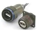


 工商网监
湘ICP备2023018690号
工商网监
湘ICP备2023018690号
