X3DC07E2S
Rev F
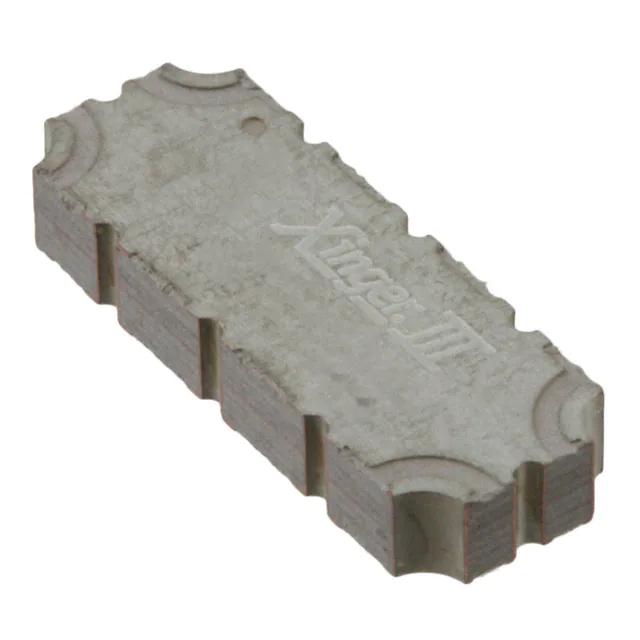
Doherty Combiner
Description:
The X3DC07E2S is a low profile, high performance Doherty
Combiner in a new easy to use, manufacturing friendly surface mount
package. The X3DC07E2S is designed particularly for Doherty
Amplifier applications, where tightly controlled phase and amplitude
imbalance as well as low insertion loss are required for maximum and
low power condition. It can be used in high power applications up to
200 watts.
Parts have been subjected to rigorous qualification testing and they
are manufactured using materials with coefficients of thermal
expansion (CTE) compatible with common substrates such as FR4,
G-10, RF-35, RO4350 and polyimide. Produced with 6 of 6 RoHS
compliant tin immersion finish.
Features:
• 728 - 768 MHz
• High Power
• Low Amp
Imbalance
• Very Low Loss
• Production
Friendly
• Tape and Reel
• Lead Free
Electrical Specifications**
Frequency
Return Loss
Insertion
Loss [1]
Amplitude
Imbalance [1]
[1]
Phase
Imbalance [1]
MHz
dB Min
dB Max
dB Max
Degrees
728 – 768
20
0.15
±0.12
90 ± 3.0
Return Loss
Insertion
Loss [2]
Port
Extension[3]
Power[4]
Operating
Temp.
dB Min
dB Max
Degrees
Avg. CW
Watts@95°C
ºC
20
0.25
0
200
-55 to +150
[2]
**Specification based on performance of unit properly installed on a TTM test board
[1] At maximum power condition, Doherty combiner functions as an equal-split power combiner.
[2] At low power condition, Doherty combiner functions as a 100Ω to 50Ω impedance transformer.
[3] There are short 50 ohm lines associated with input ports of 0° at 748MHz. Details in page 2.
[4] Average power handling which represents low power mode
Mechanical Outline:
1
�X3DC07E2S
Rev F
Insertion Loss and Power Derating Curves
Insertion Loss Derating
Power Derating
The insertion loss, at a given frequency, of a group of
doherty combiners is measured at 25°C and then
averaged. The measurements are performed under
small signal conditions (i.e. using a Vector Network
Analyzer). The process is repeated at 95°C and 150°C.
A best-fit line for the measured data is computed and then
plotted from -55°C to 150°C.
The power handling and corresponding power
derating plots are a function of the thermal resistance,
mounting
surface
temperature
(base
plate
temperature), maximum continuous operating
temperature of the Doherty combiner, and the thermal
insertion loss. The thermal insertion loss is defined in
the Power Handling section of the data sheet.
As the mounting interface temperature approaches
the maximum continuous operating temperature, the
power handling decreases to zero.
If mounting temperature is greater than 95°C, Xinger
doherty combiner will perform reliably as long as the
input power is derated to the curve above.
2
�X3DC07E2S
Rev F
Typical Performance (-55°C, 25°C, 95°C)
Return Loss for X3DC07E2S (Maximum Power Condition)
0
-55ºC
25ºC
95ºC
Return Loss (dB)
-10
-20
-30
-20
-30
-40
-40
-50
Return Loss for X3DC07E2S (Low Power Condition)
0
-55ºC
25ºC
95ºC
-10
Return Loss (dB)
728-768 MHz
730
735
740
755
750
745
Frequency (MHz)
760
-50
765
Insertion Loss for X3DC07E2S (Maximum Power Condition)
0
735
740
750
755
745
Frequency (MHz)
760
765
Insertion Loss for X3DC07E2S (Low Power Condition)
0
-55ºC
25ºC
95ºC
-0.02
730
-55ºC
25ºC
95ºC
-0.05
Insertion Loss (dB)
Insertion Loss (dB)
-0.04
-0.06
-0.08
-0.1
-0.12
-0.1
-0.15
-0.2
-0.25
-0.14
730
735
740
745
750
755
Frequency (MHz)
760
765
-0.3
730
735
740
745
750
755
Frequency (MHz)
760
765
3
�X3DC07E2S
Rev F
Phase Balance for X3DC07E2S
-55ºC
25ºC
95ºC
-86
-55ºC
25ºC
95ºC
0.15
0.1
Amplitude Balance (deg)
-88
Phase Balance (deg)
Amplitude Balance for X3DC07E2S
0.2
-90
-92
0.05
0
-0.05
-0.1
-0.15
-94
730
735
740
745
750
755
Frequency (MHz)
760
765
-0.2
730
735
740
755
750
745
Frequency (MHz)
760
765
4
�X3DC07E2S
Rev F
Definition of the Specifications
To guarantee the part performance in Doherty architecture, the part is specified in Doherty operation for
maximum power condition and low power condition. The following specification definition assumes the extra
port extension is already applied to the raw S parameter and the parts is measured with Pin n connected to
Port n (where n=1, 2, 3, 4).
•
Maximum power condition
Under the maximum power condition, the symmetrical Doherty architecture requires main amplifier and peak
amplifier to work at full capacity with the optimum termination (50 Ω). The two amplifiers should deliver RF
power of equal magnitude and 90 degree phase difference. Doherty combiner functions as a coherent power
combiner and supplies the 90 degree phase compensation. The following specification is defined with 50 Ω
port impedance at three ports for this condition. The return loss and the insertion loss in max power mode
are not affected by the 50 ohm lossless port rotation mentioned in electrical spec table in page 1. The phase
imbalance and the amplitude imbalance are not affected either since port rotation are taken off equally from
the main and the peak amp port.
Parameter
Definition
Mathematical Representation
Return Loss
The impedance match at the
combining port to a 50Ω system.
Insertion Loss
The combined power divided by
the sum of input power under the
perfect combining condition.
Phase Imbalance
The phase difference between
Peak-Combined path and MainCombined path at ωc = 748MHz
Amplitude Imbalance
•
The magnitude difference
between Peak-Combined path
and Main-Combined path.
Low power condition
20 log|S11 |
2 |
2 |)
+ |𝑆𝑆14
10log(|𝑆𝑆13
Phase (S14 (ωc )) − Phase(S13 (ωc ))
20 log|S14 | + 20 log|S13 |
2
Under low power condition, the Doherty operation turns off peak amplifier and requires main amplifier to be
terminated with double of the optimum impedance (100 Ω). In this configuration, Doherty combiner servers
as an impedance transformer transforming 50 Ω at combining port to 100 Ω at main amplifier port. The
following specification is defined under the port impedance condition of Port 1 (Combining Port) 50 Ω, Port 4
(Main Amp Port) 100 Ω and Port 3 (Peak Amp Port) open. With the peak amp left off, the extra line length in
that port (see figure in page 2) acts as an open stub which shifts the low power mode return loss null and
insertion loss. The offset line length needs to be adjusted taking the port rotation number into consideration
so that the junction of 50 Ω and 35 Ω transmission line sees high impedance instead of the part edge. The
return loss and the insertion loss defined below are after the offset line adjustments specified in the spec
table.
Parameter
Definition
Return Loss
The impedance match
of the 50 to100 Ω
transformer.
Insertion Loss
The output power
divided by input power.
Mathematical Representation
20 log|S11 |
20 log|S41 |
5
�X3DC07E2S
Rev F
Packaging and Ordering Information:
Parts are available in reels. Packaging follows EIA 481-2. Parts are oriented in tape and reel as shown below.
Minimum order quantities are 2000 per reel.
.079
[2.00]
.012
[0.30]
Ø.059
[Ø1.50]
.157
[4.00]
.069
[1.75]
.453
[11.50]
.591
[15.00]
Ø.059
[Ø1.50]
.228
[5.80]
.315
[8.00]
XX XX
.094
[2.40]
.945
[24.00]
Contact us:
rf&s_support@ttm.com
6
�
很抱歉,暂时无法提供与“X3DC07E2S”相匹配的价格&库存,您可以联系我们找货
免费人工找货